EP0172367A2 - Membranverbundpumpe - Google Patents
Membranverbundpumpe Download PDFInfo
- Publication number
- EP0172367A2 EP0172367A2 EP85108051A EP85108051A EP0172367A2 EP 0172367 A2 EP0172367 A2 EP 0172367A2 EP 85108051 A EP85108051 A EP 85108051A EP 85108051 A EP85108051 A EP 85108051A EP 0172367 A2 EP0172367 A2 EP 0172367A2
- Authority
- EP
- European Patent Office
- Prior art keywords
- valve
- piston
- pressure chamber
- pump
- gas
- Prior art date
- Legal status (The legal status is an assumption and is not a legal conclusion. Google has not performed a legal analysis and makes no representation as to the accuracy of the status listed.)
- Granted
Links
Images

Classifications
-
- F—MECHANICAL ENGINEERING; LIGHTING; HEATING; WEAPONS; BLASTING
- F04—POSITIVE - DISPLACEMENT MACHINES FOR LIQUIDS; PUMPS FOR LIQUIDS OR ELASTIC FLUIDS
- F04B—POSITIVE-DISPLACEMENT MACHINES FOR LIQUIDS; PUMPS
- F04B43/00—Machines, pumps, or pumping installations having flexible working members
- F04B43/02—Machines, pumps, or pumping installations having flexible working members having plate-like flexible members, e.g. diaphragms
- F04B43/06—Pumps having fluid drive
- F04B43/073—Pumps having fluid drive the actuating fluid being controlled by at least one valve
- F04B43/0736—Pumps having fluid drive the actuating fluid being controlled by at least one valve with two or more pumping chambers in parallel
-
- F—MECHANICAL ENGINEERING; LIGHTING; HEATING; WEAPONS; BLASTING
- F01—MACHINES OR ENGINES IN GENERAL; ENGINE PLANTS IN GENERAL; STEAM ENGINES
- F01L—CYCLICALLY OPERATING VALVES FOR MACHINES OR ENGINES
- F01L25/00—Drive, or adjustment during the operation, or distribution or expansion valves by non-mechanical means
- F01L25/02—Drive, or adjustment during the operation, or distribution or expansion valves by non-mechanical means by fluid means
- F01L25/04—Drive, or adjustment during the operation, or distribution or expansion valves by non-mechanical means by fluid means by working-fluid of machine or engine, e.g. free-piston machine
- F01L25/06—Arrangements with main and auxiliary valves, at least one of them being fluid-driven
- F01L25/063—Arrangements with main and auxiliary valves, at least one of them being fluid-driven the auxiliary valve being actuated by the working motor-piston or piston-rod
-
- Y—GENERAL TAGGING OF NEW TECHNOLOGICAL DEVELOPMENTS; GENERAL TAGGING OF CROSS-SECTIONAL TECHNOLOGIES SPANNING OVER SEVERAL SECTIONS OF THE IPC; TECHNICAL SUBJECTS COVERED BY FORMER USPC CROSS-REFERENCE ART COLLECTIONS [XRACs] AND DIGESTS
- Y10—TECHNICAL SUBJECTS COVERED BY FORMER USPC
- Y10T—TECHNICAL SUBJECTS COVERED BY FORMER US CLASSIFICATION
- Y10T137/00—Fluid handling
- Y10T137/8593—Systems
- Y10T137/86493—Multi-way valve unit
- Y10T137/86574—Supply and exhaust
- Y10T137/86582—Pilot-actuated
- Y10T137/86606—Common to plural valve motor chambers
-
- Y—GENERAL TAGGING OF NEW TECHNOLOGICAL DEVELOPMENTS; GENERAL TAGGING OF CROSS-SECTIONAL TECHNOLOGIES SPANNING OVER SEVERAL SECTIONS OF THE IPC; TECHNICAL SUBJECTS COVERED BY FORMER USPC CROSS-REFERENCE ART COLLECTIONS [XRACs] AND DIGESTS
- Y10—TECHNICAL SUBJECTS COVERED BY FORMER USPC
- Y10T—TECHNICAL SUBJECTS COVERED BY FORMER US CLASSIFICATION
- Y10T137/00—Fluid handling
- Y10T137/8593—Systems
- Y10T137/86493—Multi-way valve unit
- Y10T137/86574—Supply and exhaust
- Y10T137/8667—Reciprocating valve
- Y10T137/86694—Piston valve
- Y10T137/8671—With annular passage [e.g., spool]
-
- Y—GENERAL TAGGING OF NEW TECHNOLOGICAL DEVELOPMENTS; GENERAL TAGGING OF CROSS-SECTIONAL TECHNOLOGIES SPANNING OVER SEVERAL SECTIONS OF THE IPC; TECHNICAL SUBJECTS COVERED BY FORMER USPC CROSS-REFERENCE ART COLLECTIONS [XRACs] AND DIGESTS
- Y10—TECHNICAL SUBJECTS COVERED BY FORMER USPC
- Y10T—TECHNICAL SUBJECTS COVERED BY FORMER US CLASSIFICATION
- Y10T137/00—Fluid handling
- Y10T137/8593—Systems
- Y10T137/86493—Multi-way valve unit
- Y10T137/86718—Dividing into parallel flow paths with recombining
- Y10T137/86759—Reciprocating
- Y10T137/86791—Piston
-
- Y—GENERAL TAGGING OF NEW TECHNOLOGICAL DEVELOPMENTS; GENERAL TAGGING OF CROSS-SECTIONAL TECHNOLOGIES SPANNING OVER SEVERAL SECTIONS OF THE IPC; TECHNICAL SUBJECTS COVERED BY FORMER USPC CROSS-REFERENCE ART COLLECTIONS [XRACs] AND DIGESTS
- Y10—TECHNICAL SUBJECTS COVERED BY FORMER USPC
- Y10T—TECHNICAL SUBJECTS COVERED BY FORMER US CLASSIFICATION
- Y10T137/00—Fluid handling
- Y10T137/8593—Systems
- Y10T137/87169—Supply and exhaust
- Y10T137/87177—With bypass
Definitions
- This invention relates to pneumatically operated diaphragm pumps and, more p articularlv, to a method and apparatus for avoiding icing and/or stalling.
- Pneumatically driven pumps are well known for their utility and frequently utilize either double acting pistons or diaphragms to alternately compress and expand pump chambers to force the exit of the fluid from one chamber while inducing the entry of additional fluid into the other chamber. Since pneumatically driven pumps do not require an electric or internal combustion engine to drive the oumoinq chambers, such pumps are particularly useful in locations where combustible or explosive materials are present.
- Fnown prior art pumps have attacked the problem of ice for- maticn by incorporating an air dryer to remove moisture from the air supply system.
- air dryers are often extremely expensive and only marginally successful in climatic conditions of low temperature and high humidity. The additional drop in operational pressure through the air drver may also be undesirable.
- Still another known approach to this icing problem is the use of chemical deicing agents such as ethyl alcohol and ethylene glycol.
- chemical deicing agents such as ethyl alcohol and ethylene glycol.
- these chemical deicing agents are often marginally successful and also introduce an undesirable environmental condition in introducing ethyl alcohol and ethylene glycol vapors into the ambient air.
- icing is reduced by :he controlled bleeding of hiqh pressure air from an internal nigh pressure chamber to an internal low pressure chamber.
- the nigh pressure air furnishes internal energy and thus velocity to the exraust air and thus mechanicallv disolaces ice as it forms.
- this air by-pass provides a stepdown release of the motive gas, i.e., it reduces the pressure drop across the valve by increasing the pressure in the low pressure chamber and increases the pressure drop across the outlet aperture to increase exit velocity as indicated above.
- Pneumatically operable oumos typically use a source of compressed air which is distributed hy a reciprocatinq three-way valve to drive the pistons or diaphragm in the pumping chambers.
- Known valves such as described as prior art in the Wilden Patent No. 3,071,118 generally require lubrication with an oil mist because the metal piston travels in a metal cylinder. The clearance required between such metal narts prevents a tight seal, allowing a high amount of air leakaqe, makinq it inefficient.
- the use of an oil mist is undesirable in many applications because of the contamination of the atmosphere and material such as foodstuffs being pumped.
- Another known type of control valve such as disclosed in the aforementioned patent to Budde uses a metallic piston with a resilient plastic compression seal which eliminates the need for lubrication. While such resilient piston seal rinqs or o-rinqs create a barrier that prevents leakage of the compressed air between the piston and the piston wall, the use thereof in many cases is not cost effective due to the frequency of replacement of the seal rings. Generally, the rings fail because the actual contact surface is extremely small compared to the diameter and weight of the piston, uniformly for vertical piston rings but uneven on the lower part of the ring for horizontal pistons as a result of the force of gravity.
- the present invention eliminates the maintenance problems of oil mist free valves by forming the piston seals integrally with the piston of a suitable plastic material such as polytetrafluorethylene (PTFE) or the like. In this way, the contact surface area may be increased relative to the diameter and weight of the piston.
- a suitable plastic material such as polytetrafluorethylene (PTFE) or the like.
- Another problem associated with double diaphraqm pumos is the potential for stalling. Stalling is prevented in the present 'invention by the use of a pilot valve cylinder resiliently deformable under pressure so that air can be bled from a selected one of the potentially opposing chambers of the air distribution valve to thereby ensure operation.
- the bleeding of air from a selected valve chamber may be used to slow the speed of reciprocating movement of the air distribution valve piston during the terminal part of a movement thereof. This reduces the impact of the piston on the end walls of the cylinder and thus reduces the potential deformation and sticking of the piston to the end wall.
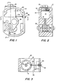
- the housing 10 has an air inlet orifice or aperture in which a plug 12 may be threadably inserted.
- the inlet passageway for the pump housing leads to the high pressure chamber 14 defined by an internal partition 16 more easily seen in Figure 3.
- the high pressure chamber 14 communicates via a passageway 18 to the horizontal bore 20 of Figure 1 in which the valve assembly 22 is mounted as shown in Figure 2.
- a passageway 32 is provided from the low pressure chamber 29 to the high pressure chamber 14.
- a needle valve 36 in a valve seat 34 may be manually adjustable externally of the housing by rotating the end 38 of the needle valve 36 in the threads 40 to regulate the amount of air bled from the high pressure chamber 14 to the low pressure chamber 29.
- the pump housing 10 may be mounted between left and right lateral chambers divided respectively by a flexible diaphragm 50 into a driving chamber 28 and the pumping chamber 52, and by diaphragm 46 into a chamber 26 and a pumping chamber 48. Entrance of the material being pumped into the pumping chambers 48 and 52 respectivelv may be provided by suitable conventional one-way valves 54 and 56. Similarly, egress from the pumping chambers 48 and 52 may be respectively provided by any suitable conventional one-way valves 58 and 60.
- the diaphragms 46 and 50 may be connected in a suitable conventional manner by the piston 44 slidably mounted within the central bore 42 of the housing shown in Figure 1.
- the pilot piston 64 of the valve assembly 62 is mechanically forced to the right bv the movement of the diaphragm 50.
- the movement of the piston 64 to the right effects the operation of the air distribution valve to cause air to be applied from the high pressure chamber 14 of Figure 5 to fill the chamber 28 and to vent the chamber 26.
- the piston 64 of the pilot valve remains in this extreme right position as the diaphragm piston 44 completes its movement to the left, at which time the diaphragm 46 mechanically moves the piston 64 to the left as shown in Figure 6.
- Movement of the piston 64 of the pilot valve to the left as shown in Figure 6 effects movement of the piston 72 of the air distribution valve 62 to the right to effect a further cycle of the pump as will be subsequently explained.
- Typical operating air pressure is about 70 to 100 psi from the compressor and is desirably about 80-85 psi within the high pressure chamber 14.
- the high pressure chamber 14 serves to reduce turbulence and may house a filter.
- the pressure of the motive gas in the low pressure chamber 29 is generally about 20 psi.
- the adjustment of the needle valve 36 is largely a function of temperature and the quality of the motive gas, and qenerallv comprises less than about eighteen percent of the volume of the low pressure chamber 29.
- the preferred embodiment of the air distribution valve 62 comprises a cylinder 70 and is fitted with end caps 71 and 73.
- the air distribution valve piston 72 is slidably mounted for reciprocating movement within the cvlinder 70 between the end caps 71 and 73, with the projections 75 and 77 providing a seal.
- the movement of the piston 72 within the valve cylinder 70 is essentially frictionless and the use of seals avoided.
- the movement of the pilot piston 64 within the sleeve 74 is essentially frictionless and the use of seals likewise avoided.
- the valve piston 72 internally receives a cvlindrical sleeve 74 which together with the end caps 71 and 73 and the cylinder 70 define the housinq within which the piston 72 reciprocates.
- the sleeve 74 receives the pilot valve piston 64.
- the cylinder 70 and the pilot piston 64 may be made of a suitable ferrous alloy.
- the piston 72 and end caps 71 and 73 are desirably made of a relatively light weight plastic material such as polytetrafluorethylene (PTFE) or other low friction coefficient material.
- PTFE polytetrafluorethylene
- the sleeve 74 may also be manufactured of a low friction coefficient material.
- end caps 71 and 73 serve to maintain the sleeve 74 longitudinally immobile as the pilot piston 64 reciprocates therein.
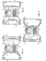
- the apertures 86 in the cylinder 70 provide an exit route for the air from the driving chamber 28 of Figure 4 into the annular cavity 88 of Figure 9(A) to the low pressure chamber 29 of Figures 1 and 3, and thence through the passageway 85 of Figure 1 to the atmosphere.
- the piston 72 is maintained in the left hand position by the high pressure air within the cavity 82 applying pressure as shown by the arrows 90.
- the force represented by the arrows 90 is opposed by the pressure differential between the cavities 82 and 88 as illustrated by the arrows 92.
- the pressure represented by the arrows 90 is controlling because of the difference in surface area.
- the high pressure air enters through the aperture 80 into the cavity 82 and exits through the apertures 86 to the chamber 28.
- the pressure of the air within the cavity 82 acts on the projection 77, as shown by the arrows 96, to maintain the piston 72 in the right hand position against the force exerted by the arrows 98 on the projection 75 in response to the pressure differential between the cavities 82 and 100.
- the air from the chamber 26 passes through the aperture 84 in the cylinder 70 into the low pressure chamber 29 and thence to the atmosphere.
- the sleeve 74 is made of a material deformable under a pressure of about sixty percent of the operating pressure of the pump, e.g., about 55 to 60 psi. This pressure deformation serves to effect leakage between the piston 72 and the sleeve 74 when the sleeve 74 is not supported by the pilot piston 64, e.g., as shown by the arrow 102 in Figure 9(B). This leak is effective to prevent stalling by reducing the likelihood of equal and opposite pressures in adjacent cavities within the valve. In addition, the leak decreases the pressure differential tending to move the piston 72 and thus slows the reciprocating movement of the piston slightly, reducing impact with the end caps and the possibility of deformation and/or sticking of the plastic surfaces.
Landscapes
- Engineering & Computer Science (AREA)
- Mechanical Engineering (AREA)
- General Engineering & Computer Science (AREA)
- Reciprocating Pumps (AREA)
- Details Of Reciprocating Pumps (AREA)
Priority Applications (1)
| Application Number | Priority Date | Filing Date | Title |
|---|---|---|---|
| AT85108051T ATE56253T1 (de) | 1984-07-02 | 1985-06-28 | Membranverbundpumpe. |
Applications Claiming Priority (2)
| Application Number | Priority Date | Filing Date | Title |
|---|---|---|---|
| US06/626,915 US4566867A (en) | 1984-07-02 | 1984-07-02 | Dual diaphragm pump |
| US626915 | 1984-07-02 |
Publications (4)
| Publication Number | Publication Date |
|---|---|
| EP0172367A2 true EP0172367A2 (de) | 1986-02-26 |
| EP0172367A3 EP0172367A3 (en) | 1987-01-21 |
| EP0172367B1 EP0172367B1 (de) | 1990-09-05 |
| EP0172367B2 EP0172367B2 (de) | 1993-03-24 |
Family
ID=24512402
Family Applications (1)
| Application Number | Title | Priority Date | Filing Date |
|---|---|---|---|
| EP85108051A Expired - Lifetime EP0172367B2 (de) | 1984-07-02 | 1985-06-28 | Membranverbundpumpe |
Country Status (8)
| Country | Link |
|---|---|
| US (2) | US4566867A (de) |
| EP (1) | EP0172367B2 (de) |
| JP (1) | JP2604133B2 (de) |
| AT (1) | ATE56253T1 (de) |
| AU (1) | AU584905B2 (de) |
| CA (1) | CA1234720A (de) |
| DE (1) | DE3579537D1 (de) |
| MX (1) | MX162811A (de) |
Cited By (3)
| Publication number | Priority date | Publication date | Assignee | Title |
|---|---|---|---|---|
| DE3706351A1 (de) * | 1987-02-27 | 1988-09-08 | Kopperschmidt Mueller & Co | Durch einen druckluft-kolbenmotor angetriebene fluessigkeits-kolbenpumpe |
| WO1995017596A1 (en) * | 1993-12-22 | 1995-06-29 | Shurflo Limited | A pump |
| GB2288442A (en) * | 1994-04-13 | 1995-10-18 | Graco Inc | Valve for controlling a reciprocating air operated pump and with a bleed feature to inhibit icing |
Families Citing this family (24)
| Publication number | Priority date | Publication date | Assignee | Title |
|---|---|---|---|---|
| US4566867A (en) * | 1984-07-02 | 1986-01-28 | Alberto Bazan | Dual diaphragm pump |
| JPH02245401A (ja) * | 1989-03-17 | 1990-10-01 | Nippon Gurei Kk | エアモータの凍結防止装置 |
| US5326234A (en) * | 1993-02-17 | 1994-07-05 | Versa-Matic Tool, Inc. | Fluid driven pump |
| US5480292A (en) * | 1993-05-19 | 1996-01-02 | Asti Sae | Dual chamber pump |
| US5368452A (en) * | 1993-07-20 | 1994-11-29 | Graco Inc. | Double diaphragm pump having two-stage air valve actuator |
| EP0754271A4 (de) * | 1994-03-03 | 1998-12-16 | John M Simmons | Pumpe mit pneumatisch geregelten hin- und herbewegung |
| US5893707A (en) * | 1994-03-03 | 1999-04-13 | Simmons; John M. | Pneumatically shifted reciprocating pump |
| US5567477A (en) * | 1995-09-22 | 1996-10-22 | Snyder, Jr.; Guy T. | Method and apparatus for pumping high viscosity fluids |
| US5620746A (en) * | 1995-09-22 | 1997-04-15 | Snyder, Jr.; Guy T. | Method and apparatus for reversibly pumping high viscosity fluids |
| US6158967A (en) * | 1998-08-26 | 2000-12-12 | Texas Pressure Systems, Inc. | Barrier fluid seal, reciprocating pump and operating method |
| ES2159248B1 (es) * | 1999-08-09 | 2002-04-01 | Pinturas Jaque S L | Bomba volumetrica de doble membrana aplicable a maquina pintabandas y a otros usos. |
| JP3515070B2 (ja) | 2000-12-18 | 2004-04-05 | 株式会社ヤマダコーポレーション | ポンプの再始動装置 |
| US6685443B2 (en) | 2001-07-11 | 2004-02-03 | John M. Simmons | Pneumatic reciprocating pump |
| US6644941B1 (en) * | 2002-04-18 | 2003-11-11 | Ingersoll-Rand Company | Apparatus and method for reducing ice formation in gas-driven motors |
| US6962487B2 (en) * | 2003-08-07 | 2005-11-08 | Versa-Matic Tool, Inc. | Fluid driven pump with improved exhaust port arrangement |
| US7527086B2 (en) * | 2004-07-20 | 2009-05-05 | National Taiwan University | Double-acting device for generating synthetic jets |
| US20070092385A1 (en) * | 2005-10-20 | 2007-04-26 | Petrie Pe Greg A | Pump and valve actuator system and method |
| US7458309B2 (en) * | 2006-05-18 | 2008-12-02 | Simmons Tom M | Reciprocating pump, system or reciprocating pumps, and method of driving reciprocating pumps |
| US20090010768A1 (en) * | 2007-07-03 | 2009-01-08 | Versa-Matic Pump, Inc. | Pumping apparatus for shear-sensitive fluids |
| US20110033316A1 (en) * | 2009-08-05 | 2011-02-10 | Tim Marchbanks | System for controlling the stroke of an air-operated double diaphragm pump |
| CN102227549A (zh) * | 2010-02-24 | 2011-10-26 | 丰田自动车株式会社 | 内燃机的控制装置 |
| US9360000B2 (en) | 2012-03-15 | 2016-06-07 | Graco Fluid Handling (A) Inc. | Reciprocating pumps and related methods |
| US9004881B2 (en) * | 2012-04-20 | 2015-04-14 | Simmons Development, Llc | Modular fluid-driven diaphragm pump and related methods |
| CN115556907A (zh) * | 2022-09-26 | 2023-01-03 | 山东北溟科技有限公司 | 浮力调节装置 |
Family Cites Families (6)
| Publication number | Priority date | Publication date | Assignee | Title |
|---|---|---|---|---|
| US2944528A (en) * | 1959-07-24 | 1960-07-12 | Mcneil Machine & Eng Co | Air distributing valves |
| US3791768A (en) * | 1972-06-16 | 1974-02-12 | W Wanner | Fluid pump |
| DE3112434A1 (de) * | 1981-03-28 | 1982-10-07 | Depa GmbH, 4000 Düsseldorf | Druckluftgetriebene doppelmembran-pumpe |
| DE3150976A1 (de) * | 1981-12-23 | 1983-06-30 | DEPA Gesellschaft für Verfahrenstechnik mbH, 4000 Düsseldorf | Druckluftgetriebene doppelmembranpumpe |
| AU553956B2 (en) * | 1981-12-23 | 1986-07-31 | Devilbiss Company, The | Twin coupled-diaphragm pump |
| US4566867A (en) * | 1984-07-02 | 1986-01-28 | Alberto Bazan | Dual diaphragm pump |
-
1984
- 1984-07-02 US US06/626,915 patent/US4566867A/en not_active Expired - Lifetime
-
1985
- 1985-06-26 CA CA000485312A patent/CA1234720A/en not_active Expired
- 1985-06-28 DE DE8585108051T patent/DE3579537D1/de not_active Expired - Lifetime
- 1985-06-28 EP EP85108051A patent/EP0172367B2/de not_active Expired - Lifetime
- 1985-06-28 AT AT85108051T patent/ATE56253T1/de not_active IP Right Cessation
- 1985-07-01 MX MX205846A patent/MX162811A/es unknown
- 1985-07-02 AU AU44500/85A patent/AU584905B2/en not_active Ceased
- 1985-07-02 JP JP60144110A patent/JP2604133B2/ja not_active Expired - Lifetime
- 1985-08-29 US US06/770,420 patent/US4708601A/en not_active Expired - Lifetime
Cited By (4)
| Publication number | Priority date | Publication date | Assignee | Title |
|---|---|---|---|---|
| DE3706351A1 (de) * | 1987-02-27 | 1988-09-08 | Kopperschmidt Mueller & Co | Durch einen druckluft-kolbenmotor angetriebene fluessigkeits-kolbenpumpe |
| WO1995017596A1 (en) * | 1993-12-22 | 1995-06-29 | Shurflo Limited | A pump |
| US5772412A (en) * | 1993-12-22 | 1998-06-30 | Shurflo Limited | Pump incorporating pressure-regulated venting means |
| GB2288442A (en) * | 1994-04-13 | 1995-10-18 | Graco Inc | Valve for controlling a reciprocating air operated pump and with a bleed feature to inhibit icing |
Also Published As
| Publication number | Publication date |
|---|---|
| EP0172367A3 (en) | 1987-01-21 |
| MX162811A (es) | 1991-06-26 |
| DE3579537D1 (de) | 1990-10-11 |
| JP2604133B2 (ja) | 1997-04-30 |
| EP0172367B1 (de) | 1990-09-05 |
| AU584905B2 (en) | 1989-06-08 |
| CA1234720A (en) | 1988-04-05 |
| ATE56253T1 (de) | 1990-09-15 |
| EP0172367B2 (de) | 1993-03-24 |
| AU4450085A (en) | 1986-01-09 |
| US4566867A (en) | 1986-01-28 |
| US4708601A (en) | 1987-11-24 |
| JPS6119989A (ja) | 1986-01-28 |
Similar Documents
| Publication | Publication Date | Title |
|---|---|---|
| EP0172367A2 (de) | Membranverbundpumpe | |
| US5957670A (en) | Air driven diaphragm pump | |
| US3146940A (en) | Reverse leakage seal for reciprocating parts | |
| EP0280264B1 (de) | Mehrstufen-Vakuumpumpe | |
| US3620652A (en) | Compressor with rolling diaphragm seal | |
| KR950001095A (ko) | 펌프 | |
| US5366353A (en) | Air valve with bleed feature to inhibit icing | |
| CA2061903A1 (en) | Compression spring fluid motor | |
| KR920010564A (ko) | 쌍 스크류 압축기용 용량 체적률 제어장치 | |
| KR100586139B1 (ko) | 멀티디렉션 펌프 | |
| SE9500588L (sv) | Luftpump | |
| US3547005A (en) | Device with rolling diaphragm seal separating gas and liquid | |
| US4173433A (en) | Two-stage gas compressor | |
| EP0340150B1 (de) | Verdichter mit rotierender Kurbelwelle | |
| US3834837A (en) | Air compressor with governor | |
| US4472111A (en) | Apparatus for generating high pressure fluid | |
| US4976591A (en) | Self lubricating, two stage variable compressor | |
| US684806A (en) | Pressure-regulator for pumps. | |
| US4738600A (en) | Lubricating system | |
| US3229900A (en) | Reverse leakage seal for reciprocating parts | |
| US3068798A (en) | Metering pumps | |
| US2726032A (en) | Compressor, including unloading head | |
| US4384826A (en) | Method and apparatus for controlling communication with a compressor unloader chamber | |
| US4427346A (en) | Motor-driven reciprocating piston compressor, particularly for hermetically encapsulated small refrigerators | |
| US1760636A (en) | Refrigerant compressor |
Legal Events
| Date | Code | Title | Description |
|---|---|---|---|
| PUAI | Public reference made under article 153(3) epc to a published international application that has entered the european phase |
Free format text: ORIGINAL CODE: 0009012 |
|
| AK | Designated contracting states |
Designated state(s): AT BE CH DE FR GB IT LI NL SE |
|
| PUAL | Search report despatched |
Free format text: ORIGINAL CODE: 0009013 |
|
| AK | Designated contracting states |
Kind code of ref document: A3 Designated state(s): AT BE CH DE FR GB IT LI NL SE |
|
| 17P | Request for examination filed |
Effective date: 19870625 |
|
| 17Q | First examination report despatched |
Effective date: 19880630 |
|
| GRAA | (expected) grant |
Free format text: ORIGINAL CODE: 0009210 |
|
| AK | Designated contracting states |
Kind code of ref document: B1 Designated state(s): AT BE CH DE FR GB IT LI NL SE |
|
| PG25 | Lapsed in a contracting state [announced via postgrant information from national office to epo] |
Ref country code: SE Effective date: 19900905 Ref country code: NL Effective date: 19900905 |
|
| REF | Corresponds to: |
Ref document number: 56253 Country of ref document: AT Date of ref document: 19900915 Kind code of ref document: T |
|
| ET | Fr: translation filed | ||
| REF | Corresponds to: |
Ref document number: 3579537 Country of ref document: DE Date of ref document: 19901011 |
|
| NLV1 | Nl: lapsed or annulled due to failure to fulfill the requirements of art. 29p and 29m of the patents act | ||
| ITF | It: translation for a ep patent filed | ||
| NLXE | Nl: other communications concerning ep-patents (part 3 heading xe) |
Free format text: REQUEST FOR RESTORATION TO THE PRIOR STATE HAS BEEN FILED ON 910326 |
|
| PLBI | Opposition filed |
Free format text: ORIGINAL CODE: 0009260 |
|
| PGFP | Annual fee paid to national office [announced via postgrant information from national office to epo] |
Ref country code: SE Payment date: 19910627 Year of fee payment: 7 |
|
| ITTA | It: last paid annual fee | ||
| 26 | Opposition filed |
Opponent name: KWW GESELLSCHAFT FUER VERFAHRENSTECHNIK MBH Effective date: 19910518 |
|
| NLXE | Nl: other communications concerning ep-patents (part 3 heading xe) |
Free format text: THE REQUEST FOR THE RESTORATION TO THE PRIOR STATE HAS PROVIDED OF 910326,HAS BEEN REJECTED ON 920326 |
|
| PUAH | Patent maintained in amended form |
Free format text: ORIGINAL CODE: 0009272 |
|
| STAA | Information on the status of an ep patent application or granted ep patent |
Free format text: STATUS: PATENT MAINTAINED AS AMENDED |
|
| RAP4 | Party data changed (patent owner data changed or rights of a patent transferred) |
Owner name: MURPHY, DONALD M. Owner name: BAZAN, ALBERTO |
|
| 27A | Patent maintained in amended form |
Effective date: 19930324 |
|
| AK | Designated contracting states |
Kind code of ref document: B2 Designated state(s): AT BE CH DE FR GB IT LI NL SE |
|
| REG | Reference to a national code |
Ref country code: CH Ref legal event code: AEN |
|
| ET3 | Fr: translation filed ** decision concerning opposition | ||
| ITF | It: translation for a ep patent filed | ||
| REG | Reference to a national code |
Ref country code: GB Ref legal event code: IF02 |
|
| PGFP | Annual fee paid to national office [announced via postgrant information from national office to epo] |
Ref country code: GB Payment date: 20040630 Year of fee payment: 20 |
|
| PGFP | Annual fee paid to national office [announced via postgrant information from national office to epo] |
Ref country code: FR Payment date: 20040708 Year of fee payment: 20 Ref country code: DE Payment date: 20040708 Year of fee payment: 20 |
|
| PGFP | Annual fee paid to national office [announced via postgrant information from national office to epo] |
Ref country code: AT Payment date: 20040713 Year of fee payment: 20 |
|
| PGFP | Annual fee paid to national office [announced via postgrant information from national office to epo] |
Ref country code: CH Payment date: 20040715 Year of fee payment: 20 |
|
| PGFP | Annual fee paid to national office [announced via postgrant information from national office to epo] |
Ref country code: BE Payment date: 20040813 Year of fee payment: 20 |
|
| PG25 | Lapsed in a contracting state [announced via postgrant information from national office to epo] |
Ref country code: GB Free format text: LAPSE BECAUSE OF EXPIRATION OF PROTECTION Effective date: 20050627 |
|
| BE20 | Be: patent expired |
Owner name: *MURPHY DONALD M. Effective date: 20050628 Owner name: *BAZAN ALBERTO Effective date: 20050628 |
|
| REG | Reference to a national code |
Ref country code: GB Ref legal event code: PE20 |
|
| REG | Reference to a national code |
Ref country code: CH Ref legal event code: PL |
|
| BE20 | Be: patent expired |
Owner name: *MURPHY DONALD M. Effective date: 20050628 Owner name: *BAZAN ALBERTO Effective date: 20050628 |