EP2541016A1 - Steuervorrichtung für einen verbrennungsmotor - Google Patents
Steuervorrichtung für einen verbrennungsmotor Download PDFInfo
- Publication number
- EP2541016A1 EP2541016A1 EP10776069A EP10776069A EP2541016A1 EP 2541016 A1 EP2541016 A1 EP 2541016A1 EP 10776069 A EP10776069 A EP 10776069A EP 10776069 A EP10776069 A EP 10776069A EP 2541016 A1 EP2541016 A1 EP 2541016A1
- Authority
- EP
- European Patent Office
- Prior art keywords
- pressure
- valve
- pressure chamber
- actuator
- diaphragm
- Prior art date
- Legal status (The legal status is an assumption and is not a legal conclusion. Google has not performed a legal analysis and makes no representation as to the accuracy of the status listed.)
- Withdrawn
Links
- 238000002485 combustion reaction Methods 0.000 title claims description 37
- 235000014676 Phragmites communis Nutrition 0.000 claims abstract description 58
- 230000001105 regulatory effect Effects 0.000 claims abstract description 40
- 238000004891 communication Methods 0.000 claims abstract description 20
- 230000007246 mechanism Effects 0.000 claims description 23
- 230000001133 acceleration Effects 0.000 claims description 11
- 230000002401 inhibitory effect Effects 0.000 claims description 9
- 239000002699 waste material Substances 0.000 claims description 9
- 230000003213 activating effect Effects 0.000 claims description 6
- 238000010586 diagram Methods 0.000 description 7
- 239000000446 fuel Substances 0.000 description 7
- 230000005764 inhibitory process Effects 0.000 description 6
- 238000002347 injection Methods 0.000 description 5
- 239000007924 injection Substances 0.000 description 5
- 230000000717 retained effect Effects 0.000 description 5
- 230000007423 decrease Effects 0.000 description 4
- 230000000694 effects Effects 0.000 description 4
- 230000002829 reductive effect Effects 0.000 description 4
- 238000001816 cooling Methods 0.000 description 3
- 230000003247 decreasing effect Effects 0.000 description 3
- 238000005516 engineering process Methods 0.000 description 3
- 238000001514 detection method Methods 0.000 description 2
- 239000000428 dust Substances 0.000 description 2
- 239000011347 resin Substances 0.000 description 2
- 229920005989 resin Polymers 0.000 description 2
- 238000011144 upstream manufacturing Methods 0.000 description 2
- 230000002159 abnormal effect Effects 0.000 description 1
- 230000009471 action Effects 0.000 description 1
- 230000008859 change Effects 0.000 description 1
- 239000000498 cooling water Substances 0.000 description 1
- 238000006073 displacement reaction Methods 0.000 description 1
- 238000002474 experimental method Methods 0.000 description 1
- 239000000463 material Substances 0.000 description 1
- 239000002184 metal Substances 0.000 description 1
- 239000007769 metal material Substances 0.000 description 1
- 230000009467 reduction Effects 0.000 description 1
- 230000004043 responsiveness Effects 0.000 description 1
- 230000001360 synchronised effect Effects 0.000 description 1
- XLYOFNOQVPJJNP-UHFFFAOYSA-N water Substances O XLYOFNOQVPJJNP-UHFFFAOYSA-N 0.000 description 1
Images




Classifications
-
- F—MECHANICAL ENGINEERING; LIGHTING; HEATING; WEAPONS; BLASTING
- F02—COMBUSTION ENGINES; HOT-GAS OR COMBUSTION-PRODUCT ENGINE PLANTS
- F02B—INTERNAL-COMBUSTION PISTON ENGINES; COMBUSTION ENGINES IN GENERAL
- F02B37/00—Engines characterised by provision of pumps driven at least for part of the time by exhaust
- F02B37/12—Control of the pumps
- F02B37/18—Control of the pumps by bypassing exhaust from the inlet to the outlet of turbine or to the atmosphere
- F02B37/183—Arrangements of bypass valves or actuators therefor
- F02B37/186—Arrangements of actuators or linkage for bypass valves
-
- Y—GENERAL TAGGING OF NEW TECHNOLOGICAL DEVELOPMENTS; GENERAL TAGGING OF CROSS-SECTIONAL TECHNOLOGIES SPANNING OVER SEVERAL SECTIONS OF THE IPC; TECHNICAL SUBJECTS COVERED BY FORMER USPC CROSS-REFERENCE ART COLLECTIONS [XRACs] AND DIGESTS
- Y02—TECHNOLOGIES OR APPLICATIONS FOR MITIGATION OR ADAPTATION AGAINST CLIMATE CHANGE
- Y02T—CLIMATE CHANGE MITIGATION TECHNOLOGIES RELATED TO TRANSPORTATION
- Y02T10/00—Road transport of goods or passengers
- Y02T10/10—Internal combustion engine [ICE] based vehicles
- Y02T10/12—Improving ICE efficiencies
Definitions
- the present invention relates to an internal combustion engine control apparatus, and particularly to an internal combustion engine control apparatus equipped with a diaphragm-type actuator.
- the conventional technology for internal combustion engine control apparatuses includes an internal combustion engine control apparatus that has a variable capacity mechanism provided on a turbine side of a variable capacity turbocharger, and a diaphragm-type actuator that drives the variable capacity mechanism, for example, as disclosed in Patent Literature 1 (Japanese Patent Laid-Open No. 11-36877 ).
- the known conventional technology also includes an internal combustion engine control apparatus that is equipped with a waste gate valve that adjusts a boost pressure of an internal combustion engine, and an actuator that drives the waste gate valve, as disclosed in Patent Literature 2 (Japanese Patent Laid-Open No. 2006-274833 ).
- the above-described conventional technology employs a configuration that uses a diaphragm-type actuator.
- heat generated in an internal combustion engine is liable to be transmitted to a pressure chamber of the actuator, for example, in a case where high-load operations continue for a long time, there is the risk that the gas inside the pressure chamber will be thermally expanded and the internal pressure will rise and cause damage to the diaphragm.
- the actuator that drives the waste gate valve is arranged in the vicinity of an exhaust system (turbine and the like) which becomes a high temperature, the above-described problem is liable to occur.
- the present invention has been made to solve the above-described problem, and an object of the present invention is to provide an internal combustion engine control apparatus that is capable of preventing damage to a diaphragm caused by a high temperature and improving the heat resistance property of the actuator.
- a first aspect of the present invention is an internal combustion engine control apparatus, comprising:
- the actuator comprises a high pressure chamber and a low pressure chamber that are defined as the pressure chamber on one side and another side of the diaphragm, respectively; and the pressure release means is configured to release pressure from either one of the high pressure chamber and the low pressure chamber to the other of the high pressure chamber and the low pressure chamber.
- the internal combustion engine control apparatus comprising:
- the pressure release valve comprises a reed valve that is provided at a position that covers the communication portion from the low pressure chamber side, and that opens when a differential pressure in a forward direction that presses the diaphragm from the high pressure chamber side becomes equal to or greater than a predetermined valve opening pressure; when activating the actuator, the actuator control means maintains a pressure value of the differential pressure in a forward direction at a value that is less than the valve opening pressure while generating the differential pressure; and the pressure release means is configured to increase the differential pressure in a forward direction to a pressure that is greater than or equal to the valve opening pressure.
- the pressure release valve comprises a reed valve that is provided at a position that covers the communication portion from the high pressure chamber side, and that opens when a differential pressure in a backward direction that presses the diaphragm from the low pressure chamber side is generated; when activating the actuator, the actuator control means causes a differential pressure in a forward direction to be generated that presses the diaphragm from the high pressure chamber side; and the pressure release means is configured to generate the differential pressure in a backward direction.
- the differential pressure generating means comprises:
- the internal combustion engine control apparatus further comprising drive time release inhibiting means that inhibits operation of the pressure release means when a vehicle is moving.
- the internal combustion engine control apparatus further comprising acceleration time release inhibiting means that inhibits operation of the pressure release means at a time of acceleration of the internal combustion engine.
- the temperature acquiring means is configured to estimate a temperature of the actuator based on operating information of the internal combustion engine.
- the internal combustion engine control apparatus further comprising:
- pressure when the actuator enters an excessively high temperature state, pressure can be released from the pressure chamber by pressure release means. It is therefore possible to prevent a gas inside the pressure chamber from thermally expanding and causing damage to the diaphragm, and also to improve the heat resistance property of the actuator.
- the actuator when the actuator has entered an excessively high temperature state, pressure can be released between the high pressure chamber and the low pressure chamber by the pressure release means.
- a mechanism for pressure release can be housed inside a housing that is shut off from the outside. Consequently, since it is not necessary to provide a vent hole or the like that opens to outside as in the case of a structure in which, for example, pressure is allowed to escape to outside of the housing, foreign matter such as dust and moisture can be reliably prevented from entering into the housing from outside. Accordingly, even when a mechanism for pressure release is mounted thereto, an actuator with high reliability can be realized.
- the pressure release means when the actuator has entered an excessively high temperature state, can easily realize a valve opening condition of a pressure release valve by changing a direction or a pressure value of a differential pressure by means of differential pressure generating means. It is thus possible to open the pressure release valve and release the pressure from the high pressure chamber towards the low pressure chamber through a communication portion.
- the communication portion can be easily opened or closed by merely changing the direction of a differential pressure or a pressure value. It is thereby possible to easily realize a mechanism for pressure release without mounting a complex valve apparatus or valve control mechanism or the like in the actuator. Accordingly, the overall actuator can be made with a small size and a light weight, and assembly thereof can be performed efficiently.
- the same operational advantages as the fourth invention can be obtained by using a reed valve.
- the reed valve has a structure that covers the communication portion from the high pressure chamber side, in a case where the pressure of the low pressure chamber is high when the diaphragm bends and deforms, the diaphragm can be caused to deform while opening the reed valve and releasing the pressure of the low pressure chamber.
- the actuator can be operated at a high speed while protecting the diaphragm.
- different pressures can be supplied to the high pressure chamber and the low pressure chamber, respectively, by two pressure sources, and a differential pressure can be efficiently generated between the two chambers. Further, the direction and pressure value of the differential pressure can be accurately controlled by a pressure regulating valve.
- drive time release inhibiting means can inhibit operation of the pressure release means when the vehicle is being driven. Therefore, since the pressure release means need not be operated when an actuator cooling effect is obtained by means of a traveling wind, the operating frequency of the pressure release means that is an emergency means can be decreased as much as possible.
- acceleration time release inhibiting means can inhibit operation of the pressure release means at the time of accelerating operation of the internal combustion engine, and thus drivability can be favorably maintained.
- temperature acquiring means can estimate the temperature of the actuator based on operating information of the internal combustion engine. Consequently, since it is not necessary to use a dedicated temperature sensor or the like for the actuator, the system can be simplified and costs can be reduced.
- the waste gate valve can be stably driven.
- FIG. 1 is an overall configuration view for describing the system configuration of Embodiment 1 of the present invention.
- the system of the present embodiment includes an engine 10 as an internal combustion engine.
- Each cylinder 12 of the engine 10 is provided with a fuel injection valve, a spark plug, an intake valve, an exhaust valve and the like.
- the engine 10 also includes an air intake passage 14 that draws intake air into each cylinder 12 and an exhaust passage 16 that discharges exhaust gas from inside each cylinder.
- a throttle valve 18 that regulates the intake air amount is provided in the air intake passage 14.
- the engine 10 also includes a supercharger 20 that supercharges intake air utilizing the exhaust pressure.
- the supercharger 20 includes a turbine 22 that is provided in the exhaust passage 16 and a compressor 24 that is provided in the air intake passage 14. When the supercharger 20 is operating, the turbine 22 receives the exhaust pressure and rotates to drive the compressor 24. As a result, the compressor 24 compresses and supercharges the intake air.
- the engine 10 also includes a bypass passage 26 that is provided in the exhaust passage 16 so as to bypass the turbine 22, and a waste gate valve (WGV) 28 that regulates the amount of exhaust gas flowing through the bypass passage 26.
- the WGV 28 is driven via a link mechanism 32 by a valve actuator 30, and constitutes a movable mechanism of the present embodiment. Further, pressure pipes 80 and 82, a negative pressure pump 84, and a pressure regulating valve 86 and the like that are described later are mounted as a drive system of the valve actuator 30 in the engine 10.
- the system of the present embodiment is equipped with a sensor system that includes sensors 34 to 44 described below, and an ECU (Electronic Control Unit) 50 that controls the operational state of the engine 10.
- a crank angle sensor 34 outputs a signal that is synchronized with rotation of the crankshaft of the engine 10.
- the ECU 50 can detect the number of engine rotations and the crank angle based on the signal output from the crank angle sensor 34.
- An airflow sensor 36 detects the intake air amount, and an intake air temperature sensor 38 detects the temperature of the intake air.
- a boost pressure sensor 40 detects the pressure (boost pressure) of intake air that has been supercharged by the supercharger 20.
- an accelerator opening sensor 42 detects an operation amount of an accelerator pedal (accelerator opening) by the driver of the vehicle, and a vehicle speed sensor 44 detects the speed of the vehicle.
- the sensor system includes various sensors required for control of the vehicle and engine (for example, a water temperature sensor that detects the temperature of engine cooling water, and an air-fuel ratio sensor that detects the exhaust air-fuel ratio). These sensors are connected to the input side of the ECU 50. Fuel injection valves, spark plugs, and various actuators that include the pressure regulating valve 86 as described later are connected to the output side of the ECU 50.
- the ECU 50 detects operating information of the engine by means of the sensor system, and performs operational control by driving each actuator based on the detection results. More specifically, the ECU 50 detects the number of engine revolutions and the crank angle based on the output of the crank angle sensor 34, and detects the intake air amount using the airflow sensor 36. The ECU 50 also calculates the fuel injection amount based on the intake air amount and number of engine revolutions and the like, and after deciding the fuel injection timing and ignition timing and the like based on the crank angle, the ECU 50 drives the fuel injection valves and spark plugs.
- the ECU 50 controls the degree of opening of the WGV 28 by means of the pressure regulating valve 86, and executes boost pressure control that is described later.
- the ECU 50 is configured to execute pressure release control that is described later when the temperature of the valve actuator 30 exceeds an allowable range.
- the valve actuator 30 is configured as a diaphragm-type actuator. More specifically, the valve actuator 30 is configured so that a diaphragm 62, described later, bends and deforms in accordance with a differential pressure that is generated between one side and another side of the diaphragm 62, and drives the WGV 28.
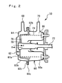
- Figure 2 is a vertical cross-sectional view that shows the configuration of the valve actuator. This view shows a cross-section of the valve actuator along the axis line of a drive rod 72 that is disposed in the center thereof.
- the valve actuator 30 includes a housing 60, the diaphragm 62, the drive rod 72, and a return spring 74.
- the housing 60 is formed as a hollow case by a metallic material or the like, and is assembled by fitting a cap 60b to an opening portion of a housing main body 60a.
- An annular flange portion 60c that sandwiches and holds the diaphragm 62 is formed at the portion where the housing main body 60a and the cap 60b fit together.
- the diaphragm 62 is formed from a flexible material such as rubber or resin, and is disposed inside the housing 60.
- the diaphragm 62 includes a bottomed cylindrical cup portion 62a arranged at a center part thereof, an annular thin-walled portion 62b that projects in a flange shape from the outer circumference of the cup portion 62a, and an annular fixed portion that is formed on the outer circumference of the thin-walled portion 62b.
- the cup portion 62a and the fixed portion 62c are formed as thick-walled portions that have a comparatively high rigidity.
- the fixed portion 62c is sandwiched and held by the flange portion 60c of the housing 60 across the entire circumference thereof.
- the thin-walled portion 62b has flexibility, and is formed as a region that can be bent and deformed.
- the diaphragm 62 defines the inside of the housing 60 into a high pressure chamber 64 and a low pressure chamber 66. These two pressure chambers are disposed on one side and the other side of the diaphragm 62, and are each formed in an airtight manner.
- the housing 60 is provided with two connection ports 68 and 70 that connect the high pressure chamber 64 and low pressure chamber 66 to outside, respectively.
- a differential pressure hereunder, referred to as "differential pressure in the forward direction”
- the diaphragm 62 bends and deforms towards the low pressure chamber 66 upon receiving the differential pressure in the forward direction, and is displaced in the axial direction together with the drive rod 72.
- the drive rod 72 is formed, for example, in the shape of a stepped rod.
- the proximal end side thereof is fixed to the cup portion 62a of the diaphragm 62 inside the housing 60.
- the distal end side of the drive rod 72 protrudes to outside from the housing main body 60a, and is connected to the WGV 28 via the link mechanism 32 shown in Figure 1 .
- the return spring 74 is composed by, for example, a coil spring, and is arranged in a compressed state inside the low pressure chamber 66.
- the return spring 74 constantly urges the cup portion 62a of the diaphragm 62 towards the high pressure chamber 64.
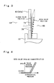
- FIG. 3 is an enlarged view of a principal portion in Figure 2 , which illustrates the vicinity of the reed valve in an enlarged manner.
- a vent hole 76 that penetrates the bottom of the cup portion 62a is formed in the diaphragm 62.
- the vent hole 76 constitutes a communication portion that links the high pressure chamber 64 and the low pressure chamber 66.
- the normally closed reed valve 78 is provided at the bottom of the cup portion 62a at a position that covers the vent hole 76 from the low pressure chamber 66 side.
- the reed valve 78 constitutes a pressure release valve of the present embodiment.
- the reed valve 78 is formed, for example, by a thin plate of metal or resin or the like that has elasticity (a spring property), and the proximal end side thereof is fixed to the bottom of the cup portion 62a.
- the distal end side of the reed valve 78 is retained in a closed valve position illustrated by the solid line in Figure 3 in a free state in which the reed valve 78 is not bent and deformed.
- the reed valve 78 blocks the vent hole 76 from the low pressure chamber 66 side, and hermetically blocks the communication portion between the high pressure chamber 64 and the low pressure chamber 66.
- FIG 4 is a characteristics diagram that illustrates the opening characteristics of the reed valve.
- the reed valve 78 is retained in the above-described closed valve position when a differential pressure in the forward direction is less than a predetermined valve opening pressure.
- a valve closing condition that is a condition in which a differential pressure in the forward direction is less than the valve opening pressure also includes a case in which a differential pressure in a direction that presses the diaphragm 62 towards the high pressure chamber 64 from the low pressure chamber 66 is generated (hereunder, referred to as "differential pressure in the backward direction").
- the distal end side of the reed valve 78 receives the differential pressure and changes shape so as to bend backwards, and changes position to the open valve position indicated by the dashed line in Figure 3 .
- the high pressure chamber 64 and the low pressure chamber 66 communicate through the vent hole 76.
- the pressure pipes 80 and 82, the negative pressure pump 84, and the pressure regulating valve 86 that are the drive system of the valve actuator 30 are described.
- the pressure pipe 80 on the high pressure side connects the high pressure chamber 64 (connection port 68) of the valve actuator 30 to the air intake passage 14.
- the connection position is set so as to be downstream of the compressor 24 and upstream of the throttle valve 18.
- intake air negative pressure of the engine 10 or a boost pressure (positive pressure) generated by the supercharger 20 is supplied to the high pressure chamber 64 through the pressure pipe 80.
- the air intake passage 14 constitutes a pressure source that supplies pressure to the high pressure chamber 64.
- the pressure pipe 82 on the low pressure side connects the low pressure chamber 66 (connection port 70) of the valve actuator 30 to the negative pressure pump 84.
- the negative pressure pump 84 for example, is composed of a mechanical pump that is driven by the engine 10, and constitutes a pressure source that supplies pressure (negative pressure) to the low pressure chamber 66 through the pressure pipe 82.
- a pressure regulating valve 86 that regulates a negative pressure supplied to the low pressure chamber 66 from the negative pressure pump 84 is provided in the pressure pipe 82.
- the pressure regulating valve 86 is composed, for example, of an electromagnetic drive-type three-way valve or the like. Based on a driving signal input from the ECU 50, some or all of negative pressure that is generated with the negative pressure pump 84 is released into the atmosphere. Accordingly, the pressure of the low pressure chamber 66 changes from a negative pressure generated by the negative pressure pump 84 to a pressure that is close to atmospheric pressure in accordance with the degree of opening of the pressure regulating valve 86. More specifically, when the pressure regulating valve 86 is fully opened, negative pressure generated with the negative pressure pump 84 is supplied as it is to the low pressure chamber 66. Further, when the pressure regulating valve 86 is fully closed, atmospheric pressure is supplied to the low pressure chamber 66.
- the pressure regulating valve 86 generates a differential pressure between the high pressure chamber 64 and the low pressure chamber 66, and also changes the direction and pressure value of the differential pressure.
- the air intake passage 14, the negative pressure pump 84, and the pressure regulating valve 86 constitute differential pressure generating means of the present embodiment.
- boost pressure control executed by the ECU 50 and operations of the valve actuator 30 in this control are described.
- the pressure regulating valve 86 changes the differential pressure to control the operating state (that is, the degree of opening of the WGV 28) of the valve actuator 30 based on the output of the intake air temperature sensor 38 and the boost pressure sensor 40.
- the boost pressure can be appropriately controlled as a result.
- the valve actuator 30 is stopped and the WGV 28 is maintained in a closed state.
- the pressure regulating valve 86 is fully closed, the pressure of the low pressure chamber 66 is increased as far as a pressure in the vicinity of atmospheric pressure, and the differential pressure in the forward direction is decreased.
- a resultant force that combines the differential pressure and the spring force of the return spring 74 acts in the direction of arrow B in Figure 2 on the diaphragm 62.
- the WGV 28 enters a closed state and normal supercharging operations are performed by the supercharger 20. Further, in this state, the differential pressure in the forward direction is maintained below the valve opening pressure of the reed valve 78 by the ECU 50. Accordingly, the reed valve 78 is retained in a closed state, and the high pressure chamber 64 and the low pressure chamber 66 are cut-off from each other.
- the valve actuator 30 when the temperature of intake air or the boost pressure is high, the valve actuator 30 is activated and causes the WGV 28 to open. Thereby, the boost pressure is restricted, and the occurrence of knocking or an abnormal increase in the boost pressure can be prevented.
- the pressure regulating valve 86 When activating the valve actuator 30, the pressure regulating valve 86 is opened to a large degree to increase the negative pressure acting on the low pressure chamber 66 and generate (increase) a differential pressure in the forward direction.
- a resultant force that combines the differential pressure and the spring force of the return spring 74 acts in the direction of arrow A in Figure 2 on the diaphragm 62.
- the thin-walled portion 62b bends and deforms so that the diaphragm 62 is displaced in the direction of arrow A in Figure 2 together with the drive rod 72.
- This displacement is transmitted to the WGV 28 via the link mechanism 32, and causes the WGV 28 to open.
- the ECU 50 When actuating the valve actuator 30 in a normal state in which pressure release control is not being executed, the ECU 50 maintains the pressure value of the differential pressure at a value that is less than the valve opening pressure of the reed valve 78 while also causing the diaphragm 62 to bend and deform by means of a differential pressure in the forward direction. More specifically, the ECU 50 maintains the degree of opening of the pressure regulating valve 86 in a state in which the degree of opening is moderately reduced from a fully open state, and supplies a negative pressure (pressure close to atmospheric pressure) that is higher than the negative pressure generated at the negative pressure pump 84 to the low pressure chamber 66.
- the differential pressure in the forward direction can be regulated to a pressure that is less than the valve opening pressure of the reed valve 78, and the reed valve 78 can be maintained in a closed state.
- valve actuator 30 that are described above (regarding the direction of action of a resultant force with respect to the diaphragm 62, and the behavior of the reed valve 78 and the like) can be implemented by, for example, appropriately setting the spring force of the return spring 74, the specifications of the pressure regulating valve 86, and the valve opening pressure of the reed valve 78 and the like.
- boost pressure control is merely one example that is illustrated according to the present embodiment, and the present invention is not limited thereto.
- a valve opening condition of the reed valve 78 (that is, a state in which the differential pressure in the forward direction becomes equal to or greater than the valve opening pressure of the reed valve 78) is realized by the pressure regulating valve 86, and the reed valve 78 is caused to open.
- the pressure regulating valve 86 is fully opened, negative pressure generated at the negative pressure pump 84 is supplied as it is to the low pressure chamber 66, and the differential pressure in the forward direction is increased to a pressure that is greater than or equal to the valve opening pressure.
- the pressure release temperature T1 is set to the upper limit of a temperature at which the diaphragm 62 is not damaged by an increase in the pressure of the high pressure chamber 64, and is previously stored in the ECU 50.
- a configuration is adopted that inhibits pressure release control when it is detected that the vehicle is moving based on the output of the vehicle speed sensor 44 (more specifically, when the vehicle speed is equal to or greater than a predetermined control inhibition speed V1).
- the control inhibition speed V1 is previously set as a minimum speed at which a cooling effect is obtained by a traveling wind. According to this configuration, since it is not necessary to execute pressure release control when a cooling effect is obtained from a traveling wind, the execution frequency of pressure release control that is control in an emergency situation can be reduced as much as possible.
- a configuration is adopted that inhibits pressure release control when an acceleration demand is detected based on the output of the accelerator opening sensor 42 (more specifically, when the accelerator opening is greater than or equal to a predetermined control inhibition opening A1).
- the control inhibition opening A1 is, for example, previously set in correspondence with an acceleration level at which there is a high possibility that boost pressure control will be executed. According to this configuration, execution of pressure release control can be prevented at the time of an acceleration operation, and thus drivability can be favorably maintained.
- the temperature t of the valve actuator 30 is estimated based on the operating information of the engine 10. More specifically, for example, the output of the engine is calculated based on the intake air amount and number of engine revolutions and the like, and the temperature t is calculated by estimation based on the output. The data necessary for this estimation processing is determined by experiment and the like, and is previously stored in the ECU 50. Thus, even without using a temperature sensor or the like, the temperature t of the valve actuator 30 can be easily acquired, and simplification of the system and a reduction in costs can be achieved. A configuration may also be adopted in which a detection result for the intake air temperature, the history of the engine output, the vehicle speed, and the like are reflected in the calculation value for the temperature t. Thus, the temperature t can be accurately estimated even in a case where the outside air temperature changes or when the vehicle is stopped while the engine is at a high temperature (a so-called "dead soak").
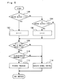
- FIG. 5 is a flowchart that illustrates control executed by the ECU according to Embodiment 1 of the present invention.
- the routine illustrated in Figure 5 is repeatedly executed during operation of the engine. According to this routine, first the temperature (estimated temperature) t of the valve actuator 30 is calculated utilizing the fact that the temperature of the actuator increases accompanying an increase in the engine output.
- the output of the engine is calculated based on the intake air amount and number of engine revolutions and the like, and it is determined whether or not the engine output is less than a predetermined low output determination value P1 (step 100). If the result determined in step 100 is "Yes", for example, the estimated temperature t is reduced by 1°C (step 102). In contrast, if the result determined in step 100 is "No", the ECU determines whether or not the engine output is greater than a predetermined high output determination value P2 (step 104). If the result determined in step 104 is "Yes", for example, the estimated temperature t is increased by 1°C (step 106).
- the low output determination value P1 and the high output determination value P2 are set as the minimum value and the maximum value of the engine output at which the actuator is maintained at a constant temperature, respectively, and are previously stored in the ECU 50.
- the temperature t of the valve actuator 30 can be estimated by the processing of steps 100 to 106. In this connection, this estimation processing is merely one example that is illustrated using the present routine, and the present invention is not limited thereto.
- the ECU determines whether or not the temperature t is greater than the aforementioned pressure release temperature T1, and whether or not the vehicle speed is less than the aforementioned control inhibition speed V1 (step 108). If the results determined in step 108 are both "Yes", the ECU determines whether or not the accelerator opening is less than the aforementioned control inhibition opening A1 (step 110). When these three determined results (steps 108 and 110) are all "Yes", the ECU executes the pressure release control and opens the reed valve 78 (step 112).
- step 108 and 110 If any of the aforementioned three results (steps 108 and 110) is "No", there is the possibility that the temperature of the valve actuator 30 has not risen to the extent that requires pressure release control, or that the vehicle speed is great enough to generate traveling wind, or that boost pressure control is performed at acceleration. Accordingly, in this case, the ECU does not execute the pressure release control, and executes control for normal time that includes the boost pressure control (step 114).
- the differential pressure in the forward direction is increased to a pressure that is greater than the valve opening pressure by the pressure regulating valve 86, so that the reed valve 78 can be opened.
- pressure can be released from the high pressure chamber 64 towards the low pressure chamber 66, and it is thus possible to prevent gas inside the high pressure chamber 64 from thermally expanding and damaging the diaphragm 62. Accordingly, the heat resistance property of the valve actuator 30 can be improved, and even when driving the WGV 28 in the vicinity of the exhaust system that becomes a high temperature, the valve actuator 30 can be stably operated.
- the vent hole 76 and reed valve 78 and the like for pressure release can be housed inside the housing 60 that is blocked off from the outside.
- the vent hole 76 and reed valve 78 and the like for pressure release can be housed inside the housing 60 that is blocked off from the outside.
- foreign matter such as dust and moisture can be reliably prevented from entering the housing 60 from outside. Accordingly, even when a mechanism for pressure release is mounted, an actuator with high reliability can be realized.
- the vent hole 76 is provided in the diaphragm 62 and is opened and closed by the reed valve 78 with a simple structure
- a mechanism for pressure release can be easily realized without mounting, for example, parts that form a passage for pressure release or a complex valve apparatus or the like in the valve actuator 30.
- the reed valve 78 can be easily opened by merely changing the direction or pressure value of the differential pressure. Therefore, the overall actuator can have a small size and a light weight, and assembly thereof can be performed efficiently.
- the air intake passage 14 that is a first pressure source is connected to the high pressure chamber 64
- the negative pressure pump 84 that is a second pressure source is connected to the low pressure chamber 66
- negative pressure is regulated by the pressure regulating valve 86. Therefore, different pressures can be supplied to the high pressure chamber 64 and the low pressure chamber 66, respectively, and a differential pressure can be efficiently generated between the high pressure chamber 64 and the low pressure chamber 66. Further, the direction and pressure value of the differential pressure can be accurately controlled by the pressure regulating valve 86.
- steps 100 to 106 shown in Figure 5 illustrate a specific example of temperature acquiring means according to claims 1 and 9.
- steps 108 and 112 illustrate a specific example of pressure release means according to claims 1 to 4
- step 114 illustrates a specific example of actuator control means according to claims 1 to 4.
- step 108 illustrates a specific example of drive time release inhibiting means according to claim 7
- step 110 illustrates a specific example of acceleration time release inhibiting means according to claim 8.
- Embodiment 2 of the present invention is described referring to Figure 6 to Figure 10 .
- a feature of the present embodiment is that the structure of the reed valve and the drive system of the valve actuator are different to those employed in Embodiment 1.
- the same reference numerals are used to designate components that are the same as in the above-described Embodiment 1, and a description of such components is omitted below.
- FIG. 7 is a vertical cross-sectional view that illustrates the structure of the valve actuator.
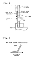
- Figure 8 is an enlarged view of a principal portion in Figure 7 that illustrates the vicinity of a reed valve in an enlarged manner.
- Figure 9 is a characteristics diagram that illustrates the opening characteristics of the reed valve.
- a valve actuator 90 similarly to Embodiment 1, includes the housing 60, the diaphragm 62, the high pressure chamber 64, the low pressure chamber 66, the drive rod 72, the return spring 74, and the vent hole 76, and also includes a reed valve 92 that is a normally-closed type of pressure release valve.
- the reed valve 92 is provided at a position that covers the vent hole 76 from the high pressure chamber 64 side.
- the reed valve 92 enters a free state and is retained in a closed valve position, and blocks the vent hole 76 from the high pressure chamber 64 side.
- the reed valve 92 is configured so as to open when a differential pressure in the backward direction arises and the valve opening condition is satisfied, and thereby open the vent hole 76.
- FIG. 6 is an overall configuration diagram for describing the system configuration of Embodiment 2 of the present invention.
- the drive system of the valve actuator 90 is provided with an electromagnetic drive-type switching valve 94 that is controlled by the ECU 50.
- the switching valve 94 is constituted by, for example, a three-port, two-position switching valve that has two inflow ports and one outflow port, and is connected to a position partway along the pressure pipe 80. More specifically, one inflow port of the switching valve 94 is connected to the air intake passage 14 via an upstream portion 80a of the pressure pipe 80, and the other inflow port is connected to the negative pressure pump 84. Further, the downstream port of the switching valve 94 is connected to the connection port 68 of the valve actuator 90 via a downstream portion 80b of the pressure pipe 80.
- the switching valve 94 can be switched to either of positions A and B shown in Figure 6 in accordance with a control signal input from the ECU 50.
- the connection port 68 (high pressure chamber 64) of the valve actuator 90 is connected to the air intake passage 14 when the switching valve 94 is switched to position A, and is connected to the negative pressure pump 84 when the switching valve 94 is switched to position B.
- the switching valve 94 constitutes another pressure regulating valve that is used in combination with the pressure regulating valve 86.
- the air intake passage 14, the negative pressure pump 84, the pressure regulating valve 86, and the switching valve 94 constitute differential pressure generating means.
- the degree of opening of the pressure regulating valve 86 is increased to increase the differential pressure in the forward direction and thereby cause the diaphragm 62 to bend and deform due to a resultant force in the direction of arrow A.
- the reed valve 92 is maintained in a closed state. Accordingly, similarly to Embodiment 1, the ECU 50 can execute boost pressure control.
- the ECU 50 switches the switching valve 94 to position B and sets the degree of opening of the pressure regulating valve 86 to a degree of opening that is at least not fully open (halfway open or a fully closed state).
- a negative pressure of the negative pressure pump 84 is supplied as it is to the high pressure chamber 64
- a pressure that is higher than the negative pressure of the pump is supplied to the low pressure chamber 66.
- a differential pressure in the backward direction arises between the two pressure chambers, and a valve opening condition is realized with respect to the reed valve 92.
- the reed valve 92 opens, pressure can be released via the vent hole 76.
- the reed valve 92 covers the vent hole 76 from the high pressure chamber 64 side, when actuating the diaphragm 62 it is possible to prevent the pressure in the low pressure chamber 66 from transiently increasing and damaging the thin-walled portion 62b of the diaphragm 62 or the like. More specifically, when the pressure in the high pressure chamber 64 is rapidly increased, in some cases an operation by the pressure regulating valve 86 that decreases the pressure in the low pressure chamber 66 does not occur quickly enough to counteract the rapid increase in pressure, and the diaphragm 62 is displaced towards the low pressure chamber 66 in a state in which the pressure in the low pressure chamber 66 is high.
- the reed valve 92 is opened by a differential pressure in the backward direction, and the pressure in the low pressure chamber 66 can be released to the high pressure chamber 64 side. More specifically, even when operating the valve actuator 90 at a high speed, the diaphragm 62 can be allowed to change shape while releasing pressure from the low pressure chamber 66, and the thin-walled portion 62b and the like can be protected from damage.
- Figure 10 is a flowchart that illustrates control executed by the ECU according to Embodiment 2 of the present invention.
- the routine illustrated in Figure 10 is repeatedly executed during operation of the engine. According to this routine, processing is first performed to estimate the temperature t of the valve actuator 90 and determine the temperature and vehicle speed (steps 200 to 208) by performing similar processing as in steps 100 to 108 in Embodiment 1 ( Figure 5 ).
- step 208 When the result determined at step 208 is "Yes”, the switching valve 94 is switched to position B and the aforementioned pressure release control is executed to open the reed valve 92 (step 210). Further, when the result determined at step 208 is "No”, the switching valve 94 is switched to position A and normal control including boost pressure control is executed (step 212).
- steps 200 to 206 in Figure 10 illustrate a specific example of temperature acquiring means according to claims 1 and 9.
- steps 208 and 210 illustrate a specific example of pressure release means according to claims 1 to 3, and 5.
- Step 212 illustrates a specific example of actuator control means according to claims 1 and 5.
- Step 208 illustrates a specific example of drive time release inhibiting means according to claim 7.
- valve actuators 30 and 90 that have the high pressure chamber 64 and the low pressure chamber 66.
- the present invention is not limited thereto.
- the present invention may also be applied to an actuator that has only one pressure chamber and which is configured to bend and deform a diaphragm by means of a differential pressure between the pressure inside the pressure chamber and an external atmospheric pressure.
- the vent hole 76 is provided in the diaphragm 62 as a communication portion at which the high pressure chamber 64 and the low pressure chamber 66 communicate.
- a communication portion may be composed by a through hole that is provided at a site (for example, the drive rod 72 or the like) other than the diaphragm, or a tube or pipe or the like that is connected between the housing main body 60a and the cap 60b outside the actuator.
- a configuration is adopted in which the vent hole 76 and the reed valve 78 or 92 are provided in the valve actuators 30 and 90, and the reed valve 78 or 92 is opened by pressure release control.
- the present invention does not necessarily require a structure such as a communication portion or a pressure release valve. More specifically, according to the present invention, a configuration may be adopted in which, without providing these structures, for example, a pressure that is supplied to a pressure chamber from a pressure source is decreased by pressure release means (pressure release control).
- a configuration is adopted which uses the air intake passage 14 and the mechanical negative pressure pump 84 as pressure sources.
- a pressure source of the present invention is not limited thereto and, for example, a configuration may be adopted which uses an electrically-driven pump or the exhaust passage 16 as a pressure source.
- the present invention is not limited thereto and, for example, a variable type pump apparatus that allows a generated pressure to be changed by the ECU without using a pressure regulating valve or the like may be employed, and the differential pressure generating means may be constituted by the pump apparatus.
- the WGV 28 is taken as an example of a movable mechanism that is driven by the valve actuator 30 or 90.
- the present invention is not limited thereto, and the present invention is applicable to an arbitrary movable mechanism that is mounted in the internal combustion engine and driven by an actuator.
Landscapes
- Engineering & Computer Science (AREA)
- Chemical & Material Sciences (AREA)
- Combustion & Propulsion (AREA)
- Mechanical Engineering (AREA)
- General Engineering & Computer Science (AREA)
- Supercharger (AREA)
Applications Claiming Priority (1)
| Application Number | Priority Date | Filing Date | Title |
|---|---|---|---|
| PCT/JP2010/052866 WO2011104831A1 (ja) | 2010-02-24 | 2010-02-24 | 内燃機関の制御装置 |
Publications (1)
| Publication Number | Publication Date |
|---|---|
| EP2541016A1 true EP2541016A1 (de) | 2013-01-02 |
Family
ID=44506278
Family Applications (1)
| Application Number | Title | Priority Date | Filing Date |
|---|---|---|---|
| EP10776069A Withdrawn EP2541016A1 (de) | 2010-02-24 | 2010-02-24 | Steuervorrichtung für einen verbrennungsmotor |
Country Status (5)
| Country | Link |
|---|---|
| US (1) | US20110225968A1 (de) |
| EP (1) | EP2541016A1 (de) |
| JP (1) | JP4952849B2 (de) |
| CN (1) | CN102227549A (de) |
| WO (1) | WO2011104831A1 (de) |
Families Citing this family (7)
| Publication number | Priority date | Publication date | Assignee | Title |
|---|---|---|---|---|
| JP6112299B2 (ja) * | 2013-06-14 | 2017-04-12 | 三菱自動車工業株式会社 | エンジンの制御装置 |
| GB2519164A (en) * | 2013-10-14 | 2015-04-15 | Gm Global Tech Operations Inc | Method of controlling the pressure of a turbocharger |
| EP3105432A4 (de) * | 2014-02-11 | 2017-08-23 | Borgwarner Inc. | Korrosionsbeständiges pneumatisches stellglied |
| CN104100363A (zh) * | 2014-07-28 | 2014-10-15 | 康跃科技股份有限公司 | 差压式气动执行器装置 |
| DE102014217456B3 (de) * | 2014-09-02 | 2015-08-06 | Continental Automotive Gmbh | Verfahren zur Ermittlung eines Ansteuersignals für den Aktuator des Wastegates eines Abgasturboladers eines Kraftfahrzeugs |
| DE102016122045B4 (de) | 2015-11-30 | 2022-09-29 | Cummins Inc. | WASTEGATE- und MOTOR-ANORDNUNG sowie Verfahren zum Betreiben eines Motors |
| DE102019003909A1 (de) * | 2019-06-03 | 2020-12-03 | Daimler Ag | Betätigungseinrichtung zum Betätigen eines Ventilelements eines Abgasturboladers |
Family Cites Families (29)
| Publication number | Priority date | Publication date | Assignee | Title |
|---|---|---|---|---|
| GB1240091A (en) * | 1970-01-06 | 1971-07-21 | Ford Motor Co | Spark advance retard device for an internal combustion engine |
| JPS5554634A (en) * | 1978-10-16 | 1980-04-22 | Nissan Motor Co Ltd | Apparatus for actuating waste gate valve of internal combustion engine with exhaust turbosupercharger |
| US4237076A (en) * | 1979-03-29 | 1980-12-02 | Schmelzer Corporation | Two stage vacuum break |
| US4403538A (en) * | 1980-09-02 | 1983-09-13 | The Garrett Corporation | Turbocharger control actuator |
| FR2515730A1 (fr) * | 1981-11-05 | 1983-05-06 | Renault | Dispositif perfectionne de commande de la pression de suralimentation d'un moteur turbocompresse permettant d'ameliorer la reponse dynamique |
| JPS60178931A (ja) * | 1984-02-24 | 1985-09-12 | Nissan Motor Co Ltd | 排気タ−ボチヤ−ジヤの過給圧制御装置 |
| US4566867A (en) * | 1984-07-02 | 1986-01-28 | Alberto Bazan | Dual diaphragm pump |
| US5063744A (en) * | 1988-10-06 | 1991-11-12 | Toyota Jidosha Kabushiki Kaisha | Actuator for controlling intake pressure in sequential turbo-system |
| US5168707A (en) * | 1989-11-21 | 1992-12-08 | Toyota Jidosha Kabushiki Kaisha | Internal combustion engine with a dual turbocharger system |
| US5154058A (en) * | 1991-06-11 | 1992-10-13 | Toyota Jidosha Kabushiki Kaisha | Internal combustion engine with a dual turbocharger system |
| US5294090A (en) * | 1992-11-25 | 1994-03-15 | Orbit Valve Company | Valve snubber |
| US5392691A (en) * | 1993-07-06 | 1995-02-28 | Indian Head Industries, Inc. | Stone shield for air brake actuator with welded yoke |
| US5727529A (en) * | 1994-01-14 | 1998-03-17 | Walbro Corporation | Pressure control valve for a fuel system |
| JP3661280B2 (ja) * | 1996-06-19 | 2005-06-15 | 株式会社デンソー | 温度式膨張弁 |
| JPH1136877A (ja) | 1997-07-18 | 1999-02-09 | Toyota Motor Corp | 負圧アクチュエータ |
| US20010037724A1 (en) * | 2000-03-08 | 2001-11-08 | Schumacher Mark S. | System for controlling hydraulic actuator |
| GB0111681D0 (en) * | 2001-05-11 | 2001-07-04 | Holset Engineering Co | Turbo charger with waste gate |
| US6490960B1 (en) * | 2001-07-11 | 2002-12-10 | Xerox Corporation | Muscle-emulating PC board actuator |
| JP2004092735A (ja) * | 2002-08-30 | 2004-03-25 | Ricoh Elemex Corp | ガス圧力調整器 |
| KR100582884B1 (ko) * | 2004-09-14 | 2006-05-25 | 삼성전자주식회사 | 써멀 액츄에이션 펌프 |
| JP4419894B2 (ja) | 2005-03-28 | 2010-02-24 | 株式会社デンソー | 内燃機関のウエストゲートバルブ制御装置 |
| US8197231B2 (en) * | 2005-07-13 | 2012-06-12 | Purity Solutions Llc | Diaphragm pump and related methods |
| DE102005039772A1 (de) * | 2005-08-22 | 2007-03-08 | Prominent Dosiertechnik Gmbh | Magnetdosierpumpe |
| WO2007030750A1 (en) * | 2005-09-09 | 2007-03-15 | Board Of Trustees Of The University Of Illinois | Dual chamber valveless mems micropump |
| CN100510344C (zh) * | 2005-12-05 | 2009-07-08 | 奇瑞汽车股份有限公司 | 废气旁通阀控制装置 |
| US7922147B2 (en) * | 2007-01-03 | 2011-04-12 | Zurn Industries, Llc | Diaphragm with segmented insert |
| US7726232B2 (en) * | 2007-02-26 | 2010-06-01 | Pendotech | Diaphragm pump liner for critical process applications |
| JP2009024502A (ja) * | 2007-07-17 | 2009-02-05 | Isuzu Motors Ltd | 排気バイパスバルブ |
| DE102007055630A1 (de) * | 2007-11-21 | 2009-05-28 | Bosch Mahle Turbo Systems Gmbh & Co. Kg | Ladeeinrichtung |
-
2010
- 2010-02-24 EP EP10776069A patent/EP2541016A1/de not_active Withdrawn
- 2010-02-24 JP JP2010540977A patent/JP4952849B2/ja not_active Expired - Fee Related
- 2010-02-24 CN CN2010800018664A patent/CN102227549A/zh active Pending
- 2010-02-24 US US12/994,946 patent/US20110225968A1/en not_active Abandoned
- 2010-02-24 WO PCT/JP2010/052866 patent/WO2011104831A1/ja not_active Ceased
Non-Patent Citations (1)
| Title |
|---|
| See references of WO2011104831A1 * |
Also Published As
| Publication number | Publication date |
|---|---|
| WO2011104831A1 (ja) | 2011-09-01 |
| JP4952849B2 (ja) | 2012-06-13 |
| JPWO2011104831A1 (ja) | 2013-06-17 |
| CN102227549A (zh) | 2011-10-26 |
| US20110225968A1 (en) | 2011-09-22 |
Similar Documents
| Publication | Publication Date | Title |
|---|---|---|
| EP2541016A1 (de) | Steuervorrichtung für einen verbrennungsmotor | |
| CN101680382B (zh) | 用于对内燃机的进气系统进行诊断的诊断方法和装置 | |
| JP5680169B1 (ja) | 内燃機関の制御装置および制御方法 | |
| EP3406880B1 (de) | Wastegaste-ventil-steuerungsverfahren und steuerungsvorrichtung | |
| EP2864644B1 (de) | Ventil mit veränderbarem durchfluss für turbolader | |
| JP3613671B2 (ja) | 内燃機関の排気通路切換装置 | |
| EP3569847B1 (de) | Verfahren zur steuerung eines verbrennungsmotors und vorrichtung zur steuerung eines verbrennungsmotors | |
| JP2013096372A (ja) | 過給機付き内燃機関の制御装置 | |
| CN109751136B (zh) | 内燃机的控制装置 | |
| CN108463619A (zh) | 废气旁通阀的控制方法及控制装置 | |
| EP3279454B1 (de) | Steuerungsvorrichtung für verbrennungsmotor | |
| US20150240704A1 (en) | Supercharging apparatus for engine | |
| US20160003130A1 (en) | Motor vehicle and adaptation method | |
| JP5262543B2 (ja) | ダイヤフラムアクチュエータ | |
| JP4466518B2 (ja) | 過給機付きエンジンの制御装置 | |
| JP3942556B2 (ja) | 過給機付き内燃機関のウエストゲートバルブ制御装置 | |
| CN100476169C (zh) | 带有增压器的内燃机 | |
| JP4390790B2 (ja) | 過給機付き内燃機関のウエストゲートバルブ制御装置 | |
| JP2005054750A (ja) | ターボ過給エンジン | |
| JP5794796B2 (ja) | 内燃機関 | |
| JP6449661B2 (ja) | 内燃機関の負圧システム | |
| KR100391627B1 (ko) | 터보챠저의 부스트압력 제어장치 | |
| JP4499592B2 (ja) | 車両の排気ブレーキ装置 | |
| JP2018031283A (ja) | 内燃機関 | |
| JP2007170266A (ja) | 排気ターボ機構付エンジン |
Legal Events
| Date | Code | Title | Description |
|---|---|---|---|
| PUAI | Public reference made under article 153(3) epc to a published international application that has entered the european phase |
Free format text: ORIGINAL CODE: 0009012 |
|
| 17P | Request for examination filed |
Effective date: 20120210 |
|
| AK | Designated contracting states |
Kind code of ref document: A1 Designated state(s): AT BE BG CH CY CZ DE DK EE ES FI FR GB GR HR HU IE IS IT LI LT LU LV MC MK MT NL NO PL PT RO SE SI SK SM TR |
|
| STAA | Information on the status of an ep patent application or granted ep patent |
Free format text: STATUS: THE APPLICATION HAS BEEN WITHDRAWN |
|
| RAP1 | Party data changed (applicant data changed or rights of an application transferred) |
Owner name: TOYOTA JIDOSHA KABUSHIKI KAISHA |
|
| RIN1 | Information on inventor provided before grant (corrected) |
Inventor name: EIRAKU, AKIRA |
|
| 18W | Application withdrawn |
Effective date: 20130116 |