EP0172421A2 - Pumpe mit hin- und hergehendem Kolben - Google Patents
Pumpe mit hin- und hergehendem Kolben Download PDFInfo
- Publication number
- EP0172421A2 EP0172421A2 EP85109094A EP85109094A EP0172421A2 EP 0172421 A2 EP0172421 A2 EP 0172421A2 EP 85109094 A EP85109094 A EP 85109094A EP 85109094 A EP85109094 A EP 85109094A EP 0172421 A2 EP0172421 A2 EP 0172421A2
- Authority
- EP
- European Patent Office
- Prior art keywords
- plunger
- cam
- delivery
- displacement
- valve
- Prior art date
- Legal status (The legal status is an assumption and is not a legal conclusion. Google has not performed a legal analysis and makes no representation as to the accuracy of the status listed.)
- Withdrawn
Links
- 238000006073 displacement reaction Methods 0.000 claims abstract description 86
- 230000007246 mechanism Effects 0.000 claims abstract description 50
- 238000003825 pressing Methods 0.000 claims description 47
- 239000007788 liquid Substances 0.000 claims description 46
- 239000012530 fluid Substances 0.000 claims description 39
- 230000001174 ascending effect Effects 0.000 claims description 16
- 230000033001 locomotion Effects 0.000 claims description 13
- 230000005540 biological transmission Effects 0.000 claims description 5
- 230000007423 decrease Effects 0.000 claims description 5
- 238000010586 diagram Methods 0.000 description 10
- 230000009471 action Effects 0.000 description 6
- 238000013461 design Methods 0.000 description 5
- 238000000034 method Methods 0.000 description 5
- 230000010349 pulsation Effects 0.000 description 5
- 238000004891 communication Methods 0.000 description 3
- 238000005260 corrosion Methods 0.000 description 3
- 230000007797 corrosion Effects 0.000 description 3
- 230000000694 effects Effects 0.000 description 3
- RTAQQCXQSZGOHL-UHFFFAOYSA-N Titanium Chemical compound [Ti] RTAQQCXQSZGOHL-UHFFFAOYSA-N 0.000 description 2
- 239000000919 ceramic Substances 0.000 description 2
- 238000001816 cooling Methods 0.000 description 2
- 230000003111 delayed effect Effects 0.000 description 2
- 229910000856 hastalloy Inorganic materials 0.000 description 2
- 238000004519 manufacturing process Methods 0.000 description 2
- 239000003921 oil Substances 0.000 description 2
- 230000002093 peripheral effect Effects 0.000 description 2
- 229910001220 stainless steel Inorganic materials 0.000 description 2
- 239000010935 stainless steel Substances 0.000 description 2
- 229910052719 titanium Inorganic materials 0.000 description 2
- 239000010936 titanium Substances 0.000 description 2
- 238000012546 transfer Methods 0.000 description 2
- 238000013459 approach Methods 0.000 description 1
- 230000008859 change Effects 0.000 description 1
- 238000010276 construction Methods 0.000 description 1
- 230000003247 decreasing effect Effects 0.000 description 1
- 230000001050 lubricating effect Effects 0.000 description 1
- 239000010687 lubricating oil Substances 0.000 description 1
- 239000000463 material Substances 0.000 description 1
- 230000004048 modification Effects 0.000 description 1
- 238000012986 modification Methods 0.000 description 1
- 230000008569 process Effects 0.000 description 1
- 238000005086 pumping Methods 0.000 description 1
- 239000007787 solid Substances 0.000 description 1
- 238000011144 upstream manufacturing Methods 0.000 description 1
Images



Classifications
-
- F—MECHANICAL ENGINEERING; LIGHTING; HEATING; WEAPONS; BLASTING
- F04—POSITIVE - DISPLACEMENT MACHINES FOR LIQUIDS; PUMPS FOR LIQUIDS OR ELASTIC FLUIDS
- F04B—POSITIVE-DISPLACEMENT MACHINES FOR LIQUIDS; PUMPS
- F04B7/00—Piston machines or pumps characterised by having positively-driven valving
- F04B7/0042—Piston machines or pumps characterised by having positively-driven valving with specific kinematics of the distribution member
- F04B7/0053—Piston machines or pumps characterised by having positively-driven valving with specific kinematics of the distribution member for reciprocating distribution members
-
- F—MECHANICAL ENGINEERING; LIGHTING; HEATING; WEAPONS; BLASTING
- F04—POSITIVE - DISPLACEMENT MACHINES FOR LIQUIDS; PUMPS FOR LIQUIDS OR ELASTIC FLUIDS
- F04B—POSITIVE-DISPLACEMENT MACHINES FOR LIQUIDS; PUMPS
- F04B1/00—Multi-cylinder machines or pumps characterised by number or arrangement of cylinders
- F04B1/04—Multi-cylinder machines or pumps characterised by number or arrangement of cylinders having cylinders in star- or fan-arrangement
- F04B1/0404—Details or component parts
- F04B1/0426—Arrangements for pressing the pistons against the actuated cam; Arrangements for connecting the pistons to the actuated cam
- F04B1/043—Hydraulic arrangements
-
- F—MECHANICAL ENGINEERING; LIGHTING; HEATING; WEAPONS; BLASTING
- F04—POSITIVE - DISPLACEMENT MACHINES FOR LIQUIDS; PUMPS FOR LIQUIDS OR ELASTIC FLUIDS
- F04B—POSITIVE-DISPLACEMENT MACHINES FOR LIQUIDS; PUMPS
- F04B11/00—Equalisation of pulses, e.g. by use of air vessels; Counteracting cavitation
- F04B11/005—Equalisation of pulses, e.g. by use of air vessels; Counteracting cavitation using two or more pumping pistons
- F04B11/0058—Equalisation of pulses, e.g. by use of air vessels; Counteracting cavitation using two or more pumping pistons with piston speed control
- F04B11/0066—Equalisation of pulses, e.g. by use of air vessels; Counteracting cavitation using two or more pumping pistons with piston speed control with special shape of the actuating element
-
- F—MECHANICAL ENGINEERING; LIGHTING; HEATING; WEAPONS; BLASTING
- F04—POSITIVE - DISPLACEMENT MACHINES FOR LIQUIDS; PUMPS FOR LIQUIDS OR ELASTIC FLUIDS
- F04B—POSITIVE-DISPLACEMENT MACHINES FOR LIQUIDS; PUMPS
- F04B9/00—Piston machines or pumps characterised by the driving or driven means to or from their working members
- F04B9/02—Piston machines or pumps characterised by the driving or driven means to or from their working members the means being mechanical
- F04B9/04—Piston machines or pumps characterised by the driving or driven means to or from their working members the means being mechanical the means being cams, eccentrics or pin-and-slot mechanisms
- F04B9/042—Piston machines or pumps characterised by the driving or driven means to or from their working members the means being mechanical the means being cams, eccentrics or pin-and-slot mechanisms the means being cams
-
- F—MECHANICAL ENGINEERING; LIGHTING; HEATING; WEAPONS; BLASTING
- F16—ENGINEERING ELEMENTS AND UNITS; GENERAL MEASURES FOR PRODUCING AND MAINTAINING EFFECTIVE FUNCTIONING OF MACHINES OR INSTALLATIONS; THERMAL INSULATION IN GENERAL
- F16H—GEARING
- F16H53/00—Cams or cam-followers, e.g. rollers for gearing mechanisms
- F16H53/02—Single-track cams for single-revolution cycles; Camshafts with such cams
Definitions
- This invention relates to a cam mechanism for driving reciprocating machines and to a constant volume pulsation-free reciprocating pump utilizing said cam mechanism.
- Reciprocating pumps perform pumping action consisting in the suction and delivery of liquid by the reciprocating motion of a plunger, piston or the like (hereinafter referred to collectively as a plunger) in a cylinder.
- the plunger pump as compared with others, withstands very high pressure and is superior in volumetric efficiency, so that it has been widely used in various fields.
- the delivery action of reciprocating pumps is intermittent and the delivery rate varies to a great extent, causing the so-called pulsation. If the delivery rate is not constant at any moment, as described above, various inconveniences arise. Particularly, it cannot be put to use in process plants or other facilities which require a constant volume of liquid to be fed at all times.
- the reciprocating pump comprises a liquid pressing chamber, a cylinder, and a plunger axially slidably installed in the cylinder to allow its one end to come in and out of the pressing chamber.
- the pressing chamber communicates on one hand with a liquid suction port via a suction valve allowing the passage of only liquid flowing into the pressing chamber and on the other hand with a delivery port via a delivery valve allowing the passage of only liquid flowing out of the pressing chamber.
- ball valves and poppet valves have been used as such suction valves and delivery valves. This type of valve performs an opening and closing action, that is, it is opened by liquid pressure and closed by gravitation; thus, it is a so-called check valve allowing the passage of liquid only in one direction.
- materials for the valve body suitable for the handling of corrosive liquid include stainless steel, ceramics, titanium, and Hastelloy.
- Stainless steel cannot be said to be almighty concerning corrosion resistance, while ceramics, titanium and Hastelloy are too light in weight to rely on gravitation for the closing of the valve.
- Even if a spring is to be built in it would be very difficult to obtain a spring designed to meet both requirements for corrosion resistance and spring constant.
- the valve opening and closing action could be dull or, at times, the valve could not move at all owing to the viscosity of liquid.
- a spring In the case of driving by using a cam mechanism, a spring is generally used for the returning of the plunger.
- a spring As a characteristic of a spring, there is a difference in pressure between the time the spring is expanded and the time it is contracted; thus, to match with all operating conditions it is inevitable to use a considerably strong pressure, leading to the consumption of unnecessary energy and, moreover, durability has to be taken into account.
- An object of this invention is to provide a reciprocating pump which is free from pulsation in the delivery rate and capable of feeding liquid always at a constant rate.
- This invention is also intended to provide a cam mechanism which can be used in such a reciprocating machine as a reciprocating pump.
- Another object of this invention is to provide a valve driving device for reciprocating pumps which is capable of positively opening and closing a valve at required times accurately corresponding to the stroke of the plunger and which eliminates the aforesaid disadvantages of the prior art.
- a further object of this invention is to provide a plunger restoring device for reciprocating pumps which is simple in construction and which is capable of smoothly and positively imparting a restoring force to the plunger under any operating conditions.
- a cam mechanism comprises three plate cams fixed on a common shaft so that they are -spaced 120° apart from each other.
- Each plate cam has a contour such that its displacement diagram has an ascending region in which displacement increases as the angle of rotation increases and a descending region in which displacement decreases as the angle of rotation increases.
- At least either the ascending region or the descending region includes an accelerating section in which displacement acceleratingly changes, a uniform velocity section in which displacement linearly changes, and a decelerating section in which displacement deceleratingly changes.
- the sum of the displacement per unit angle of rotation in the accelerating section and the displacement per corresponding unit angle of rotation in the decelerating section is equal to the displacement per unit angle of rotation in the uniform velocity section.
- a reciprocating pump utilizing a cam mechanism comprises three plunger pumps whose delivery ports are connected to a common delivery pipe, and the cam mechanism interposed between a driving device and the plunger pumps.
- Each plunger pump comprises liquid suction and delivery ports, a cylinder having a pressing chamber communicating with said two ports, a plunger axially slidably installed in the cylinder to allow its one end to come in and out of the pressing chamber, and a cam follower rotatably supported on the other end of the plunger.
- the three cam followers respectively abut against the three plate cams of the cam mechanism.
- the cam mechanism is arranged as described above.
- at least either the ascending region or the descending region corresponding to the delivery stroke of the plunger includes an accelerating section in which displacement acceleratingly changes, a uniform velocity section in which displacement linearly changes, and a decelerating section in which displacement deceleratingly changes.
- the sum of the displacement per unit angle of rotation in the accelerating section and the displacement per corresponding unit angle of rotation in the decelerating section is equal to the displacement per unit angle of rotation in the uniform velocity section.
- the displacement per unit angle of rotation is constant irrespective of angle of rotation and hence of time, so far as at least either the ascending region or the descending region which corresponds thereto is concerned. Therefore, in a reciprocating pump utilizing such cam mechanism, the combined delivery rate by the three plungers is constant irrespective of time.
- a cam mechanism according to this invention is utilized in a driving system for three reciprocating machines in this manner, during at least the advancing stroke or the retracting stroke of the reciprocating machine, the combined stroke per unit angle of rotation of the cam shaft or per unit time can be maintained constant at all times.
- the combined delivery rate of three plunger pumps can be maintained constant at all times.
- a driving device for reciprocating pumps is characterized by comprising a spring urging a suction valve in the valve closing direction, a cam operatively associated with the driving device of the plunger to open the suction valve against the pressing force of said spring during the time interval from the initial end to the terminal end of suction stroke of the plunger, and a cam operatively associated with the driving device of the plunger to cancel the pressing force of the spring acting on the delivery valve during the time interval from a little short of the delivery stroke of the plunger to the terminal end of the delivery stroke.
- the suction valve driving cam forcibly opens the suction valve against the pressing force of the spring, while the delivery valve driving cam effects forced closing of the delivery valve by the spring.
- the suction valve driving cam forces the suction valve to be closed by the pressing force of the spring.
- the delivery valve driving device cancels the pressing force of the spring acting on the delivery valve at the terminal end of the suction stroke, that is, a little short of the initial end of the delivery stroke.
- the respective timings of the opening and closing of the suction and delivery valves can be caused to coincide with desired points of time on the plunger stroke.
- Such effect is particularly useful for a reciprocating pump which feeds viscous liquid.
- a plunger restoring device for reciprocating pumps comprises fluid chambers for receiving fluid of predetermined pressure respectively installed at a plurality of plunger pumps, all the fluid chambers communicating with each other.
- Fluid being forced out of the fluid chambers of some plunger pumps included in those of the plurality of plunger pumps which are on their delivery stroke flows --distributively into the respective fluid chambers of the remaining plunger pumps which are on their suction stroke, thereby returning the corresponding plungers.
- the fluid being forced out of the corresponding chamber flows distributively into the chambers corresponding to other plungers which are retracting, thereby returning the corresponding plungers.
- the total amount of fluid in all chambers and in the pipeline allowing them to communicate with each other is substantially constant at all times, enabling the return movement of the plunger to be effected smoothly.
- the fluid pressure the lowest pressure required to return the plunger is sufficient and since it is constant at all times, there is no energy loss involved as there is in the case of using a spring.
- the surface pressure which acts on the cam follower during the return movement of the plunger is constant at all times, so that localized wear of the cam can be prevented.
- the present mechanism is rational.
- the ascending and decending regions are axially symmetrical.
- the displacement curves al-a3 are of the same shape, only differing in phase by 120° from each other, the manner of intersection being of two kinds alternating every 60° (indicated by I and II in the figure).
- the average delivery rate during the advance and return strokes is as indicated by a dash dot line.
- a dash dot line In the case of the so-called single acting triple type having three plungers spaced a crank angle of 120° apart from each other, the situation is as shown in Fig. 3.
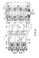
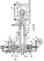
- a reciprocating pump comprises three plunger pumps driven by a cam mechanism 10 .
- the cam mechanism 10 includes a cam shaft 13 rotatably supported in bearings 12 housed in a cam box 11, and three axially spaced plate cams 14 fixed on the cam shaft so that the angle of attachment differs successively by 120°.
- Each plunger pump comprises a liquid pressing chamber 2 1 , a cylinder 22, and a plunger 23 axially slidably installed in the cylinder 22 to allow its one end to come in and out of the pressing chamber 21.
- the pressing chamber 21 is formed in a head block 24 positioned at the end of the cylinder 22 and communicates on the one hand with a liquid suction port 26 through a suction valve 25 which allows passage of only fluid flowing into the pressing chamber 21 and on the other hand with a delivery port 28 through a delivery valve 27 which allows passage of only fluid flowing out of the pressing chamber 21.
- the delivery ports 28 lead to a common conduit or delivery pipe (not shown).
- the cylinder 22 is attached to a cylinder case 30 fixed to the cam box 11. That is, the cylinder 22 and head block 24 are clamped by bolts 32 between the cylinder case 30 and a locking plate 31.
- the other end of the plunger 23 is coaxially integrally connected to a guide piston 33 axially slidably extending in the cylinder case 30. Rotatably supported at the end of the guide piston 33 is a cam follower 34.
- an annular chamber 39 is defined around the plunger 23 by the end surface 37 of the cylinder 22 and the end surface 38 of the guide piston 33.
- the chamber 39 communicates with a hole 40 formed in the cylinder case 30.
- the hole 40 is connected through a pipeline to a pressure fluid source such as an accumulator or a refill making use of a spring piston.
- a pressure fluid source such as an accumulator or a refill making use of a spring piston.
- Such returning force may be imparted by a spring, as well-known in the art.
- the same function can be attained also by an arrangement wherein all the chambers communicate with each other through a pipeline, with one end of the pipeline being connected to said pressure fluid source and the other end being closed.
- an oil pump as the pressure fluid source and install a relief valve at the other end of the pipeline.
- the reciprocating pump of the aforesaid arrangement operates as follows.
- Fig. 5 corresponds to a state in which the angle of rotation 6 in the displacement diagarm of Fig. 1 is zero.
- a first plunger as indicated by the displacement curve a1
- Second and third plungers will perform the aforesaid movement as they are delayed successively by 120°.
- the first 60° duration I it will be seen that when the first plunger is on the accelerating forward stroke, the second plunger is on the uniform velocity stroke as indicated by the displacement curve a2 and the third plunger, as indicated by the displacement curve a3, is on the decelerating return stroke.
- the first plunger enters the uniform velocity forward stroke, while the second plunger is on the decelerating return stroke and the third plunger on the accelerrating return stroke.
- the uniform velocity stroke of one plunger and the combined return stroke of the remaining two plungers alternate every 60°.
- each plate cam is such that the sum of displacement Ah2 per unit angle of rotation in the accelerating section of the displacement diagram and displacement Ah2 per correponding unit angle of rotation in the decelerating section is equal to displacement AH per unit angle of rotation in the uniform velocity section.
- AQ Aq1 + Aq2 holds, and the delivery rate of the reciprocating pump is always constant.
- the fluid for returning the plungers since the fluid for returning the plungers only moves to and fro between the three chambers 39 with its total amount remaining unchanged, nor increased or decreased theoretically, the opposite ends of the pipeline 15 may be closed.
- a pump of minimum capacity may be provided to compensate for such loss of fluid.
- the pressurized fluid source in addition to a pump it is possible to use an accumulator or a refill utilizing a spring piston.
- the three chambers 39 corresponding to the three plungers 23 communicate with each other through the pipeline 15 connected to holes 40.
- One end of the pipeline 15 is connected to a pressure source 16 such as an oil pump or accumulator, and the other end of the pipeline 15 communicates with a relief valve 17 (not necessary where the pressure source is an accumulator).
- a pressure source 16 such as an oil pump or accumulator
- the other end of the pipeline 15 communicates with a relief valve 17 (not necessary where the pressure source is an accumulator).
- the chambers 39 are always full of pressurized fluid.
- This pressurized fluid acts on the end surface 38 of the guide piston 33, producing a returning force which tends to move the guide piston 33 and plunger 23 to the right as viewed in the figure.
- the area of the end surface 38 and the pressure of the pressurized fluid may be so determined as to impart the irreducible minimum of returning force for return stroke to the plunger 23.
- any fluid pressure necessary for optimum forward movement can be quickly and easily imparted;
- a fluid pressure corresponding to the delivery pressure of liquid exerted by the plunger can be imparted by operating the fluid pressure, leakage of liquid from the cylinder can be reduced. For example, if a pressure which is half the delivery pressure of liquid is imparted to the liquid in the chamber, leakage can be reduced to less than half the value which is involved when the liquid is exposed to the atmosphere. Further, in this case, if the plunger is lubricated by using a suitable lubricating oil as the liquid for returning the plunger, this will contribute much to improving the durability of the constant volume pump;
- the suction valve 25 positioned between the liquid suction port 26 and the pressing chamber 21 comprises a valve head 42 formed conical on one end of a valve stem 41, and an annular valve seat 43 cooperating therewith.
- the valve stem 41 extends through a hole in the valve seat 43 and has a threaded portion 44 on the other end thereof.
- the threaded portion 44 has threadedly mounted threron a spring seat 45 and a cam abutting nut 46.
- the valve stem 41 is urged by a spring 48 disposed between the spring seat 45 and a locking joint 47 to cause the valve head 42 to abut against the valve seat 43.
- the locking joint 47 is threadedly inserted in the head block 24 and provides a communication passage 49 between the suction valve 25 and the suction port 26.
- the valve seat 43 has a plurality of guides 50 for radially guiding the valve head 42.
- a lever 52 pivotally connected at one end to the locking plate 31 by a pin 51 is formed at the other end with a pawl 54 cooperating with a suction valve driving cam 53 and at its intermediate portion with a projection 55 cooperating with a cam abutting nut 46 (Fig. 8).
- a support shaft 56 carrying the cam 53 is rotatably supported between a pair of brackets 57 and is operatively connected to the cam shaft 13 of the cam mechanism by a transmission device (not shown) comprising.sprockets and a chain. That is, when the cam shaft 13 is rotated one revolution, the support shaft 56 is also rotated one revolution.
- the contour of the suction valve driving cam 53 comprises a large diameter portion 58 extending along substantially half the circumference of the cam 53 corresponding to the suction stroke of the plunger 23 and a small diameter portion 59 extending along the remaining substantially half the circumference of the cam 53 corresponding to the delivery stroke of the plunger 23.
- the large diameter portion 58 includes a slope portion 60 smoothly continuous with the small diameter portion 59 and corresponding to the terminal end of the suction stroke, i.e., the initial end of the delivery stroke. Further, in the portion corresponding to the terminal end of the suction stroke, i.e., the initial end of the delivery stroke, the two portions 58 and 59 are discontinuous, forming a step 6 1 .
- the delivery valve 27 positioned between the pressing chamber.21 and the liquid delivery port 28, as shown in Fig. 9, comprises a conical valve head 62 and an annular valve seat 63 cooperating therewith.
- the extension 64 of the valve head 62 is provided with a plurality of radially extending guide ribs 65.
- the guide ribs 65 are adapted to come in slide contact with the hole of the valve seat 63 to radially guide the valve head 62.
- Extending through a locking joint 67 threadedly inserted in the head block 24 to provide a communication passage 66 between the delivery valve 27 and the delivery port 28 is a valve stem 68 which is coaxial with the valve head 62 and axially slidable.
- the valve stem 68 has a spring seat 69 threadedly attached to one end thereof.
- a hanger plate 70 attached to the extension 31' of the locking plate 31 has an adjusting, screw 7 1 threadedly inserted therein.
- a spring 72 interposed between the adjusting screw 71 and the spring seat 69 urges the valve stem 68 downward as viewed in the figure. Thus, normally the action of this spring 72 causes the valve stem 68 to press the valve head 62 against the valve seat 63.
- a lever 74 supported at one end in the extension 31' by a pin 73 is formed at the other end thereof with a pawl 76 cooperating with a delivery valve driving cam 75 and at its intermediate portion with a projection 77 abutting against the spring seat 69 (Fig. 11).
- a support shaft 78 carrying a cam 75 thereon is rotatably supported between a pair of brackets 79 and is operatively associated with the cam shaft 13 of the cam mechanism by a transmission device (not shown) comprising sprockets and a chain. That is, when the cam shaft 13 is rotated one revolution, the support shaft 78 is also rotated one revolution.
- the contour of the delivery valve driving cam 75 comprises a large diameter portion 80 extending along substantially half the circumference of the cam 75 corresponding to the delivery stroke of the plunger 23, and a small diameter portion 81 extending along the remaining substantially half the circumference of the cam 75 correponding to the suction stroke of the plunger 23.
- the large diameter portion 80 is greater than the small diameter portion 81 by an angle ⁇ .
- the suitable range of 6 is determined by the rpm of the cam 75 and the delivery pressure of the pump.
- the initial portion 82 of the large diameter portion 80 is smoothly continuous with the small diameter portion 81. Further, in the portion corresponding to the terminal end of the delivery stroke, i.e., the initial end of the suction stroke, the two portions 80 and 81 are discontinuous, forming a step 83.
- Figs. 12 and 13 illustrate a mechanism for finely adjusting the timing of the opening and closing of each valve.
- This finely adjusting mechanism is provided separately for each of the suction and delivery valves and is used to make independent fine ajustments of the timing of the opening and closing of each valve. Since these mechanisms are of the same arrangement, the one for the suction valve 25 will be taken up for description.
- Fig. 12 shows the end of the support shaft 56 (Fig. 6) having the suction valve driving cam 53 attached thereto.
- a sprocket 85 operatively connected to a sprocket 84 on the cam shaft 13 of the cam mechanism by a chain is loosely mounted on the support shaft 56.
- the sprocket 85 has an adjuster plate 86 integral therewith, said adjuster plate 86 being adapted to be clamped by bolts 88 to a plate 87 keyed to the support shaft 56. Holes 89 in the plate 87 through which the bolts 88 extend are circumferentially elongated.
- the adjuster plate 86 has a notch 91 to clear a pin 90 fixed to the plate 87, and a pair of opposed adjusting screws 92 are threadedly inserted on both circumferential sides of the notch 91 with the pin 90 interposed therebetween.
- the angular position of the adjuster plate 86 with respect to the plate 87 can be changed by loosening the bolts 88 and turning the adjusting screws 92 to change their axial positions.
- this is the operation of relatively changing the angle of rotation of the support shaft 56 with respect to the cam shaft 13, or the operation of changing the timing of the opening and closing of the suction valve 25 with respect to the stroke of the plunger 23. That is, this makes it possible to simultaneously adjust the timing of the opening and closing of three cams (in the case of a triple pump).
- the timing of the opening and closing of the delivery valve 27 with respect to the stroke of the plunger 23 can be changed by a finely adjusting mechanism of the same arrangement.
- the outer peripheral surface 93 of the adjuster plate 86 is formed with a notch and if the outer peripheral surface 94 of the plate 86 is correspondingly formed with graduations of predetermined spacing, the finely adjusting operation can be
- displacement curves a, b and c in Fig. 14 refer to the plunger driving cam 14, the suction valve driving cam 53 and the delivery valve driving cam 75, respectively.
- the delivery stroke which continues from this state until the cam shaft 13 is rotated through 180° will be considered.
- the suction valve driving cam 53 produces no displacement during this interval of 180°.
- the pawl 53 of the lever 52 continues to engage the small diameter portion 59 of the cam 53, giving no displacement to the valve stem 41. Therefore, the suction valve 25 remains closed.
- the delivery valve driving cam 75 maintains displacement hc during this interval of 180°.
- the pawl 76 of the lever 74 continues to engage the large diameter portion 80 of the cam 75. Therefore, the delivery valve 27 remains released from the pressing force of the spring 72.
- the pressure in the pressing chamber 21 rises with the movement of the plunger 23 and as soon as the pressures on opposite sides of the valve head 62 are balanced, the liquid pushes the valve head 62 open and flows from the pressing chamber 21 to the delivery port 28.
- the resistance at this time is only the slight weight
- the step portion 83 of the delivery valve driving cam 75 disengages the pawl 76 of the lever 74 from the large diameter portion 80, whereupon the pawl falls down to the small diameter portion 81.
- the lever 74 decends and the valve stem 68 is moved downward as viewed in Fig, 9 by the action of the spring 72 to press the valve head 62 against the valve seat 63.
- the delivery valve 27 is firmly closed in an instant.
- the pawl 54 of the lever 52 is disengaged from the small diameter portion 59 of the suction valve driving cam 53 and instead starts to engage the slope portion 60. This is the start of the suction stroke ranging over the next 180°.
- the suction valve driving cam 53 causes the lever 52 to gradually raise the valve stem 41, moving the valve head 42 away from the valve seat 43 against the pressing force of the spring 48.
- the suction valve 25 is opened, allowing the liquid to flow from the suction port 26 into the pressing chamber 21.
- the cam 59 maintains the pawl 54 of the lever 52 at displacement hb during the suction stroke, keeping the suction valve 25 open.
- the delivery valve driving cam 75 raises the lever 74 at a position a little (the amount of said 6 expressed in terms of angle of rotation) short of the terminal end of the delivery stroke. Since the lever 74 is contacted at its projection 77 with the spring seat 69, the valve stem 68 is moved upward as viewed in the figure against the pressing force of the spring 72, so that the pressing force of the spring 72 acting on the valve head 62 is removed.
- the liquid delivered by the previous delivery stroke remains at a predetermined pressure and the liquid which is present upstream of the valve head 62, i.e., in the pressing chamber 21 is at the negative pressure produced by the suction stroke; thus, the valve head 62 remains seated on the valve seat 63 because of the difference between the pressures across the valve head 62.
- the pawl 54 of the lever 52 is disengaged from the large diameter portion 58 of the suction valve driving cam 53 by the step portion 61 and falls down onto the small diameter portion 59, bringing the lever 52 back to its Fig. 6 state.
- the suction valve 25 is instantly closed by the pressing force of the spring 48.
- the displacement curve b of the suction valve driving cam 53 remains at the displacement zero and the displacement curve c of the delivery valve driving cam 75 maintains the displacement hc.
- the suction valve driving cam 53 maintains the displacement hc and the delivery valve driving cam 75 initially makes no displacement but at a position which is 8 short of the terminal end of the suction stroke it makes again the displacement hc.
- the timing of such cam is attained in that, as described above, the cam shaft 13 of the cam mechanism for reciprocating the plunger 23 is operatively associated with the support shafts 56 and 78 for supporting the cams 53 and 75 by a transmission devide comprising, e.g., sprockets and a chain.
- a transmission devide comprising, e.g., sprockets and a chain.
- the springs 48 and 72 are disposed outside the valve mechanisms as described above, there is no limitation due to the spring storing space as there is when they are stored in the valve mechanism, so that it becomes easier to design a spring which is effective to ensure quick and positive closing of the valve. Further, since these springs 48 and 72 do not come in contact with liquid, even in the case of handling corrosive liquid it is only necessary to give consideration to corrosion resistance in connection with only the valve head and the valve seat so far as the valve mechanisms are concerned.
- valve driving device of this invention is employed in a constant volume pump adapted to prevent pulsation of the delivery rate, as described above, it will contribute to improving the volumetric constancy of the pump by ensuring the accurate timing of the opening and closing of the suction and delivery valves.
- the embodiment described herein is intended to control the opening and closing of the suction and delivery valves by cams operatively associated with the plunger driving cams.
- cams operatively associated with the plunger driving cams.
- the operative association of the timing of the opening and closing of the suction and delivery valves with the movement of the plungers can be made also by the following arrangements in addition to the aforesaid embodiment:
- the invention may be embodied in the form of the cam mechanism with more than three cam plates.
- the reciprocating pump may likewise comprise more than three cylinder-plunger arrangements.
Landscapes
- Engineering & Computer Science (AREA)
- General Engineering & Computer Science (AREA)
- Mechanical Engineering (AREA)
- Reciprocating Pumps (AREA)
Applications Claiming Priority (6)
| Application Number | Priority Date | Filing Date | Title |
|---|---|---|---|
| JP162590/84 | 1984-07-31 | ||
| JP16259084A JPS6140467A (ja) | 1984-07-31 | 1984-07-31 | カム機構および該カム機構を用いた定量ポンプ |
| JP169701/84 | 1984-08-13 | ||
| JP16970184A JPS6149177A (ja) | 1984-08-13 | 1984-08-13 | 往復ポンプのプランジヤ戻し装置 |
| JP16980784A JPS6149181A (ja) | 1984-08-14 | 1984-08-14 | 往復ポンプの弁駆動装置 |
| JP169807/84 | 1984-08-14 |
Publications (2)
| Publication Number | Publication Date |
|---|---|
| EP0172421A2 true EP0172421A2 (de) | 1986-02-26 |
| EP0172421A3 EP0172421A3 (de) | 1986-07-16 |
Family
ID=27322022
Family Applications (1)
| Application Number | Title | Priority Date | Filing Date |
|---|---|---|---|
| EP85109094A Withdrawn EP0172421A3 (de) | 1984-07-31 | 1985-07-19 | Pumpe mit hin- und hergehendem Kolben |
Country Status (3)
| Country | Link |
|---|---|
| US (1) | US4687426A (de) |
| EP (1) | EP0172421A3 (de) |
| CA (1) | CA1254443A (de) |
Cited By (3)
| Publication number | Priority date | Publication date | Assignee | Title |
|---|---|---|---|---|
| EP0265591A3 (en) * | 1986-10-27 | 1989-03-22 | Fuji Techno Kogyo Kabushiki Kaisha | Reciprocating pump |
| CN100424343C (zh) * | 2006-06-22 | 2008-10-08 | 上海交通大学 | 确定无冲击恒流量双柱塞泵凸轮轮廓形状的方法 |
| FR3044052A1 (fr) * | 2015-11-25 | 2017-05-26 | Exel Ind | Pompe d'alimentation d'un systeme d'application d'un produit de revetement liquide |
Families Citing this family (18)
| Publication number | Priority date | Publication date | Assignee | Title |
|---|---|---|---|---|
| US5368451A (en) * | 1991-06-04 | 1994-11-29 | Hammond; John M. | Metering pump |
| US5364242A (en) * | 1992-11-25 | 1994-11-15 | Pharmacia Deltec, Inc. | Pump apparatus and method including double activation pump apparatus |
| US5733105A (en) * | 1995-03-20 | 1998-03-31 | Micropump, Inc. | Axial cam driven valve arrangement for an axial cam driven parallel piston pump system |
| EP0817916A4 (de) | 1995-03-20 | 2000-05-24 | Micropump Inc | Pumpe mit mehreren kolben |
| US5718570A (en) * | 1995-03-20 | 1998-02-17 | Micropump Corporation | Rotary control valve for a piston pump |
| US5707212A (en) * | 1995-05-12 | 1998-01-13 | Matthews; Ernest L. | Apparatus for precisely controlling the feeding of viscous and non-viscous liquid products into a packaging machine |
| US6109878A (en) * | 1998-04-13 | 2000-08-29 | Micropump, Inc. | System and a method for velocity modulation for pulseless operation of a pump |
| GB9815272D0 (en) * | 1998-07-14 | 1998-09-09 | Lucas Ind Plc | Positive displacement pumps |
| DE19932078A1 (de) * | 1999-07-12 | 2001-02-01 | Kamat Pumpen Gmbh & Co Kg | Vorrichtung zum Pumpen großer Fördermengen einer Flüssigkeit |
| GB0229367D0 (en) * | 2002-12-17 | 2003-01-22 | Delphi Tech Inc | Fuel Pump |
| EP2719947B1 (de) * | 2005-04-12 | 2016-08-03 | Zilkha Biomass Power I LLC | Integriertes Biomasse-Gasturbinensystem mit einer Zyklonbrennkammer |
| US7927082B2 (en) * | 2005-12-05 | 2011-04-19 | Gth Water Systems, Inc. | Highly efficient durable fluid pump and method |
| CN102094777A (zh) * | 2011-01-27 | 2011-06-15 | 北京清博华科技有限公司 | 制备液相色谱柱塞泵 |
| US9003955B1 (en) * | 2014-01-24 | 2015-04-14 | Omax Corporation | Pump systems and associated methods for use with waterjet systems and other high pressure fluid systems |
| GB201502686D0 (en) * | 2015-02-18 | 2015-04-01 | Finishing Brands Uk Ltd | High pressure pump |
| US10808688B1 (en) | 2017-07-03 | 2020-10-20 | Omax Corporation | High pressure pumps having a check valve keeper and associated systems and methods |
| EP4127527A1 (de) | 2020-03-24 | 2023-02-08 | Hypertherm, Inc. | Hochdruckdichtung für ein flüssigkeitsstrahlschneidsystem |
| KR20230005840A (ko) | 2020-03-30 | 2023-01-10 | 하이퍼썸, 인크. | 다기능 접속 종방향 단부들을 갖는 액체 제트 펌프를 위한 실린더 |
Family Cites Families (13)
| Publication number | Priority date | Publication date | Assignee | Title |
|---|---|---|---|---|
| GB152644A (en) * | 1919-10-10 | 1921-12-05 | Michel Zack | Piston pump for raising liquids which easily evaporate at low temperature and are under vacuum |
| US1723874A (en) * | 1924-11-20 | 1929-08-06 | Courtaulds Ltd | Pump and like device for controlling the rate of delivery of fluids |
| GB350171A (en) * | 1930-05-02 | 1931-06-11 | Hathorn Davey And Company Ltd | Improvements in or relating to pumps and other machines or engines employing the three-throw cycle |
| US2010377A (en) * | 1930-12-26 | 1935-08-06 | Cincinnati Milling Machine Co | Hydraulic power unit |
| GB533961A (en) * | 1939-08-22 | 1941-02-25 | Arthur John Rowledge | Improvements in or relating to reciprocating pumps |
| GB582259A (en) * | 1944-07-06 | 1946-11-11 | Midwest Hydraulics Inc | Improvements in hydraulic pumps |
| FR1263952A (fr) * | 1960-05-04 | 1961-06-19 | Dispositif hydraulique de rappel des pistons, dans les pompes hydrauliques à pistons multiples | |
| SE327098B (de) * | 1968-01-12 | 1970-08-10 | Linson Instr Ab | |
| DE1800142A1 (de) * | 1968-10-01 | 1970-04-16 | Haldor Frederik Axel Topsoe Fa | Pulsationsfrei dosierende Kolbenpumpe mit zwei oder mehreren parallel verbundenen Pumpenraeumen fuer inkompressible Medien,insbesondere Fluessigkeiten |
| CH541130A (de) * | 1971-07-06 | 1973-08-31 | Hoffmann La Roche | Dosierpumpe |
| GB1481043A (en) * | 1974-06-10 | 1977-07-27 | Paterson Candy Int | Non-pulsing pumping apparatus |
| DE2706685A1 (de) * | 1977-02-17 | 1978-08-24 | Smirnov | Kolbenpumpe |
| US4556371A (en) * | 1983-07-18 | 1985-12-03 | Fmc Corporation | Constant flow positive displacement pump |
-
1985
- 1985-06-19 US US06/746,828 patent/US4687426A/en not_active Expired - Lifetime
- 1985-06-28 CA CA000485941A patent/CA1254443A/en not_active Expired
- 1985-07-19 EP EP85109094A patent/EP0172421A3/de not_active Withdrawn
Cited By (4)
| Publication number | Priority date | Publication date | Assignee | Title |
|---|---|---|---|---|
| EP0265591A3 (en) * | 1986-10-27 | 1989-03-22 | Fuji Techno Kogyo Kabushiki Kaisha | Reciprocating pump |
| CN100424343C (zh) * | 2006-06-22 | 2008-10-08 | 上海交通大学 | 确定无冲击恒流量双柱塞泵凸轮轮廓形状的方法 |
| FR3044052A1 (fr) * | 2015-11-25 | 2017-05-26 | Exel Ind | Pompe d'alimentation d'un systeme d'application d'un produit de revetement liquide |
| EP3173621A1 (de) * | 2015-11-25 | 2017-05-31 | Exel Industries | Förderpumpe für ein system zur aufbringung eines flüssigen beschichtungsprodukts |
Also Published As
| Publication number | Publication date |
|---|---|
| CA1254443A (en) | 1989-05-23 |
| EP0172421A3 (de) | 1986-07-16 |
| US4687426A (en) | 1987-08-18 |
Similar Documents
| Publication | Publication Date | Title |
|---|---|---|
| EP0172421A2 (de) | Pumpe mit hin- und hergehendem Kolben | |
| DE1776253B2 (de) | Vorrichtung zur drehzahl- und lastabhaengigen einspritzzeitpunktverstellung von kraftstoffeinspritzpumpen | |
| US3323461A (en) | Metering pump | |
| US5257605A (en) | Engine brake for a multicylinder internal combustion engine | |
| EP0063535A2 (de) | Brennstoffeinspritzpumpe mit einer Überlauf-Steuervorrichtung | |
| EP1536137B1 (de) | Kraftstoffpumpe für eine Brennkraftmaschine | |
| EP0265591B1 (de) | Pumpe mit oszillierender Bewegung | |
| GB2097483A (en) | Plunger pump for delivering a liquid particularly fuel in an internal combustion engine | |
| SE420521B (sv) | Brensleinsprutningspump for forbrenningsmotorer | |
| WO2006089558A1 (en) | Method and apparatus for lubricating cylinder surfaces in large diesel engines | |
| CN85105369A (zh) | 往复式液压泵 | |
| GB2051968A (en) | Pumping system for unstable fluids | |
| US4737085A (en) | Fuel injection pump for internal combustion engines | |
| GB2059516A (en) | Two-component Metering Pumps | |
| JPH01199097A (ja) | 潤滑装置 | |
| JPH0754115B2 (ja) | 往復ポンプ | |
| US5044899A (en) | Fuel pumping apparatus | |
| US5059096A (en) | Fuel pumping apparatus | |
| US3645648A (en) | Hydraulic pulse generator | |
| RU2063550C1 (ru) | Регулируемый насос | |
| DE102009026740A1 (de) | Hochdruckpumpe | |
| EP0421807B1 (de) | Schmieranlage und Pumpe | |
| US3390639A (en) | Fuel injection pump | |
| EP1435456B1 (de) | Hydraulische Pumpe | |
| SU170178A1 (de) |
Legal Events
| Date | Code | Title | Description |
|---|---|---|---|
| PUAI | Public reference made under article 153(3) epc to a published international application that has entered the european phase |
Free format text: ORIGINAL CODE: 0009012 |
|
| AK | Designated contracting states |
Kind code of ref document: A2 Designated state(s): AT BE CH DE FR GB IT LI LU NL SE |
|
| PUAL | Search report despatched |
Free format text: ORIGINAL CODE: 0009013 |
|
| AK | Designated contracting states |
Kind code of ref document: A3 Designated state(s): AT BE CH DE FR GB IT LI LU NL SE |
|
| 17P | Request for examination filed |
Effective date: 19870115 |
|
| 17Q | First examination report despatched |
Effective date: 19880121 |
|
| STAA | Information on the status of an ep patent application or granted ep patent |
Free format text: STATUS: THE APPLICATION HAS BEEN WITHDRAWN |
|
| 18W | Application withdrawn |
Withdrawal date: 19891204 |
|
| R18W | Application withdrawn (corrected) |
Effective date: 19891204 |
|
| RIN1 | Information on inventor provided before grant (corrected) |
Inventor name: YOSHIMURA, HIROICHIC/O FUJI TECH.KOGYO KK |