EP0172555A2 - Vice - Google Patents
Vice Download PDFInfo
- Publication number
- EP0172555A2 EP0172555A2 EP85110417A EP85110417A EP0172555A2 EP 0172555 A2 EP0172555 A2 EP 0172555A2 EP 85110417 A EP85110417 A EP 85110417A EP 85110417 A EP85110417 A EP 85110417A EP 0172555 A2 EP0172555 A2 EP 0172555A2
- Authority
- EP
- European Patent Office
- Prior art keywords
- clamping jaw
- threaded spindle
- guide
- clamping
- displaceable
- Prior art date
- Legal status (The legal status is an assumption and is not a legal conclusion. Google has not performed a legal analysis and makes no representation as to the accuracy of the status listed.)
- Granted
Links
Images





Classifications
-
- B—PERFORMING OPERATIONS; TRANSPORTING
- B25—HAND TOOLS; PORTABLE POWER-DRIVEN TOOLS; MANIPULATORS
- B25B—TOOLS OR BENCH DEVICES NOT OTHERWISE PROVIDED FOR, FOR FASTENING, CONNECTING, DISENGAGING, OR HOLDING
- B25B1/00—Vices
- B25B1/24—Details, e.g. jaws of special shape, slideways
- B25B1/2405—Construction of the jaws
- B25B1/2431—Construction of the jaws the whole jaw being pivotable around an axis perpendicular to the actioning direction of the vice
- B25B1/2436—Construction of the jaws the whole jaw being pivotable around an axis perpendicular to the actioning direction of the vice around a vertical axis
-
- B—PERFORMING OPERATIONS; TRANSPORTING
- B23—MACHINE TOOLS; METAL-WORKING NOT OTHERWISE PROVIDED FOR
- B23D—PLANING; SLOTTING; SHEARING; BROACHING; SAWING; FILING; SCRAPING; LIKE OPERATIONS FOR WORKING METAL BY REMOVING MATERIAL, NOT OTHERWISE PROVIDED FOR
- B23D51/00—Sawing machines or sawing devices working with straight blades, characterised only by constructional features of particular parts; Carrying or attaching means for tools, covered by this subclass, which are connected to a carrier at both ends
- B23D51/02—Sawing machines or sawing devices working with straight blades, characterised only by constructional features of particular parts; Carrying or attaching means for tools, covered by this subclass, which are connected to a carrier at both ends of beds; of guiding arrangements for work-tables or saw carriers; of frames
-
- B—PERFORMING OPERATIONS; TRANSPORTING
- B23—MACHINE TOOLS; METAL-WORKING NOT OTHERWISE PROVIDED FOR
- B23D—PLANING; SLOTTING; SHEARING; BROACHING; SAWING; FILING; SCRAPING; LIKE OPERATIONS FOR WORKING METAL BY REMOVING MATERIAL, NOT OTHERWISE PROVIDED FOR
- B23D51/00—Sawing machines or sawing devices working with straight blades, characterised only by constructional features of particular parts; Carrying or attaching means for tools, covered by this subclass, which are connected to a carrier at both ends
- B23D51/02—Sawing machines or sawing devices working with straight blades, characterised only by constructional features of particular parts; Carrying or attaching means for tools, covered by this subclass, which are connected to a carrier at both ends of beds; of guiding arrangements for work-tables or saw carriers; of frames
- B23D51/025—Sawing machines or sawing devices working with straight blades, characterised only by constructional features of particular parts; Carrying or attaching means for tools, covered by this subclass, which are connected to a carrier at both ends of beds; of guiding arrangements for work-tables or saw carriers; of frames of arrangements for guiding the saw blade
- B23D51/026—Sawing machines or sawing devices working with straight blades, characterised only by constructional features of particular parts; Carrying or attaching means for tools, covered by this subclass, which are connected to a carrier at both ends of beds; of guiding arrangements for work-tables or saw carriers; of frames of arrangements for guiding the saw blade by plural opposed guide surfaces
-
- B—PERFORMING OPERATIONS; TRANSPORTING
- B23—MACHINE TOOLS; METAL-WORKING NOT OTHERWISE PROVIDED FOR
- B23D—PLANING; SLOTTING; SHEARING; BROACHING; SAWING; FILING; SCRAPING; LIKE OPERATIONS FOR WORKING METAL BY REMOVING MATERIAL, NOT OTHERWISE PROVIDED FOR
- B23D51/00—Sawing machines or sawing devices working with straight blades, characterised only by constructional features of particular parts; Carrying or attaching means for tools, covered by this subclass, which are connected to a carrier at both ends
- B23D51/04—Sawing machines or sawing devices working with straight blades, characterised only by constructional features of particular parts; Carrying or attaching means for tools, covered by this subclass, which are connected to a carrier at both ends of devices for feeding, positioning, clamping, or rotating work
-
- B—PERFORMING OPERATIONS; TRANSPORTING
- B25—HAND TOOLS; PORTABLE POWER-DRIVEN TOOLS; MANIPULATORS
- B25B—TOOLS OR BENCH DEVICES NOT OTHERWISE PROVIDED FOR, FOR FASTENING, CONNECTING, DISENGAGING, OR HOLDING
- B25B1/00—Vices
- B25B1/20—Vices for clamping work of special profile, e.g. pipes
-
- B—PERFORMING OPERATIONS; TRANSPORTING
- B25—HAND TOOLS; PORTABLE POWER-DRIVEN TOOLS; MANIPULATORS
- B25B—TOOLS OR BENCH DEVICES NOT OTHERWISE PROVIDED FOR, FOR FASTENING, CONNECTING, DISENGAGING, OR HOLDING
- B25B1/00—Vices
- B25B1/24—Details, e.g. jaws of special shape, slideways
- B25B1/2405—Construction of the jaws
- B25B1/2457—Construction of the jaws with auxiliary attachments
-
- B—PERFORMING OPERATIONS; TRANSPORTING
- B27—WORKING OR PRESERVING WOOD OR SIMILAR MATERIAL; NAILING OR STAPLING MACHINES IN GENERAL
- B27G—ACCESSORY MACHINES OR APPARATUS FOR WORKING WOOD OR SIMILAR MATERIALS; TOOLS FOR WORKING WOOD OR SIMILAR MATERIALS; SAFETY DEVICES FOR WOOD WORKING MACHINES OR TOOLS
- B27G5/00—Machines or devices for working mitre joints with even abutting ends
- B27G5/02—Machines or devices for working mitre joints with even abutting ends for sawing mitre joints; Mitre boxes
Definitions
- the invention relates to a vice with a manually operable threaded spindle, a non-displaceable relative to this and a displaceable clamping jaw, the latter being pivoted on a nut arranged on the threaded spindle about an axis perpendicular to the spindle axis.
- Such vices are known in many designs (see, for example, DE-PS 811 215, DE-PS 90 192, DE-PS 371 835 and DE-OS 32 22 699).
- workpieces can not only be clamped in parallel, i.e. fixed between clamping surfaces of the two clamping jaws running parallel to one another, but thanks to the pivoting clamping jaw, it is also possible to clamp workpieces with surfaces that run obliquely to one another, e.g. a wedge-shaped workpiece, so that its sloping surfaces lie snugly against the two jaws.
- the vice according to the invention is fastened to a worktop or the like by fixing the non-displaceable clamping jaw on the worktop, for example by means of screw clamps, the threaded spindle as a whole can nevertheless be pivoted with respect to the worktop and with respect to both clamping jaws, so that it is easily possible , ewindespindelgriff and to create the adjacent thereto workpiece legs even with an angular workpiece a sufficient clearance between the G without possible to dispense with the advantages of the described known vices takes, namely workpieces as to be able to clamp between an angle to each other extending clamping jaws both in parallel as well.
- the vice according to the invention is extremely simple.
- a preferred embodiment of the vice according to the invention is characterized by at least one guide rod which can be pushed parallel to the threaded spindle through guide channels in the clamping jaws.
- a guide rod is preferably provided on both sides of the threaded spindle. If the guide rods have a stop interacting with the one clamping jaw and they are dimensioned such that they are difficult to move in the guide channels of this clamping jaw, but the other guide jaw can easily slide on them, it cannot happen that when the vice is actuated one of the guide rods is pulled out of one of the clamping jaws.
- the clamping jaws can be manufactured particularly inexpensively and are easy to assemble if they have an upper and a lower part, which together form trough-shaped recesses, each with a pivot bearing, to form a through-channel for the threaded spindle or its extension, the manufacturing price thereby being further increased can lower that the two jaws are identical.
- the upper and lower part of a clamping jaw could be locked together using appropriately designed locking elements such as pins and bores.
- an embodiment is preferred in which the upper and lower part are connected by screws. If channels are provided for these screws in the upper part, in which the screw heads are countersunk, there is an additional advantage without further effort: If the clamping jaws are provided on their upper side with several insertion channels running parallel to the pivot axes, the latter being the latter the channels for inserting the screws can act, pins or other pin-shaped elements, such as screws, present in every workshop can be inserted into these channels, in order to be able to clamp workpieces between these pin-shaped elements which otherwise could not be clamped between the clamping jaws; for example, it is possible to place a round, oval or differently shaped disc, a hemisphere or the like on the clamping jaws between the pin-shaped elements and then to clamp the workpiece between these pin-shaped elements.
- the vice according to the invention can even be expanded into a machine tool if the clamping jaws have at least one guide channel on each side of the threaded spindle and on the side facing away from the non-displaceable clamping jaw a bracket for an additional unit is pushed onto the displaceable clamping jaw on the guide rods that can be pushed into the clamping jaws.
- This additional unit can be a drive motor for a drill, milling cutter or the like, with which a workpiece held between the clamping jaws can be machined.
- a tool holder on the displaceable clamping jaw, which supports the turning tool.
- the holder To the 1925aggre at-bracket g in the direction of a held between the jaws workpiece advance, it is further proposed to provide the holder with a passage opening for the threaded spindle and screwed onto the latter one is provided with an internal thread of the handle, from those Side of the bracket that faces away from the jaws. With this handle, the auxiliary unit holder can then be moved along the guide rods.
- the vice according to the invention can also be supplemented so that miter cuts can be carried out with it;
- guides for a saw blade can be placed on the clamping jaws and each pivotable about one of the insertion channels.
- the two clamping jaws are to be offset relative to one another in accordance with a desired miter angle. Even a common miter angle of 45 ° results in a considerable offset of the clamping jaws in this embodiment, especially with wide workpieces.
- a further addition to the vise for miter sawing does not show these disadvantages.
- a guide for a saw blade which can be attached to one of the clamping jaws, in particular the immovable clamping jaw, is provided, this guide having two pairs of rollers arranged at a distance from one another in the saw blade displacement direction and being rotatable about an axis parallel to the pivot axes.
- the jaw carrying the guide is equipped with a carrier element which is on at least one side of the jaw bearing eye offset downward from an upper edge of the clamping jaw for rotatably receiving the guide.
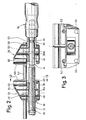
- a threaded spindle 12 provided with an axial stop 10 in the form of a snap ring or the like has an undulating extension 14 to which a handle 16 is attached.
- a threaded sleeve 18 provided with an internal thread is screwed onto the threaded spindle 12, while a sleeve 20 is seated on the spindle extension 14, which sleeve has a smooth longitudinal bore 24 with the exception of an inner collar 22.
- the inner collar 22 engages in a groove 26 of the spindle extension 14 so that the spindle extension 14 can be rotated in the sleeve 20, but the latter cannot be displaced in the axial direction relative to the threaded spindle 12.
- Both sleeves 18 and 20 have a transverse bore 18a or 20a for articulating a clamping jaw 30 or 32, which, as can be seen from FIGS. 1 and 2, are of identical design and comprise an upper part 34 and a lower part 36, each of which has one has trough-shaped recesses 38 and 40, which, when the clamping jaw is assembled, form a through-channel 42 for the threaded spindle 12 or the spindle extension 14, which widens towards both ends (see FIG. 1) by the clamping jaws relative to the threaded spindle and the spindle extension g 12 or 14 or to be able to pivot the threaded spindle together with the spindle extension relative to the two clamping jaws 30, 32.
- pivot pins 46 and 48 which are molded onto the upper part 34 and the lower part 36 and which engage in the corresponding transverse bore 18a or 20a (see FIG. 2).
- the jaws each have an insertion opening 50 in the lower part 36 on both sides of the threaded spindle 12 for inserting a clamp arm, in order to be able to fix the vice in particular on the immovable clamp 30 with the aid of two clamps on a worktop.
- guide channels 52 are provided in the upper part 34 on both sides of the threaded spindle, so that an alignment of the two clamping jaws such that their clamping surfaces 56 run parallel to one another can be ensured by guide rods 54 inserted into the latter.
- each clamping jaw has a plurality of insertion channels 60, some of which receive connecting screws 62, which are screwed into threaded bores of the lower parts 36, not shown, around the upper and lower parts of the Clamps hold together the heads of the connecting bolts insteckkanälen deep into the E are sunk 60th Therefore, what will be discussed later, pins or the like can also be inserted into the insertion channels 60 from above. Insert jaws.
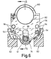
- FIGS. 5 and 6 show the vice shown in FIG. 1 with an additional handle 70, which has a nut 72 running on the threaded spindle 12 and an abutment 74, around an additional unit holder 76 according to FIG. 5 composed of plastic parts and pushed onto the guide rods 54 5 to be able to slide to the left against the action of compression springs 78 seated on the guide rods 54.
- an electric motor (not shown), provided with a chuck and similar to a hand drill, can be inserted and clamped with the help of the pipe clamp 80, while pins 84 can be inserted into the insertion channels 60 Allow jaws 30 and 32 to attach plastic parts 86, which are preferably of identical design.
- the plastic part 86 fastened on the non-displaceable clamping jaw 30 should be by means of two pins 84 are held, while FIG. 5 reveals that the plastic part 86 placed on the other clamping jaw 32 is pivotally attached.
- An opening 88 in the plastic parts 86 can serve to hold a tip bearing 90 for a workpiece in the plastic part on the left according to FIG.
- the plastic part 86 placed on the clamping jaw 32 can finally serve to hold or support a tool, so that the vice can be used as a type of lathe or for turning.
- a bed 92 is provided which, according to the invention, is designed as a trough-shaped receptacle for the vice, so that the clamping jaw 32 can be displaced along the bed 92 .
- the additional unit holder 76 has two pairs of guide channels 94 for the guide rods 54 and an elongated hole 96 for the passage of the threaded spindle 12, so that the additional unit holder 76 is attached to the guide rods 54 in two different height positions leaves.
- FIG. 7 shows how workpieces of any contour can be clamped with the aid of the vice according to the invention.
- dowel pins 98 are inserted into at least two insertion channels 60 of one clamping jaw and at least one insertion channel 60 of the other clamping jaw.
- an oval workpiece 100 can be securely clamped with four such clamping pins 98; the same would also apply to workpieces of a different shape - of course, these workpieces then sit over the two clamping jaws 30 and 32.
- FIGS. 8 and 9 finally show the vice which has been added to a miter saw device.
- Clamping jaws are fastened by means of fastening means (not shown in more detail) to top clamping jaws 102, which allow a bar 104 or the like to be mitred to be held above the clamping jaws 30, 32.
- fastening means not shown in more detail
- FIG 106 for the passage of a back saw 108.
- pins 110 of rotary disk-shaped saw blade guides 112 are inserted into the central insertion channels 60 of the two clamping jaws. The latter each carry two vertically extending axes 114, on which guide rollers 116 are attached.
- Each guide roller has a circumferential groove 118, the width of which is adapted to the height of the back 108a of the back saw 108, and the distance between the two axes 114 of each saw blade guide 112 is selected such that the back 108 fits straight between the two guide rollers 116.
- the length of the guide rollers 116 is dimensioned such that the cutting edge of the back saw 108 just touches the disks 112a of the saw blade guides 112 when all the guide rollers are seated on these disks. Then the back saw with its saw blade extends through the slots 106 of the top jaws 102.
- the immovable clamping jaw 30 is provided with an angular support element 120, the first leg 122 of which engages over the clamping surface 56 of the clamping jaw 30 and bores 124 for the guide rods 54 has.
- a second leg 126 of the carrier element 120 perpendicular to the first leg 122, rests on an upper side of the clamping jaw 30 and has a bore 128 which is aligned with the middle one of the insertion channels 60.
- the support element 120 is fixed by means of a screw 130 which can be inserted through the bore 128 and which has a self-tapping thread and thus anchors itself in the wall surfaces of the central insertion channel 60.
- a bearing eye 132 which is preferably set back with respect to the clamping surface 56 and downwards with respect to the upper edge thereof and has a bore 134 which is parallel to the pivot axes of the clamping jaws.
- an annular tooth surface 138 with tooth surfaces running radially to the bore 134 is provided around the bore 134.
- the bearing for the back saw 108 is supported by a cylindrical projection of this guide 140, which is rotatably mounted in the bore 134, with an annular collar 144 which overlaps the tooth surface 138 and which in turn also has radial tooth surfaces on a side facing the tooth surface 138 , so that the guide 140 can be locked in a rotationally fixed manner in the bearing eye 132 by means of these two interlocking toothings.
- a locking screw 146 is provided which overlaps the underside of the bearing eye 132 and is anchored in a threaded bore 148 of the cylindrical projection 142.
- two plate-like and parallel guide parts 150 extend upwards, which delimit a gap 152 with a central plane running through the axis of the bore 134.
- the back saw 108 is displaceably supported in the gap 152 by means of guide rollers 116 arranged axially parallel to the bore 134, which are rotatably held in pairs in the saw blade displacement direction in bearing bores 154 of the guide parts 150 at a distance from one another.
- Two guide rollers 116 arranged on opposite sides of the gap 152 form a pair, the spacing of which is selected such that the back saw 108 is guided correctly between these two guide rollers 116.
- the back saw 108 can start from one with the clamping surfaces 56 a position including a right angle can easily be rotated to an angle of well over 45 °, but only in the direction in which the distance between the back saw 108 and the displaceable clamping jaws 32 increases.
- To saw an angle complementary to this angle either the workpiece has to be reclamped or there is the possibility of moving the guide 140 into the bearing eye 132 arranged on the opposite side of the clamping jaw 30 and fixing it there accordingly.
- a step 156 is also provided in the first leg of the carrier element 122, which serves as a stop when the workpiece is clamped and prevents the workpiece from being clamped too deeply, so that it cannot be completely severed in the vertical direction.
- the vise can be used either with or without the guide rods 54, depending on the shape of the workpiece to be sawn, so that the workpiece can also be clamped with clamping jaws inclined or offset with respect to one another. It is only to be ensured that the cutting edge of the back saw 108 runs next to the movable clamping jaw 32, so that the saw jaws 32 are not sawed when the workpiece is sawed through.
Landscapes
- Mechanical Engineering (AREA)
- Engineering & Computer Science (AREA)
- Life Sciences & Earth Sciences (AREA)
- Wood Science & Technology (AREA)
- Forests & Forestry (AREA)
- Gripping Jigs, Holding Jigs, And Positioning Jigs (AREA)
- Sawing (AREA)
- Polymers With Sulfur, Phosphorus Or Metals In The Main Chain (AREA)
- Photoreceptors In Electrophotography (AREA)
- Transition And Organic Metals Composition Catalysts For Addition Polymerization (AREA)
- Crystals, And After-Treatments Of Crystals (AREA)
- Saccharide Compounds (AREA)
- Non-Silver Salt Photosensitive Materials And Non-Silver Salt Photography (AREA)
Priority Applications (1)
| Application Number | Priority Date | Filing Date | Title |
|---|---|---|---|
| AT85110417T ATE57643T1 (de) | 1984-08-22 | 1985-08-20 | Schraubstock. |
Applications Claiming Priority (2)
| Application Number | Priority Date | Filing Date | Title |
|---|---|---|---|
| DE3430814 | 1984-08-22 | ||
| DE3430814A DE3430814C2 (de) | 1984-08-22 | 1984-08-22 | Spannwerkzeug |
Publications (3)
| Publication Number | Publication Date |
|---|---|
| EP0172555A2 true EP0172555A2 (fr) | 1986-02-26 |
| EP0172555A3 EP0172555A3 (en) | 1986-05-28 |
| EP0172555B1 EP0172555B1 (fr) | 1990-10-24 |
Family
ID=6243593
Family Applications (1)
| Application Number | Title | Priority Date | Filing Date |
|---|---|---|---|
| EP85110417A Expired - Lifetime EP0172555B1 (fr) | 1984-08-22 | 1985-08-20 | Vice |
Country Status (3)
| Country | Link |
|---|---|
| EP (1) | EP0172555B1 (fr) |
| AT (1) | ATE57643T1 (fr) |
| DE (2) | DE3430814C2 (fr) |
Cited By (4)
| Publication number | Priority date | Publication date | Assignee | Title |
|---|---|---|---|---|
| EP0324057A3 (fr) * | 1987-12-29 | 1990-01-31 | Günter Horst Röhm | Etau pour machines |
| DE4202780A1 (de) * | 1992-01-31 | 1993-08-05 | Rheinmetall Gmbh | Antriebsteil einer grosskalibrigen mehrzweck-patrone und verwendung eines derartigen antriebsteiles zur herstellung unterschiedlicher patronenarten |
| EP0674962A1 (fr) * | 1994-03-31 | 1995-10-04 | Schefe, Ines | Dispositif pour la coupe en longueur de profilés creux |
| CN110653428A (zh) * | 2019-09-12 | 2020-01-07 | 淮阴工学院 | 一种新型机械式防倾斜板牙装置及其使用方法 |
Families Citing this family (2)
| Publication number | Priority date | Publication date | Assignee | Title |
|---|---|---|---|---|
| DE3744499A1 (de) * | 1987-12-30 | 1989-07-20 | Bessey & Sohn | Spanneinrichtung |
| DE19936453A1 (de) * | 1999-08-03 | 2001-02-08 | Bessey & Sohn | Spanneinrichtung für parallele und winklige Teile |
Family Cites Families (15)
| Publication number | Priority date | Publication date | Assignee | Title |
|---|---|---|---|---|
| DE90192C (fr) * | ||||
| BE524208A (fr) * | ||||
| US1328250A (en) * | 1919-08-06 | 1920-01-13 | Henry B Keiper | Combination-tool |
| US1425275A (en) * | 1921-05-12 | 1922-08-08 | Christian P Paulsen | Three-in-one clamp and vise combined |
| US1961036A (en) * | 1933-09-25 | 1934-05-29 | William E Boyle | Vise |
| DE729654C (de) * | 1940-12-21 | 1942-12-19 | Wilhelm Thienes | Schraubstock |
| GB638944A (en) * | 1948-01-29 | 1950-06-21 | Stanley Gartwaite Welbury | Improved machine vice |
| CH307069A (de) * | 1952-09-04 | 1955-05-15 | Seifert Paul | Schraubstock, insbesondere für Fräsmaschinen und Drehbänke. |
| DE1927198A1 (de) * | 1969-05-28 | 1970-12-03 | Hans Neuerer | Zusammensetzbarer Etagenstaender |
| US3741064A (en) * | 1970-07-10 | 1973-06-26 | Mfg Quenot Mabo | Mitre box |
| DE2504897C2 (de) * | 1975-02-06 | 1984-05-24 | Robert 5446 Engeln Wolff | Schraubstock |
| DE2722256C3 (de) * | 1977-05-17 | 1980-07-31 | Franz 8940 Memmingen Amschler | Schraubzwinge, die zum Aufnehmen verschiedenartiger Zubehörteile ausgebildet ist |
| DE2912832A1 (de) * | 1979-03-30 | 1980-10-09 | Bernstein Werkzeugfabrik Stein | Spannvorrichtung als zusatzvorrichtung fuer einen schraubstock o.dgl. spanngeraet |
| GB2101506B (en) * | 1981-06-18 | 1985-05-30 | Tekron Licensing Bv | Workbench vices |
| DE3244022C2 (de) * | 1982-11-27 | 1985-04-11 | Bessey & Sohn Gmbh & Co, 7000 Stuttgart | Spannvorrichtung zum Fixieren von im Winkel zueinander verlaufenden Werkstücken |
-
1984
- 1984-08-22 DE DE3430814A patent/DE3430814C2/de not_active Expired
-
1985
- 1985-08-20 AT AT85110417T patent/ATE57643T1/de not_active IP Right Cessation
- 1985-08-20 EP EP85110417A patent/EP0172555B1/fr not_active Expired - Lifetime
- 1985-08-20 DE DE8585110417T patent/DE3580216D1/de not_active Expired - Lifetime
Cited By (4)
| Publication number | Priority date | Publication date | Assignee | Title |
|---|---|---|---|---|
| EP0324057A3 (fr) * | 1987-12-29 | 1990-01-31 | Günter Horst Röhm | Etau pour machines |
| DE4202780A1 (de) * | 1992-01-31 | 1993-08-05 | Rheinmetall Gmbh | Antriebsteil einer grosskalibrigen mehrzweck-patrone und verwendung eines derartigen antriebsteiles zur herstellung unterschiedlicher patronenarten |
| EP0674962A1 (fr) * | 1994-03-31 | 1995-10-04 | Schefe, Ines | Dispositif pour la coupe en longueur de profilés creux |
| CN110653428A (zh) * | 2019-09-12 | 2020-01-07 | 淮阴工学院 | 一种新型机械式防倾斜板牙装置及其使用方法 |
Also Published As
| Publication number | Publication date |
|---|---|
| EP0172555B1 (fr) | 1990-10-24 |
| DE3430814C2 (de) | 1986-07-31 |
| DE3430814A1 (de) | 1986-03-06 |
| EP0172555A3 (en) | 1986-05-28 |
| ATE57643T1 (de) | 1990-11-15 |
| DE3580216D1 (de) | 1990-11-29 |
Similar Documents
| Publication | Publication Date | Title |
|---|---|---|
| EP2002943A1 (fr) | Supports de machines | |
| EP0117973A2 (fr) | Machine-outil modulaire de petites dimensions | |
| DE3831375A1 (de) | Spanneinrichtung | |
| DE3511498A1 (de) | Vorrichtung zur bearbeitung von pfosten oder sprossen fuer fenster oder tueren | |
| DE3333495A1 (de) | Drehbares zerspanungswerkzeug, insbesondere ausbohrkopf od. dgl. | |
| DE3026162C2 (de) | Vorrichtung zum Festspannen eines Holzklotzes zum exzentrischen oder Stay-log-Schälen | |
| DE3430496A1 (de) | Hilfsvorrichtung zum fraesen von schwalbenschwanznuten bei rechtwinklig zusammenzuzinkenden brettern | |
| EP0172555B1 (fr) | Vice | |
| EP0533093A2 (fr) | Moyens de serrage à variation continue | |
| DE19634156C1 (de) | Vorrichtung zum Handhaben einer Werkzeugmaschine | |
| EP0175011A1 (fr) | Outil de coupe rotatif en particulier tête de foreuse | |
| DE19640031C1 (de) | Frässchablone | |
| DE3842963A1 (de) | Werktisch fuer handwerkzeugmaschinen | |
| DE3918710C2 (de) | Gehrungssäge für Glashalteleisten | |
| DE4025440A1 (de) | Tischsaege | |
| EP0445363A1 (fr) | Dispositif de fraisage ou perçage | |
| DE8424815U1 (de) | Schraubstock | |
| DE2225136A1 (de) | Verbesserungen an Werkstück-Spannvorrichtungen | |
| DE29712584U1 (de) | Multifunktionales Kopier-Schneidesystem für holzbearbeitende Drehbank | |
| DE2230482C3 (de) | Um eine vertikale Achse drehbarer Obersupport für Drehmaschinen | |
| DE4027465A1 (de) | Vorrichtung zum halten von zu bearbeitenden werkstuecken | |
| DE3537992A1 (de) | Oberfraesenfuehrer fuer eine gitterartige zinkenfraeslehre | |
| DE3936883A1 (de) | Fraeskopf zur holzbearbeitung | |
| DE3134563A1 (de) | "bohrstaender fuer handbohrmaschinen" | |
| DE2705360B2 (de) | Werkzeughalter für Einstecharbeiten auf Drehmaschinen, insbesondere Bohrstange |
Legal Events
| Date | Code | Title | Description |
|---|---|---|---|
| PUAI | Public reference made under article 153(3) epc to a published international application that has entered the european phase |
Free format text: ORIGINAL CODE: 0009012 |
|
| AK | Designated contracting states |
Designated state(s): AT CH DE FR IT LI |
|
| PUAL | Search report despatched |
Free format text: ORIGINAL CODE: 0009013 |
|
| AK | Designated contracting states |
Kind code of ref document: A3 Designated state(s): AT CH DE FR IT LI |
|
| 17P | Request for examination filed |
Effective date: 19861127 |
|
| 17Q | First examination report despatched |
Effective date: 19871102 |
|
| GRAA | (expected) grant |
Free format text: ORIGINAL CODE: 0009210 |
|
| AK | Designated contracting states |
Kind code of ref document: B1 Designated state(s): AT CH DE FR IT LI |
|
| REF | Corresponds to: |
Ref document number: 57643 Country of ref document: AT Date of ref document: 19901115 Kind code of ref document: T |
|
| ITF | It: translation for a ep patent filed | ||
| REF | Corresponds to: |
Ref document number: 3580216 Country of ref document: DE Date of ref document: 19901129 |
|
| ET | Fr: translation filed | ||
| PLBE | No opposition filed within time limit |
Free format text: ORIGINAL CODE: 0009261 |
|
| STAA | Information on the status of an ep patent application or granted ep patent |
Free format text: STATUS: NO OPPOSITION FILED WITHIN TIME LIMIT |
|
| ITTA | It: last paid annual fee | ||
| 26N | No opposition filed | ||
| PGFP | Annual fee paid to national office [announced via postgrant information from national office to epo] |
Ref country code: AT Payment date: 19920818 Year of fee payment: 8 |
|
| PGFP | Annual fee paid to national office [announced via postgrant information from national office to epo] |
Ref country code: CH Payment date: 19920821 Year of fee payment: 8 |
|
| PGFP | Annual fee paid to national office [announced via postgrant information from national office to epo] |
Ref country code: FR Payment date: 19920827 Year of fee payment: 8 |
|
| PG25 | Lapsed in a contracting state [announced via postgrant information from national office to epo] |
Ref country code: AT Effective date: 19930820 |
|
| PG25 | Lapsed in a contracting state [announced via postgrant information from national office to epo] |
Ref country code: LI Effective date: 19930831 Ref country code: CH Effective date: 19930831 |
|
| PG25 | Lapsed in a contracting state [announced via postgrant information from national office to epo] |
Ref country code: FR Effective date: 19940429 |
|
| REG | Reference to a national code |
Ref country code: CH Ref legal event code: PL |
|
| REG | Reference to a national code |
Ref country code: FR Ref legal event code: ST |
|
| PGFP | Annual fee paid to national office [announced via postgrant information from national office to epo] |
Ref country code: DE Payment date: 20010924 Year of fee payment: 17 |
|
| PG25 | Lapsed in a contracting state [announced via postgrant information from national office to epo] |
Ref country code: DE Free format text: LAPSE BECAUSE OF NON-PAYMENT OF DUE FEES Effective date: 20030301 |