EP0172992B1 - Machine à pétrir - Google Patents
Machine à pétrir Download PDFInfo
- Publication number
- EP0172992B1 EP0172992B1 EP85105404A EP85105404A EP0172992B1 EP 0172992 B1 EP0172992 B1 EP 0172992B1 EP 85105404 A EP85105404 A EP 85105404A EP 85105404 A EP85105404 A EP 85105404A EP 0172992 B1 EP0172992 B1 EP 0172992B1
- Authority
- EP
- European Patent Office
- Prior art keywords
- machine
- shaft
- kneading
- sealing
- tool
- Prior art date
- Legal status (The legal status is an assumption and is not a legal conclusion. Google has not performed a legal analysis and makes no representation as to the accuracy of the status listed.)
- Expired
Links
- 238000004898 kneading Methods 0.000 title claims abstract description 62
- 238000007789 sealing Methods 0.000 claims abstract description 31
- 239000012459 cleaning agent Substances 0.000 claims description 8
- 230000002093 peripheral effect Effects 0.000 claims 1
- 239000011295 pitch Substances 0.000 claims 1
- 239000000654 additive Substances 0.000 description 10
- 239000000463 material Substances 0.000 description 10
- 239000002360 explosive Substances 0.000 description 4
- 238000004140 cleaning Methods 0.000 description 3
- 239000000446 fuel Substances 0.000 description 3
- 238000010438 heat treatment Methods 0.000 description 3
- 239000000126 substance Substances 0.000 description 3
- 150000001875 compounds Chemical class 0.000 description 2
- 238000013461 design Methods 0.000 description 2
- 210000004907 gland Anatomy 0.000 description 2
- 239000007788 liquid Substances 0.000 description 2
- 238000004519 manufacturing process Methods 0.000 description 2
- 239000004927 clay Substances 0.000 description 1
- 230000008094 contradictory effect Effects 0.000 description 1
- 238000011161 development Methods 0.000 description 1
- 230000002349 favourable effect Effects 0.000 description 1
- 230000010006 flight Effects 0.000 description 1
- 230000005484 gravity Effects 0.000 description 1
- 238000007689 inspection Methods 0.000 description 1
- 238000012423 maintenance Methods 0.000 description 1
- 238000012856 packing Methods 0.000 description 1
- 230000000149 penetrating effect Effects 0.000 description 1
- 238000012545 processing Methods 0.000 description 1
- 239000002904 solvent Substances 0.000 description 1
Images

Classifications
-
- B—PERFORMING OPERATIONS; TRANSPORTING
- B01—PHYSICAL OR CHEMICAL PROCESSES OR APPARATUS IN GENERAL
- B01F—MIXING, e.g. DISSOLVING, EMULSIFYING OR DISPERSING
- B01F35/00—Accessories for mixers; Auxiliary operations or auxiliary devices; Parts or details of general application
- B01F35/40—Mounting or supporting mixing devices or receptacles; Clamping or holding arrangements therefor
- B01F35/41—Mounting or supporting stirrer shafts or stirrer units on receptacles
- B01F35/412—Mounting or supporting stirrer shafts or stirrer units on receptacles by supporting both extremities of the shaft
- B01F35/4122—Mounting or supporting stirrer shafts or stirrer units on receptacles by supporting both extremities of the shaft at the side walls of the receptacle
-
- B—PERFORMING OPERATIONS; TRANSPORTING
- B01—PHYSICAL OR CHEMICAL PROCESSES OR APPARATUS IN GENERAL
- B01F—MIXING, e.g. DISSOLVING, EMULSIFYING OR DISPERSING
- B01F27/00—Mixers with rotary stirring devices in fixed receptacles; Kneaders
- B01F27/60—Mixers with rotary stirring devices in fixed receptacles; Kneaders with stirrers rotating about a horizontal or inclined axis
- B01F27/70—Mixers with rotary stirring devices in fixed receptacles; Kneaders with stirrers rotating about a horizontal or inclined axis with paddles, blades or arms
- B01F27/708—Mixers with rotary stirring devices in fixed receptacles; Kneaders with stirrers rotating about a horizontal or inclined axis with paddles, blades or arms characterised by the shape of the stirrer as a whole, i.e. of Z- or S-shape
-
- B—PERFORMING OPERATIONS; TRANSPORTING
- B01—PHYSICAL OR CHEMICAL PROCESSES OR APPARATUS IN GENERAL
- B01F—MIXING, e.g. DISSOLVING, EMULSIFYING OR DISPERSING
- B01F35/00—Accessories for mixers; Auxiliary operations or auxiliary devices; Parts or details of general application
- B01F35/30—Driving arrangements; Transmissions; Couplings; Brakes
- B01F2035/35—Use of other general mechanical engineering elements in mixing devices
- B01F2035/351—Sealings
-
- B—PERFORMING OPERATIONS; TRANSPORTING
- B29—WORKING OF PLASTICS; WORKING OF SUBSTANCES IN A PLASTIC STATE IN GENERAL
- B29B—PREPARATION OR PRETREATMENT OF THE MATERIAL TO BE SHAPED; MAKING GRANULES OR PREFORMS; RECOVERY OF PLASTICS OR OTHER CONSTITUENTS OF WASTE MATERIAL CONTAINING PLASTICS
- B29B7/00—Mixing; Kneading
- B29B7/02—Mixing; Kneading non-continuous, with mechanical mixing or kneading devices, i.e. batch type
- B29B7/22—Component parts, details or accessories; Auxiliary operations
Definitions
- the invention relates to a machine for kneading and / or mixing, in particular a horizontal machine, with at least one kneading or mixing tool, which is mounted and sealed on both sides in a housing of the machine, preferably on its kneading trough on a shaft.
- Such kneaders are e.g. B. from US-A-1673 085 known.
- gland seals or radial shaft seals are used to seal the shaft for the kneading and mixing tool.
- dynamically loaded seals have the disadvantage that frictional heat is generated in the sealing area and that there is also a comparatively high level of wear, so that a high level of maintenance and inspection work is necessary.
- the aforementioned problem is particularly evident in kneading machines used in the production of fuels and explosives.
- these seals can only be used with restrictions and not inconsiderable risk for fuels and explosives as well as other easily flammable products.
- a good seal is required when kneading and mixing such substances, in order to prevent air inclusions from being contained in these substances after processing, which would lead to considerable dangers when using these substances.
- the sealing of the shaft or the shaft journal of the tool is designed as a contact-free seal and / or as a contactless return screw seal and a vacuum-tight chamber enclosing the sealing area is provided on the housing of the machine outside of this seal.
- the invention therefore combines the contact-free seal or return screw known per se with its advantages for a smooth seal with a vacuum-tight chamber surrounding this seal, which prevents the entry of air or a pressure equalization between the inside of the vacuum trough and the surroundings. In the sealing area, the friction of the seal, which is unfavorable for the kneading of explosives and for the service life, is thus avoided, and yet air pockets in the kneading compound can be promoted by a contactless seal.
- the vacuum-tight chamber enclosing the shaft seal encloses the bearing of the shaft journal or the shaft of the tool. This makes it possible for the vacuum-tight chamber on the side of the shaft journal for the tool to have a hermetically sealed cover or the like outside the bearing.
- the vacuum-tight design of the chamber is correspondingly simple, at least on the side of this shaft journal.
- the vacuum-tight chamber can be penetrated by this shaft on the side of the drive shaft of the tool and can have a seal that acts on the continuous shaft outside the shaft bearing. In this area, heating due to friction within the seal is no longer important for the kneaded material, since the chamber and the shaft bearing as well as the contactless shaft seal create a sufficiently large distance between the actual kneaded material and this rubbing seal.
- the two return screws for sealing on both sides of the kneading tool expediently have opposite slopes, and their conveying directions point towards one another and thus into the interior of the kneading trough.
- the return screws for non-contact sealing can preferably be arranged for a particularly favorable constructive solution, which also offer additional options explained below, in tube attachments or connecting pieces of the housing or the kneading trough to form a circumferential intermediate gap and placed on the shaft pieces located on both sides of the tool, preferably shrunk.
- the pipe sockets for the sealing are arranged on the outside of the kneading trough and protrude into the vacuum-tight chamber.
- This allows a particularly expedient development of the invention in that at least one pipe opens into at least one pipe socket surrounding the sealing return screw.
- This can e.g. serve to add additives to the material to be kneaded and / or to supply cleaning agents and solvents.
- the return screw feeds into the kneading trough, so that the additives can be introduced into the seal in an unusual manner and thereby introduced into the kneaded material.
- the line expediently opens into the top of the pipe socket and penetrates it. Thus, gravity can support the addition of additives or cleaning agents.
- the line opening into the pipe socket can be branched, and the respective branch can return the return above a thread muzzle.
- the supply of cleaning agents in particular to the area of the return screws, namely their threads is particularly quick and easy and can immediately exert its corresponding cleaning action.
- the line opening into the pipe socket has as many branches as there are threads on the return screw and if a line branch opens into the inside of the pipe socket above each thread. This promises the best possible cleaning of the return screw from kneaded material by a corresponding drive of the kneading tool with simultaneous supply of cleaning agents, it being irrelevant whether the return screw is single-start or multi-start.
- a valve is provided in the line, and preferably a storage container with an end cover and relief valve is provided in the line, so that metering in under vacuum kneading can be supported by atmospheric pressure.
- the line can have a feed for a cleaning agent.
- a further embodiment of the invention of its own worthy of protection can consist in that at least one pressure compensation connection, preferably a pressure compensation line, is provided between the interior of the kneading trough and the sealing chambers.
- a pressure compensation line is provided between the interior of the kneading trough and the sealing chambers. This prevents the modeling clay in the non-contact seal from separating the vacuum-tight chambers from the inside of the kneading trough, so that the desired vacuum or vacuum prevails only inside the kneading trough, but a higher pressure remains in the sealing chamber mentioned or builds up.
- the sealing chambers which are at least separated from the kneading trough by the shaft seals, are evacuated correspondingly quickly. Without such a pressure compensation connection, the sealing chambers could also be evacuated via the gap of the contactless seals, but with a corresponding delay.
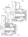
- a kneading trough 1 belonging to a kneading machine has sealing chambers 3 on both sides of its housing 2, in which there are shaft seals 4 and bearings 5 for mounting shaft journals 7 connected to a kneading tool 6.
- the shaft seals 4 are designed as non-contact seals with a return screw 8.
- the return screw 8 is in each case in a tube extension or pipe socket 9 forming a shaft passage, which is connected to the housing 2.
- the pipe lugs 9, which are coaxial with the shaft journals 7, have an inside diameter which is slightly larger than the outside diameter of the return screws 8. This results in contactless seals in which heating by friction practically does not occur.
- the intermediate gap 10 is dimensioned such that a good seal is provided when the return screw and the tube extension 9 are arranged in a contactless manner at the same time.
- the two return screws 8 belonging to a kneading tool 6 have opposite slopes with the inside of the kneading trough 1 and thus conveying directions directed towards one another. With the intended working direction of rotation of the kneading tool 6, the kneading product that gets into the area of the seals is thus pushed back by the return screws 8 to the inside of the kneading trough.
- the sealing chamber (s) 3 can, as shown in FIG. 2, be connected to the interior of the kneading trough 1 by means of a line 11.
- this line 11 serves as a pressure compensation line when kneading under vacuum.
- the sealing chamber 3 is simultaneously evacuated via the line 11 when the kneading trough 1 is evacuated.
- This has the advantage that the evacuation of the sealing chamber 3 does not have to take place via the sealing area in the shaft seal 4.
- the evacuation of the sealing chamber 3 would only be able to be carried out slowly and in an uncontrolled manner, in particular even if the return screw 8 was partially added with kneaded product. This is avoided by the pressure compensation line 11.
- the vacuum-tight chamber 3 on the side of the shaft journal 7 has a hermetically sealed cover 3a outside the bearing 5, so that the pressure-tight design of the chamber 3 is particularly simple here.
- the vacuum-tight chamber 3 On the side of the drive shaft 7 of the tool 6, the vacuum-tight chamber 3 is penetrated by this shaft 7 and has a seal 3b which acts on the continuous shaft 7 outside the shaft bearing 5.
- a seal 3b which acts on the continuous shaft 7 outside the shaft bearing 5.
- the seal 3b is also arranged in a cover 3c, which, however, has the passage for the shaft 7 and for receiving the seal 3b in the axial vicinity of the bearing 5.
- the 3 shows a metering device 12, by means of which additives can be fed via the return screw 8 to the kneading material located in the kneading trough.
- the metering device 12 has a storage container 13 which is connected to the return screw 8 via a metering tube 14.
- a valve 15 is also inserted in the course of the metering tube 14.
- the metering tube 14 opens approximately in the middle of the longitudinal extent of the return screw 8 and is connected when the tube extension 9 is opened.
- a total of four metering tubes can be connected.
- several metering tubes can optionally be connected per screw.
- the addition of additives in the area of the return screw 8 has the essential advantage that the dosing can be carried out more precisely and faster than when the additives are supplied through the housing cover, the additives having to be dusted or instilled there.
- the line 14 opening into the pipe socket 9 at its top and penetrating it is branched, and the respective branch 14a opens above a thread of the return screw conveyor 8. This not only refines and improves the metering, but above all the supply of cleaning agents and their effectiveness in the threads of the return screw 8 is improved.
- the storage container 13 is provided with a discharge cover 16, to which a relief valve 17 is connected.
- the addition of additives can be supported by opening the relief valve 17 by the external atmospheric pressure.
- the additives can be liquid or free-flowing product components.
- a cleaning agent e.g. a rinsing liquid can be supplied.
- the pipe lugs 9 are expediently divided in the area of the return screws, so that problem-free disassembly is possible in this area.
- the return screws can have a single start, which results in simple manufacture.
- the return screws 8 can have multiple threads, in particular three threads, so that a good seal is obtained even at low speeds.
Landscapes
- Chemical & Material Sciences (AREA)
- Chemical Kinetics & Catalysis (AREA)
- Processing And Handling Of Plastics And Other Materials For Molding In General (AREA)
- Accessories For Mixers (AREA)
- Formation And Processing Of Food Products (AREA)
- Preparation Of Clay, And Manufacture Of Mixtures Containing Clay Or Cement (AREA)
- Mixers Of The Rotary Stirring Type (AREA)
Claims (15)
Priority Applications (1)
| Application Number | Priority Date | Filing Date | Title |
|---|---|---|---|
| AT85105404T ATE35629T1 (de) | 1984-08-21 | 1985-05-03 | Knetmaschine. |
Applications Claiming Priority (2)
| Application Number | Priority Date | Filing Date | Title |
|---|---|---|---|
| DE3430671 | 1984-08-21 | ||
| DE3430671 | 1984-08-21 |
Publications (3)
| Publication Number | Publication Date |
|---|---|
| EP0172992A2 EP0172992A2 (fr) | 1986-03-05 |
| EP0172992A3 EP0172992A3 (en) | 1986-10-15 |
| EP0172992B1 true EP0172992B1 (fr) | 1988-07-13 |
Family
ID=6243515
Family Applications (1)
| Application Number | Title | Priority Date | Filing Date |
|---|---|---|---|
| EP85105404A Expired EP0172992B1 (fr) | 1984-08-21 | 1985-05-03 | Machine à pétrir |
Country Status (3)
| Country | Link |
|---|---|
| EP (1) | EP0172992B1 (fr) |
| AT (1) | ATE35629T1 (fr) |
| DE (1) | DE3563690D1 (fr) |
Family Cites Families (8)
| Publication number | Priority date | Publication date | Assignee | Title |
|---|---|---|---|---|
| US1673085A (en) * | 1926-08-04 | 1928-06-12 | Evarts G Loomis | Vacuum mixing machine |
| GB324763A (en) * | 1928-12-11 | 1930-02-06 | Charles William Bryant | Improvements in and relating to packings for shafts and the like |
| DE1080486B (de) * | 1958-11-12 | 1960-04-21 | Knapsack Ag | Staubdichte Durchfuehrung einer sich drehenden Hohlwelle durch einen Behaelterboden |
| FR74835E (fr) * | 1959-01-19 | 1961-03-03 | Alsacienne Constr Meca | Dispositif d'étanchéité entre un arbre et une paroi traversée par cet arbre |
| US3318606A (en) * | 1964-08-24 | 1967-05-09 | Read Corp | Agitator shaft seal for mixers |
| US3700247A (en) * | 1971-08-16 | 1972-10-24 | May V Latinen | Flush cooling of shaft sealing screw means |
| US4091520A (en) * | 1972-06-09 | 1978-05-30 | Stichting Reactor Centrum Nederland | Process for making a gastight passage |
| US4300842A (en) * | 1978-12-01 | 1981-11-17 | Usm Corporation | Seals for rotary processor |
-
1985
- 1985-05-03 AT AT85105404T patent/ATE35629T1/de not_active IP Right Cessation
- 1985-05-03 EP EP85105404A patent/EP0172992B1/fr not_active Expired
- 1985-05-03 DE DE8585105404T patent/DE3563690D1/de not_active Expired
Also Published As
| Publication number | Publication date |
|---|---|
| EP0172992A2 (fr) | 1986-03-05 |
| DE3563690D1 (en) | 1988-08-18 |
| ATE35629T1 (de) | 1988-07-15 |
| EP0172992A3 (en) | 1986-10-15 |
Similar Documents
| Publication | Publication Date | Title |
|---|---|---|
| EP1287878B1 (fr) | Appareil de traitement des materiaux | |
| DE1806638A1 (de) | Kontinuierlich arbeitende Misch- und Knetmaschine | |
| DE3344531C2 (de) | Mischvorrichtung | |
| DE3520662A1 (de) | Wellendichtung fuer eine vorrichtung zur kontinuierlichen verarbeitung hochviskoser medien, insbesondere zur herstellung hochmolekularer polymere | |
| CH655229A5 (de) | Vorrichtung zum kontinuierlichen kochen unter druck, extrudieren und ausformen von lebensmittel-formkoerpern. | |
| EP0509218B1 (fr) | Pompe à engrenages | |
| EP0125389B1 (fr) | Dispositif de préparation de fluides | |
| DE29580146U1 (de) | Zuteilerrohr | |
| EP0098340B1 (fr) | Pompe à hélice dont l'arbre est supporté à ses deux extrémités | |
| DE2905665C2 (de) | Schneckenförderer | |
| EP0012795B1 (fr) | Boudineuse à vis pour le travail de matières plastiques, de caoutchouc ou analogues | |
| DE3341857A1 (de) | Kegelbrecher | |
| DE102010018420B4 (de) | Walzenpresse | |
| DE2415593C2 (de) | Silo zum Speichern von schüttfähigem, jedoch schwerfließendem Gut | |
| EP0761295A1 (fr) | Mélangeur-pétrisseur | |
| DE29921445U1 (de) | Schlaufenreaktor | |
| DE1299094B (de) | Vorrichtung zum Einfuehren von zerkleinertem Feststoffmaterial, insbesondere von feuchter feinkoerniger Kohle, in einen zum Transport des Feststoffmaterials dienenden Druckgasstrom | |
| DE2321492A1 (de) | Vorrichtung zum mischen und foerdern von staub- oder granulatfoermigem gut mit wasser | |
| DE29610612U1 (de) | Rotationsventil mit einer großen Dichtigkeit | |
| EP0172992A2 (fr) | Machine à pétrir | |
| DE1461012B2 (de) | Vorrichtung zum zerfasern von papierstoff | |
| DE8513013U1 (de) | Knetmaschine | |
| CH232413A (de) | Walzwerk für plastische körnige Massen. | |
| DE3406648A1 (de) | Mischmaschine fuer kontinuierliche mischverfahren | |
| DE1203180B (de) | Foerdervorrichtung zum Zufuehren von grob- oder feinkoernigem Material aus einem Behaelter in eine pneumatische Foerderleitung |
Legal Events
| Date | Code | Title | Description |
|---|---|---|---|
| PUAI | Public reference made under article 153(3) epc to a published international application that has entered the european phase |
Free format text: ORIGINAL CODE: 0009012 |
|
| AK | Designated contracting states |
Kind code of ref document: A2 Designated state(s): AT BE CH DE FR GB IT LI LU NL SE |
|
| PUAL | Search report despatched |
Free format text: ORIGINAL CODE: 0009013 |
|
| AK | Designated contracting states |
Kind code of ref document: A3 Designated state(s): AT BE CH DE FR GB IT LI LU NL SE |
|
| 17P | Request for examination filed |
Effective date: 19860926 |
|
| RAP1 | Party data changed (applicant data changed or rights of an application transferred) |
Owner name: IKA-MASCHINENBAU JANKE & KUNKEL GMBH & CO. KG |
|
| 17Q | First examination report despatched |
Effective date: 19871030 |
|
| ITF | It: translation for a ep patent filed | ||
| GRAA | (expected) grant |
Free format text: ORIGINAL CODE: 0009210 |
|
| AK | Designated contracting states |
Kind code of ref document: B1 Designated state(s): AT BE CH DE FR GB IT LI LU NL SE |
|
| PG25 | Lapsed in a contracting state [announced via postgrant information from national office to epo] |
Ref country code: SE Effective date: 19880713 Ref country code: NL Effective date: 19880713 |
|
| REF | Corresponds to: |
Ref document number: 35629 Country of ref document: AT Date of ref document: 19880715 Kind code of ref document: T |
|
| REF | Corresponds to: |
Ref document number: 3563690 Country of ref document: DE Date of ref document: 19880818 |
|
| ET | Fr: translation filed | ||
| GBT | Gb: translation of ep patent filed (gb section 77(6)(a)/1977) | ||
| NLV1 | Nl: lapsed or annulled due to failure to fulfill the requirements of art. 29p and 29m of the patents act | ||
| PLBE | No opposition filed within time limit |
Free format text: ORIGINAL CODE: 0009261 |
|
| STAA | Information on the status of an ep patent application or granted ep patent |
Free format text: STATUS: NO OPPOSITION FILED WITHIN TIME LIMIT |
|
| 26N | No opposition filed | ||
| PGFP | Annual fee paid to national office [announced via postgrant information from national office to epo] |
Ref country code: GB Payment date: 19910426 Year of fee payment: 7 |
|
| PGFP | Annual fee paid to national office [announced via postgrant information from national office to epo] |
Ref country code: FR Payment date: 19910429 Year of fee payment: 7 |
|
| PGFP | Annual fee paid to national office [announced via postgrant information from national office to epo] |
Ref country code: CH Payment date: 19910513 Year of fee payment: 7 |
|
| PGFP | Annual fee paid to national office [announced via postgrant information from national office to epo] |
Ref country code: LU Payment date: 19910523 Year of fee payment: 7 |
|
| PGFP | Annual fee paid to national office [announced via postgrant information from national office to epo] |
Ref country code: DE Payment date: 19910524 Year of fee payment: 7 |
|
| ITTA | It: last paid annual fee | ||
| PGFP | Annual fee paid to national office [announced via postgrant information from national office to epo] |
Ref country code: AT Payment date: 19910531 Year of fee payment: 7 |
|
| PGFP | Annual fee paid to national office [announced via postgrant information from national office to epo] |
Ref country code: BE Payment date: 19910715 Year of fee payment: 7 |
|
| EPTA | Lu: last paid annual fee | ||
| PG25 | Lapsed in a contracting state [announced via postgrant information from national office to epo] |
Ref country code: LU Free format text: LAPSE BECAUSE OF NON-PAYMENT OF DUE FEES Effective date: 19920503 Ref country code: GB Effective date: 19920503 Ref country code: AT Effective date: 19920503 |
|
| PG25 | Lapsed in a contracting state [announced via postgrant information from national office to epo] |
Ref country code: LI Effective date: 19920531 Ref country code: CH Effective date: 19920531 Ref country code: BE Effective date: 19920531 |
|
| BERE | Be: lapsed |
Owner name: IKA-MASCHINENBAU JANKE & KUNKEL G.M.B.H. & CO. K. Effective date: 19920531 |
|
| GBPC | Gb: european patent ceased through non-payment of renewal fee |
Effective date: 19920503 |
|
| PG25 | Lapsed in a contracting state [announced via postgrant information from national office to epo] |
Ref country code: FR Effective date: 19930129 |
|
| REG | Reference to a national code |
Ref country code: CH Ref legal event code: PL |
|
| PG25 | Lapsed in a contracting state [announced via postgrant information from national office to epo] |
Ref country code: DE Effective date: 19930202 |
|
| REG | Reference to a national code |
Ref country code: FR Ref legal event code: ST |