EP0173364B1 - Method, station and system for the transmission of messages in the form of data packets - Google Patents
Method, station and system for the transmission of messages in the form of data packets Download PDFInfo
- Publication number
- EP0173364B1 EP0173364B1 EP85201157A EP85201157A EP0173364B1 EP 0173364 B1 EP0173364 B1 EP 0173364B1 EP 85201157 A EP85201157 A EP 85201157A EP 85201157 A EP85201157 A EP 85201157A EP 0173364 B1 EP0173364 B1 EP 0173364B1
- Authority
- EP
- European Patent Office
- Prior art keywords
- station
- frame
- data packets
- transmission
- message
- Prior art date
- Legal status (The legal status is an assumption and is not a legal conclusion. Google has not performed a legal analysis and makes no representation as to the accuracy of the status listed.)
- Expired
Links
Images


Classifications
-
- H—ELECTRICITY
- H04—ELECTRIC COMMUNICATION TECHNIQUE
- H04L—TRANSMISSION OF DIGITAL INFORMATION, e.g. TELEGRAPHIC COMMUNICATION
- H04L12/00—Data switching networks
- H04L12/28—Data switching networks characterised by path configuration, e.g. LAN [Local Area Networks] or WAN [Wide Area Networks]
- H04L12/40—Bus networks
- H04L12/403—Bus networks with centralised control, e.g. polling
- H04L12/4035—Bus networks with centralised control, e.g. polling in which slots of a TDMA packet structure are assigned based on a contention resolution carried out at a master unit
-
- H—ELECTRICITY
- H04—ELECTRIC COMMUNICATION TECHNIQUE
- H04L—TRANSMISSION OF DIGITAL INFORMATION, e.g. TELEGRAPHIC COMMUNICATION
- H04L12/00—Data switching networks
- H04L12/28—Data switching networks characterised by path configuration, e.g. LAN [Local Area Networks] or WAN [Wide Area Networks]
- H04L12/40—Bus networks
- H04L12/407—Bus networks with decentralised control
- H04L12/413—Bus networks with decentralised control with random access, e.g. carrier-sense multiple-access with collision detection [CSMA-CD]
-
- H—ELECTRICITY
- H04—ELECTRIC COMMUNICATION TECHNIQUE
- H04M—TELEPHONIC COMMUNICATION
- H04M9/00—Arrangements for interconnection not involving centralised switching
- H04M9/02—Arrangements for interconnection not involving centralised switching involving a common line for all parties
- H04M9/022—Multiplex systems
- H04M9/025—Time division multiplex systems, e.g. loop systems
Definitions
- the invention relates to a method of transmitting messages formed by data packets between stations via a common communication channel formed by corresponding time slots in consecutive frames of a time-division multiplex system,
- the invention also relates to a station for performing that method and a system of stations having a common communication channel.
- the manner described there for the stations to access the communication channel is known as the CSAMA-CD protocol (Carrier Sense Multiple Access with Collision Detection). If in such a system several stations start transmitting data packets simultaneously a collision state occurs which is detected by the transmitting stations in that they detect in equality beween the data transmitted by them and the data simultaneously present in the communication channels. Repeated transmission of the data packets must then occur in accordance with a retransmission procedure so as to accomplish undisturbed transmission as yet.
- CSAMA-CD protocol Carrier Sense Multiple Access with Collision Detection
- the retransmission procedure adopted in the system in accordance with the above-mentioned United States Patent consists in that after collision a data packet must wait for a waiting time which is directly ascertained after the collision before transmission can be resumed.
- the waiting times in the stations of this system are statistically distributed, the waiting time being influenced by a weighting factor which depends on the number of times collision has occurred on transmission of a data packet.
- the invention has for its object to provide a method of the type described in the opening paragraph with which access of collided data packets to the communication channel is guaranteed.
- the method is therefore characterized in that
- An alternative possibility is to limit the number of frames which are to be counted down after collision.
- An embodiment of the method in which this feature is used, is therefore characterized in that,
- a method which, before proceeding to retransmission of one type of messages first enables the transmission of non-collided messages of a different type, is therefore characterized in that
- Providing the flag may prevent non-collided messages of a first type from repeatedly preceding the retransmission of messages of the same type. It also prevents messages of the second type waiting for retransmission from interfering with retransmission of messages of the first type.
- Figure 1 shows a system of a number of stations 11-1 to 11-N connected to a common bus 12.
- stations may be telecommunications terminals such as, for example, telephone sets or telex apparatus. They may alternatively be data-processing apparatus such as, for example, word processors or personal computers.
- Sensor stations for safety purposes or for process control, such as for example fire sensors or temperature sensors for room heating can also function as stations in this system.
- Each of these stations has an address number which unambiguously identifies this station within the system. This address number is important for the selection, still to be described in the sequel, of a main station for synchronizing purposes and for the retransmission, also to be further described in the sequel, of message which were mutilated during transmission.
- Bus 12 is a two-wire conductor whose ends are terminated by terminating impedances 13-1 and 13-2.
- a direct current supply source 14 can be connected to bus 12 for feeding the stations.
- the signal transmission via the bus is effected in binary encoded form.
- One of these two binary values (for example "0") can be represented by the electrically floating state of the bus whilst the other binary value (“1") is represented by a voltage difference.
- the advantage thereof is that if two stations transmit simultaneously, the "0" of one station is suppressed by the "1" of the other station, which facilitates detection of this collision situation by the station transmitting the "0".
- Communication in such a system requires the time-division multiplex frames in all the connected stations to be mutually synchronized. This synchronization is obtained by means of a synchronizing signal transmitted in a synchronizing channel intended therefor by one of the stations, the main station.
- This procedure consists in that in each station one unit is each time added to the address number until a predetermined final value has been reached in one station, which then becomes the main station. Should that station be removed from the bus, then this selection procedure is performed again until a new main station has been selected.
- the station is not only connectable to the bus but also to an external communication channel, (for example a private or public telephone network), that external communication channel also being formed by a sequence of time slots. It is then necessary to synchronize the bus with the external communication channels.
- an external communication channel for example a private or public telephone network
- the stations having an external connecting feature must be given priority during the selection procedure of the main station, these stations comprise an additional "address bit", so that these stations always have a higher address number than the other stations.
- the upper diagram shows the frame structure of the time-division multiplex system.
- the frame repetition rate is adapted to the standard 8 kHz sampling rate for digital speech transmission, so that a frame period of 125 ⁇ s is obtained.
- the frame is divided into ten channels, namely one synchronizing channel R, one half-duplex channel (bd) for system control (signalling) and for message-switched data transmission and eight half-duplex channels b 1 to b 8 for circuit-switched speech and data transmission.
- a maximum of, for example, four telephone conversations are simultaneously possible in this frame structure.
- the F-channel for synchronization contains a five-bit word.
- the remaining channels may contain a nine-bit word and leave 4 bit positions unoccupied to offset the delay caused by the required propagation time in the bus conductor. Together with the spaces between the channels in the above-mentioned bit occupation of the channels produces a bit rate on the bus of the order of magnitude of 1 Mbit/s.
- each frame of such a busy channel starts with a "1", referred to as the start bit.
- This start bit is followed in the same frame by a bit word of four (F-channel) or eight bits (remaining channels).
- Each station is now capable of detecting the traffic state (free or busy) of a channel by observing the first bit position in each frame of that channel.
- Access of a station to a circuit-switched channel must be realized via preceding signalling in the bd-channel.
- the channel starts by transmitting a message in the bd-channel when this channel is free.
- This message is formed by a message identification, the address number of that station and two check words, referred to as CRC-bytes (Cyclic Redundancy Check). Since the address number is unique for each station, the transmitting station can ascertain whether another station has simultaneously started the transmission of a similar message. If yes, collision is unavoidable, as all the address numbers are mutually different. Upon an undisturbed transmission of the address number it is certain that no other station has had access to the bd channel.
- the station which was the sole station transmitting via the bd-channel now consequently is also the sole station accessing one of the channels b 1 -b s , provided one of these channels is free. Acting thus prevents collision in a circuit-switched channel. Consequently, collisions can only occur on transmission via the bd-channel.
- the invention provides a method which is suitable for solving collision problems in such a way that it is ensured that messages involved in a collision can be transmitted without mutilations after this collision. This method is illustrated in the lower diagram of Figure 2.
- the lower diagram of Figure 2 shows a sequence of frames of the bd-channel.
- the top row of this diagram illustrates the traffic state, Empty (E) or Busy (B).
- a dash (-) indicates that such a frame can be both empty and busy.
- the central row of this diagram shows the name of the several frames.
- B is a frame being used for the transmission of a byte.
- E is a frame which is always kept empty.
- the messages in the bd-channel can be distinguished in two types by their function in the system.
- a first type includes, for example, the messages which form the signalling for the setting-up of a circuit-switched connection between two stations.
- the messages providing the system control belong to this first category.
- the length of these messages is limited, whilst for their function (system control) a fast transmission is desirable.
- the second category is formed by messages embodying, for example, the data for telemetry or (slow) data transmission between computers. They may be comparatively long messages having a comparatively low urgency.
- the first category is referred to as an s-message, the second category as a d-message.
- S and D are frames intended for starting the transmission of s-messages and d-messages, respectively.
- the frames H 00 to L 111 are intended for starting the re-transmission of messages involved in a collision or which were received mutilated.
- the lower row of the diagram of Figure 2 illustrates the numbering of the several frames.
- the frame counter FC is in the zero position.
- an empty frame always occurs, which causes the frame counter to increment to 1.1 (in this empty frame receiving stations can carry out their error check CRC). If a station has detected an error then this station transmits a NACK signal in frame 2, which causes the transmitting station to effect a re-transmission in one of the frames 9 to 16. If during frame 1 no error is detected then frame 2 remains empty.
- the empty frame 3 is only included because of the lack of computation time and has no further significance for the invention.
- Frame 4 in Figure 2 is intended for the start of new s-messages.
- This new s-message consequently has priority over retransmission of both d- and s-messages.
- This realizes the precedence of s-messages over d-messages during retransmission of d-messages.
- a flag is placed which prevents, after the end of that new s-message, a further new s-message from postponing the retransmission of s-messages again.
- the frames 9 to 16 are intended for first retransmissions, the frames 5 to 8 for further retransmissions. In frames 17 and 18 s-messages and d-messages, respectively can start again.
- the frame counter changes-over between counting positions 17 and 18.
- a station having a message for transmission via the bd-channel takes access to that channel, the frame counter then being adjusted to zero. After the end of the message the frame counter starts counting from zero. If in frame 2 no NACK byte is received, then the frame counter proceeds to 17 and 18, whereafter the counter starts alternating between 17 and 18 ("toggling"). If a NACK byte was indeed received in frame 2 then the station starts retransmission in that L-frame which corresponds to its address number. After that retransmission has ended the frame counter again passes from 0 to 18 and starts toggling.
- each of the stations detects that its message is mutilated.
- the stations now stop the transmission of the message and in the next frame send a disturb signal (formed by the NACK-byte consisting of 9 "1"-bits), whereafter the subsequent frame is again kept empty.
- the counter goes to 1
- the other stations detect in frame 1 an error on the basis of their error check and transmit a NACK-byte in frame 2.
- retransmission in the event of collision in an L-frame
- a second retransmission in a H-frame collision being impossible.
- the transmitting station again receives a NACK-byte in frame 2, namely when the message is mutilated on transmission or when the receiving station is not capable of accepting the message. To distinguish between these two situations a third retransmission is affected, also in the corresponding H-frame. If thereafter a NACK byte is received again, then the transmitting station decides that the receiving station is not capable of accepting the message and terminates further transmission. After the last-NACK-type (counting position 2) the frame counters in the stations pass once again through the positions up to 18, inclusive and start toggling thereafter.
- the frame counter returns from position 16 to position 3 and thereafter starts to count up whilst at the same time the flag is adjusted to the non-set state.
- the object thereof is to offer the d-message (which could not be transmitted in an earlier stage because the flag was in the set state) the opportunity to be transmitted. After the frame counter has returned to position 3 it is still possible that in the subsequent frame 4 an s-message starts again, the flag being set.
- Figure 3 shows a block circuit diagram of a station 3-10 in accordance with the invention, connected to the bus 12.
- the station comprises a receiver 3-11 which takes signals from the bus and a transmitter 3-12 transmitting signals to the bus.
- a channel comparator 3-13 is provided, which is connected to the transmitter input and to the receiver output.
- An alarm signal detector 3-14 is also provided for detecting alarm signals (NACK-bytes) in the communication channel.
- the outputs of channel comparator 3-13 and alarm signal detector 3-14 are connected to an OR-gate 3-15, whose output is connected to a counting unit 3-16.
- This counting unit is constituted by two retransmission counters, one for s-messages 3-17, and one for d-messages 3-18. Both counters are connected to the central control 3-19 of the station for activation by a s-message and a d-message, respectively.
- the station further comprises a using unit 3-20 for converting the received information into a form suitable for use.
- a unit may, for example, be in the form of a picture screen, a printer or a circuit of a telephone set.
- Using unit 3-20 transfers the bytes to be transmitted to buffer store 3-21 from which these bytes are transmitted to the bus by transmitter 3-12.
- energizing means 3-22 are connected to transmitter 3-12, which energize transmitter 3-12 for transmitting the content of buffer store 3-21 in dependence on the position of the frame counter, of the station address number, the type of message (s or d), whether the flag is in the set or the non-set state (when frame 4 is occupied) and on the position of the retransmission counter.
- the energizing means 3-22 receive information from counter comparator 3-23 which compares the content of address store 3-24 to the content of frame counter 3-25. This comparison is necessary for selecting the appropriate frame for retransmission; the energizing means receive further information necessary for this selection from the central control 3-19.
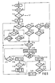
- the flow chart of Figure 1 illustrates how the various counting positions of the frame counter are obtained. In all stations the counting position of the frame counters are equal to each other. The portion of the flow chart located below block 4-2 is passed through once in each frame. The several blocks in the flow chart have the following significance:
- the non-set state of the flag (indicating the start of an s-message in frame 4) is set, whereafter the then subsequent cycle is repeated in each frame.
- the frame counter is kept at zero.
- the frame counter can continue counting after frame synchronization. In counting position 4 an s-message may be transmitted over the bus; if no message is transmitted then the frame counter counts on to alternately position 17/18 in which an s-message may alternately start.
- the channel being occupied and the frame counter being in counting position 2 inevitably denotes a NACK-signal; the frame counter now continues to count via block 4-12. In that case, if no new s-message is started in frame 4, the retransmission field 5 to 16 is cycled through. In one of these frame the collided or mutilated message can be retransmitted.
- the channel being occupied and the frame counter being in position 4 is a sure indication of a new s-message in frame 4; now the flag is set, block 4-8. In all other cases the channel is normally occupied, the frame counter always being kept at 0, block 4-9.
- any deviations of a frame counter of a given station is corrected automatically without outside action.
- Such deviations can, for example, occur because the station is connected to the bus at a later instant than the other stations, has been removed from the bus for some time of by externally induced interferences.
- the frame counter of that station is indeed originally not in synchronism with the other frame counters, (thus this frame counter shows other frame numbers) but at the first occupied frames detected by that station the frame counter will be adjusted to the zero position or the station will cause collision.
- synchronization is obtained
- a retransmission procedure is started, also beginning with frame counter position 0, which also accomplishes synchronization.
- the adopted method renders the frame counting and consequently the access procedure self-repairing.
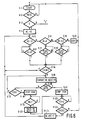
- the flow chart of Figure 5 illustrates the course of the access procedure for the bd channel of an s-message to be transmitted by a station.
- the blocks in this flow chart have the following significance:
- the message to be transmitted is an s-message. If no, then the access-procedure for d-messages is proceeded too, which is symbolically shown in Figure 5 in block 5-3 by "d"; the d-procedure is then started at the input of block 6-4, Figure 6. If yes, then the message is transmitted, the path 5-4, 5-5, 5-6, 5-7, 5-14, 5-15, 5-16, 5-17,..., 5-15, 5-16, 5-21, 5-22, 5-23, 5-1 being followed further.
- the path is followed via the block 5-16, 5-17 to 5-20, 5-22, 5-23, 5-24 and back to 5-5.
- the path is now chosen which leads from 5-5 via the blocks 5-9, 5-11, 5-14, 5-15, 5-16, 5-17. Let it be assumed that during this first retransmission collision occurs again, so that the path is continued via the blocks 5-18, 5-19, 5-20, 5-22, 5-23, 5-24, and back again to 5-5.
- the path is taken from block 5-5 via the blocks 5-9, 5-10, 5-12, 5-14, 5-15, 5-16, 5-17.
- the flow chart of Figure 6 shows the course of the access procedure to the bd-channel of a d-message to be transmitted by a station.
- the blocks in this flow chart have the following significance:
Landscapes
- Engineering & Computer Science (AREA)
- Signal Processing (AREA)
- Computer Networks & Wireless Communication (AREA)
- Small-Scale Networks (AREA)
- Communication Control (AREA)
- Data Exchanges In Wide-Area Networks (AREA)
- Radar Systems Or Details Thereof (AREA)
- Meter Arrangements (AREA)
- Mobile Radio Communication Systems (AREA)
Priority Applications (1)
| Application Number | Priority Date | Filing Date | Title |
|---|---|---|---|
| AT85201157T ATE48212T1 (de) | 1984-07-27 | 1985-07-10 | Verfahren, station und system zur uebertragung von nachrichten in form von datenpaketen. |
Applications Claiming Priority (2)
| Application Number | Priority Date | Filing Date | Title |
|---|---|---|---|
| NL8402364 | 1984-07-27 | ||
| NL8402364A NL8402364A (nl) | 1984-07-27 | 1984-07-27 | Werkwijze, station en systeem voor de overdracht van uit datapakketten bestaande berichten. |
Publications (2)
| Publication Number | Publication Date |
|---|---|
| EP0173364A1 EP0173364A1 (en) | 1986-03-05 |
| EP0173364B1 true EP0173364B1 (en) | 1989-11-23 |
Family
ID=19844278
Family Applications (1)
| Application Number | Title | Priority Date | Filing Date |
|---|---|---|---|
| EP85201157A Expired EP0173364B1 (en) | 1984-07-27 | 1985-07-10 | Method, station and system for the transmission of messages in the form of data packets |
Country Status (12)
| Country | Link |
|---|---|
| US (1) | US4672606A (da) |
| EP (1) | EP0173364B1 (da) |
| JP (1) | JPH0683210B2 (da) |
| AT (1) | ATE48212T1 (da) |
| AU (1) | AU578393B2 (da) |
| CA (1) | CA1257020A (da) |
| DE (1) | DE3574439D1 (da) |
| DK (1) | DK337585A (da) |
| HK (1) | HK87891A (da) |
| IL (1) | IL75905A (da) |
| NL (1) | NL8402364A (da) |
| SG (1) | SG88490G (da) |
Families Citing this family (12)
| Publication number | Priority date | Publication date | Assignee | Title |
|---|---|---|---|---|
| JPS6489737A (en) * | 1987-09-30 | 1989-04-04 | Toshiba Corp | Multiple address communication data transmission system |
| NL8800698A (nl) * | 1988-03-21 | 1989-10-16 | Philips Nv | Werkwijze voor het vanuit een besturingseenheid quasi parallel besturen van een aantal perifere eenheden en stelsel voor het uitvoeren van deze werkwijze. |
| US5487066A (en) * | 1988-03-21 | 1996-01-23 | First Pacific Networks, Inc. | Distributed intelligence network using time and frequency multiplexing |
| JPH04506729A (ja) * | 1989-04-28 | 1992-11-19 | ファースト パシフィック ネットワークス,インコーポレイテッド | 時間及び周波数多重化を使用した分散型インテリジェンスネットワーク |
| US5239540A (en) * | 1990-11-27 | 1993-08-24 | Scientific-Atlanta, Inc. | Method and apparatus for transmitting, receiving and communicating digital data signals with corresponding program data signals which describe the digital data signals |
| US5586150A (en) * | 1993-11-24 | 1996-12-17 | Rajupandaram K. Balasubramaniam | Method and apparatus for symbol synchronization in multi-level digital FM radio |
| AU4913797A (en) * | 1996-10-17 | 1998-05-11 | Ian R. Davison | System and method for internetworking devices |
| KR20050052484A (ko) * | 1997-03-17 | 2005-06-02 | 마츠시타 덴끼 산교 가부시키가이샤 | 데이터 처리방법 |
| US6266540B1 (en) * | 1998-11-30 | 2001-07-24 | Qualcomm Inc | Control interface protocol for telephone sets for a satellite telephone system |
| GB9908805D0 (en) * | 1999-04-16 | 1999-06-09 | Nokia Telecommunications Oy | A method of transmitting |
| US6888819B1 (en) * | 2000-10-04 | 2005-05-03 | Yitran Communications Ltd. | Media access control utilizing synchronization signaling |
| US9483209B2 (en) * | 2014-09-22 | 2016-11-01 | Freescale Semiconductor, Inc. | Interface system and method |
Family Cites Families (6)
| Publication number | Priority date | Publication date | Assignee | Title |
|---|---|---|---|---|
| SE430740B (sv) * | 1982-04-26 | 1983-12-05 | Ellemtel Utvecklings Ab | Anordning for synkronisering av overforing av information pa en enkelriktad buss |
| JPS592463A (ja) * | 1982-06-29 | 1984-01-09 | Fuji Xerox Co Ltd | 再送制御方式 |
| US4513370A (en) * | 1982-07-19 | 1985-04-23 | Amdahl Corporation | Data transfer control system and method for a plurality of linked stations |
| JPS5923654A (ja) * | 1982-07-29 | 1984-02-07 | Sharp Corp | デ−タ伝送装置 |
| GB2125257B (en) * | 1982-08-04 | 1986-03-26 | Plessey Co Plc | Improved local area network systems |
| JPS604347A (ja) * | 1983-06-22 | 1985-01-10 | Fuji Xerox Co Ltd | デイジタル信号伝送システムの障害対策方式 |
-
1984
- 1984-07-27 NL NL8402364A patent/NL8402364A/nl not_active Application Discontinuation
-
1985
- 1985-07-10 EP EP85201157A patent/EP0173364B1/en not_active Expired
- 1985-07-10 AT AT85201157T patent/ATE48212T1/de not_active IP Right Cessation
- 1985-07-10 DE DE8585201157T patent/DE3574439D1/de not_active Expired
- 1985-07-17 US US06/756,141 patent/US4672606A/en not_active Expired - Fee Related
- 1985-07-24 IL IL75905A patent/IL75905A/en not_active IP Right Cessation
- 1985-07-24 DK DK337585A patent/DK337585A/da not_active Application Discontinuation
- 1985-07-25 CA CA000487496A patent/CA1257020A/en not_active Expired
- 1985-07-25 JP JP60163065A patent/JPH0683210B2/ja not_active Expired - Lifetime
- 1985-07-26 AU AU45510/85A patent/AU578393B2/en not_active Ceased
-
1990
- 1990-10-25 SG SG884/90A patent/SG88490G/en unknown
-
1991
- 1991-11-07 HK HK878/91A patent/HK87891A/en not_active IP Right Cessation
Also Published As
| Publication number | Publication date |
|---|---|
| DE3574439D1 (en) | 1989-12-28 |
| DK337585D0 (da) | 1985-07-24 |
| US4672606A (en) | 1987-06-09 |
| AU578393B2 (en) | 1988-10-20 |
| DK337585A (da) | 1986-01-28 |
| JPS6141249A (ja) | 1986-02-27 |
| JPH0683210B2 (ja) | 1994-10-19 |
| ATE48212T1 (de) | 1989-12-15 |
| CA1257020A (en) | 1989-07-04 |
| AU4551085A (en) | 1986-01-30 |
| IL75905A0 (en) | 1985-12-31 |
| NL8402364A (nl) | 1986-02-17 |
| HK87891A (en) | 1991-11-15 |
| EP0173364A1 (en) | 1986-03-05 |
| IL75905A (en) | 1989-07-31 |
| SG88490G (en) | 1990-12-21 |
Similar Documents
| Publication | Publication Date | Title |
|---|---|---|
| EP0117677B1 (en) | Data communication systems | |
| JP2979319B2 (ja) | 無線デイジタル電話システム用基地局 | |
| EP0173364B1 (en) | Method, station and system for the transmission of messages in the form of data packets | |
| EP0100662B1 (en) | Digital communication system | |
| US4507778A (en) | Digital transmission system | |
| US4337465A (en) | Line driver circuit for a local area contention network | |
| US5960001A (en) | Apparatus and method for guaranteeing isochronous data flow on a CSMA/CD network | |
| US4470110A (en) | System for distributed priority arbitration among several processing units competing for access to a common data channel | |
| EP0060517A1 (en) | Multiple access system of terminals on a digital telephone line | |
| EP0539796A2 (en) | Method for data collision detection in a multi-processor communication system | |
| JPH0354907B2 (da) | ||
| FR2543767A1 (fr) | Dispositif d'echange de messages codes entre stations | |
| US3890460A (en) | Communications enabling method and apparatus | |
| JPS6218154A (ja) | 通信システムのメツセ−ジチヤネルのアクセスおよび利用方法とその装置 | |
| US4538261A (en) | Channel access system | |
| EP0077913B1 (en) | Signalling communication apparatus | |
| US4677613A (en) | Network system for connecting multiple I/O devices to computers | |
| JPH0457140B2 (da) | ||
| JPS62206942A (ja) | デ−タ伝送方式 | |
| JP3042822B2 (ja) | バス競合制御方式 | |
| US5751974A (en) | Contention resolution for a shared access bus | |
| JPS6165552A (ja) | 通信方式 | |
| JPS5951794B2 (ja) | 分散型電子交換機の制御方式 | |
| JP3199431B2 (ja) | 通信制御装置および通信制御方法 | |
| JPS6366462B2 (da) |
Legal Events
| Date | Code | Title | Description |
|---|---|---|---|
| PUAI | Public reference made under article 153(3) epc to a published international application that has entered the european phase |
Free format text: ORIGINAL CODE: 0009012 |
|
| AK | Designated contracting states |
Kind code of ref document: A1 Designated state(s): AT BE CH DE FR GB IT LI SE |
|
| 17P | Request for examination filed |
Effective date: 19860829 |
|
| 17Q | First examination report despatched |
Effective date: 19880822 |
|
| GRAA | (expected) grant |
Free format text: ORIGINAL CODE: 0009210 |
|
| AK | Designated contracting states |
Kind code of ref document: B1 Designated state(s): AT BE CH DE FR GB IT LI SE |
|
| REF | Corresponds to: |
Ref document number: 48212 Country of ref document: AT Date of ref document: 19891215 Kind code of ref document: T |
|
| REF | Corresponds to: |
Ref document number: 3574439 Country of ref document: DE Date of ref document: 19891228 |
|
| ITF | It: translation for a ep patent filed | ||
| ET | Fr: translation filed | ||
| PGFP | Annual fee paid to national office [announced via postgrant information from national office to epo] |
Ref country code: BE Payment date: 19900705 Year of fee payment: 6 |
|
| PLBE | No opposition filed within time limit |
Free format text: ORIGINAL CODE: 0009261 |
|
| STAA | Information on the status of an ep patent application or granted ep patent |
Free format text: STATUS: NO OPPOSITION FILED WITHIN TIME LIMIT |
|
| 26N | No opposition filed | ||
| PG25 | Lapsed in a contracting state [announced via postgrant information from national office to epo] |
Ref country code: BE Effective date: 19910731 |
|
| BERE | Be: lapsed |
Owner name: PHILIPS' GLOEILAMPENFABRIEKEN N.V. Effective date: 19910731 |
|
| PGFP | Annual fee paid to national office [announced via postgrant information from national office to epo] |
Ref country code: AT Payment date: 19920724 Year of fee payment: 8 |
|
| PG25 | Lapsed in a contracting state [announced via postgrant information from national office to epo] |
Ref country code: AT Effective date: 19930710 |
|
| ITTA | It: last paid annual fee | ||
| EAL | Se: european patent in force in sweden |
Ref document number: 85201157.6 |
|
| ITPR | It: changes in ownership of a european patent |
Owner name: CAMBIO RAGIONE SOCIALE;PHILIPS ELECTRONICS N.V. |
|
| REG | Reference to a national code |
Ref country code: CH Ref legal event code: PFA Free format text: PHILIPS ELECTRONICS N.V. |
|
| REG | Reference to a national code |
Ref country code: FR Ref legal event code: CD |
|
| PGFP | Annual fee paid to national office [announced via postgrant information from national office to epo] |
Ref country code: SE Payment date: 19950726 Year of fee payment: 11 |
|
| PGFP | Annual fee paid to national office [announced via postgrant information from national office to epo] |
Ref country code: CH Payment date: 19951024 Year of fee payment: 11 |
|
| PGFP | Annual fee paid to national office [announced via postgrant information from national office to epo] |
Ref country code: GB Payment date: 19960701 Year of fee payment: 12 |
|
| PG25 | Lapsed in a contracting state [announced via postgrant information from national office to epo] |
Ref country code: SE Effective date: 19960711 |
|
| PGFP | Annual fee paid to national office [announced via postgrant information from national office to epo] |
Ref country code: FR Payment date: 19960724 Year of fee payment: 12 |
|
| PG25 | Lapsed in a contracting state [announced via postgrant information from national office to epo] |
Ref country code: LI Effective date: 19960731 Ref country code: CH Effective date: 19960731 |
|
| PGFP | Annual fee paid to national office [announced via postgrant information from national office to epo] |
Ref country code: DE Payment date: 19960924 Year of fee payment: 12 |
|
| REG | Reference to a national code |
Ref country code: CH Ref legal event code: PL |
|
| EUG | Se: european patent has lapsed |
Ref document number: 85201157.6 |
|
| PG25 | Lapsed in a contracting state [announced via postgrant information from national office to epo] |
Ref country code: GB Free format text: LAPSE BECAUSE OF NON-PAYMENT OF DUE FEES Effective date: 19970710 |
|
| GBPC | Gb: european patent ceased through non-payment of renewal fee |
Effective date: 19970710 |
|
| PG25 | Lapsed in a contracting state [announced via postgrant information from national office to epo] |
Ref country code: FR Free format text: LAPSE BECAUSE OF NON-PAYMENT OF DUE FEES Effective date: 19980331 |
|
| PG25 | Lapsed in a contracting state [announced via postgrant information from national office to epo] |
Ref country code: DE Free format text: LAPSE BECAUSE OF NON-PAYMENT OF DUE FEES Effective date: 19980401 |
|
| REG | Reference to a national code |
Ref country code: FR Ref legal event code: ST |