EP0173566A2 - Matériau à couches multiples à changement graduel de propriétés - Google Patents
Matériau à couches multiples à changement graduel de propriétés Download PDFInfo
- Publication number
- EP0173566A2 EP0173566A2 EP85306113A EP85306113A EP0173566A2 EP 0173566 A2 EP0173566 A2 EP 0173566A2 EP 85306113 A EP85306113 A EP 85306113A EP 85306113 A EP85306113 A EP 85306113A EP 0173566 A2 EP0173566 A2 EP 0173566A2
- Authority
- EP
- European Patent Office
- Prior art keywords
- layers
- material according
- superlattice
- amorphous
- optical
- Prior art date
- Legal status (The legal status is an assumption and is not a legal conclusion. Google has not performed a legal analysis and makes no representation as to the accuracy of the status listed.)
- Withdrawn
Links
Images


Classifications
-
- B—PERFORMING OPERATIONS; TRANSPORTING
- B82—NANOTECHNOLOGY
- B82Y—SPECIFIC USES OR APPLICATIONS OF NANOSTRUCTURES; MEASUREMENT OR ANALYSIS OF NANOSTRUCTURES; MANUFACTURE OR TREATMENT OF NANOSTRUCTURES
- B82Y20/00—Nanooptics, e.g. quantum optics or photonic crystals
-
- C—CHEMISTRY; METALLURGY
- C23—COATING METALLIC MATERIAL; COATING MATERIAL WITH METALLIC MATERIAL; CHEMICAL SURFACE TREATMENT; DIFFUSION TREATMENT OF METALLIC MATERIAL; COATING BY VACUUM EVAPORATION, BY SPUTTERING, BY ION IMPLANTATION OR BY CHEMICAL VAPOUR DEPOSITION, IN GENERAL; INHIBITING CORROSION OF METALLIC MATERIAL OR INCRUSTATION IN GENERAL
- C23C—COATING METALLIC MATERIAL; COATING MATERIAL WITH METALLIC MATERIAL; SURFACE TREATMENT OF METALLIC MATERIAL BY DIFFUSION INTO THE SURFACE, BY CHEMICAL CONVERSION OR SUBSTITUTION; COATING BY VACUUM EVAPORATION, BY SPUTTERING, BY ION IMPLANTATION OR BY CHEMICAL VAPOUR DEPOSITION, IN GENERAL
- C23C28/00—Coating for obtaining at least two superposed coatings either by methods not provided for in a single one of groups C23C2/00 - C23C26/00 or by combinations of methods provided for in subclasses C23C and C25C or C25D
-
- H—ELECTRICITY
- H10—SEMICONDUCTOR DEVICES; ELECTRIC SOLID-STATE DEVICES NOT OTHERWISE PROVIDED FOR
- H10D—INORGANIC ELECTRIC SEMICONDUCTOR DEVICES
- H10D62/00—Semiconductor bodies, or regions thereof, of devices having potential barriers
- H10D62/80—Semiconductor bodies, or regions thereof, of devices having potential barriers characterised by the materials
- H10D62/81—Semiconductor bodies, or regions thereof, of devices having potential barriers characterised by the materials of structures exhibiting quantum-confinement effects, e.g. single quantum wells; of structures having periodic or quasi-periodic potential variation
- H10D62/815—Semiconductor bodies, or regions thereof, of devices having potential barriers characterised by the materials of structures exhibiting quantum-confinement effects, e.g. single quantum wells; of structures having periodic or quasi-periodic potential variation of structures having periodic or quasi-periodic potential variation, e.g. superlattices or multiple quantum wells [MQW]
- H10D62/8161—Semiconductor bodies, or regions thereof, of devices having potential barriers characterised by the materials of structures exhibiting quantum-confinement effects, e.g. single quantum wells; of structures having periodic or quasi-periodic potential variation of structures having periodic or quasi-periodic potential variation, e.g. superlattices or multiple quantum wells [MQW] potential variation due to variations in composition or crystallinity, e.g. heterojunction superlattices
- H10D62/8162—Semiconductor bodies, or regions thereof, of devices having potential barriers characterised by the materials of structures exhibiting quantum-confinement effects, e.g. single quantum wells; of structures having periodic or quasi-periodic potential variation of structures having periodic or quasi-periodic potential variation, e.g. superlattices or multiple quantum wells [MQW] potential variation due to variations in composition or crystallinity, e.g. heterojunction superlattices having quantum effects only in the vertical direction, i.e. layered structures having quantum effects solely resulting from vertical potential variation
- H10D62/8163—Semiconductor bodies, or regions thereof, of devices having potential barriers characterised by the materials of structures exhibiting quantum-confinement effects, e.g. single quantum wells; of structures having periodic or quasi-periodic potential variation of structures having periodic or quasi-periodic potential variation, e.g. superlattices or multiple quantum wells [MQW] potential variation due to variations in composition or crystallinity, e.g. heterojunction superlattices having quantum effects only in the vertical direction, i.e. layered structures having quantum effects solely resulting from vertical potential variation comprising long-range structurally-disordered materials, e.g. one-dimensional vertical amorphous superlattices
-
- H—ELECTRICITY
- H10—SEMICONDUCTOR DEVICES; ELECTRIC SOLID-STATE DEVICES NOT OTHERWISE PROVIDED FOR
- H10D—INORGANIC ELECTRIC SEMICONDUCTOR DEVICES
- H10D62/00—Semiconductor bodies, or regions thereof, of devices having potential barriers
- H10D62/80—Semiconductor bodies, or regions thereof, of devices having potential barriers characterised by the materials
- H10D62/81—Semiconductor bodies, or regions thereof, of devices having potential barriers characterised by the materials of structures exhibiting quantum-confinement effects, e.g. single quantum wells; of structures having periodic or quasi-periodic potential variation
- H10D62/815—Semiconductor bodies, or regions thereof, of devices having potential barriers characterised by the materials of structures exhibiting quantum-confinement effects, e.g. single quantum wells; of structures having periodic or quasi-periodic potential variation of structures having periodic or quasi-periodic potential variation, e.g. superlattices or multiple quantum wells [MQW]
- H10D62/8161—Semiconductor bodies, or regions thereof, of devices having potential barriers characterised by the materials of structures exhibiting quantum-confinement effects, e.g. single quantum wells; of structures having periodic or quasi-periodic potential variation of structures having periodic or quasi-periodic potential variation, e.g. superlattices or multiple quantum wells [MQW] potential variation due to variations in composition or crystallinity, e.g. heterojunction superlattices
- H10D62/8162—Semiconductor bodies, or regions thereof, of devices having potential barriers characterised by the materials of structures exhibiting quantum-confinement effects, e.g. single quantum wells; of structures having periodic or quasi-periodic potential variation of structures having periodic or quasi-periodic potential variation, e.g. superlattices or multiple quantum wells [MQW] potential variation due to variations in composition or crystallinity, e.g. heterojunction superlattices having quantum effects only in the vertical direction, i.e. layered structures having quantum effects solely resulting from vertical potential variation
- H10D62/8164—Semiconductor bodies, or regions thereof, of devices having potential barriers characterised by the materials of structures exhibiting quantum-confinement effects, e.g. single quantum wells; of structures having periodic or quasi-periodic potential variation of structures having periodic or quasi-periodic potential variation, e.g. superlattices or multiple quantum wells [MQW] potential variation due to variations in composition or crystallinity, e.g. heterojunction superlattices having quantum effects only in the vertical direction, i.e. layered structures having quantum effects solely resulting from vertical potential variation comprising only semiconductor materials
-
- H—ELECTRICITY
- H10—SEMICONDUCTOR DEVICES; ELECTRIC SOLID-STATE DEVICES NOT OTHERWISE PROVIDED FOR
- H10D—INORGANIC ELECTRIC SEMICONDUCTOR DEVICES
- H10D62/00—Semiconductor bodies, or regions thereof, of devices having potential barriers
- H10D62/80—Semiconductor bodies, or regions thereof, of devices having potential barriers characterised by the materials
- H10D62/81—Semiconductor bodies, or regions thereof, of devices having potential barriers characterised by the materials of structures exhibiting quantum-confinement effects, e.g. single quantum wells; of structures having periodic or quasi-periodic potential variation
- H10D62/815—Semiconductor bodies, or regions thereof, of devices having potential barriers characterised by the materials of structures exhibiting quantum-confinement effects, e.g. single quantum wells; of structures having periodic or quasi-periodic potential variation of structures having periodic or quasi-periodic potential variation, e.g. superlattices or multiple quantum wells [MQW]
- H10D62/8171—Doping structures, e.g. doping superlattices or nipi superlattices
-
- H—ELECTRICITY
- H10—SEMICONDUCTOR DEVICES; ELECTRIC SOLID-STATE DEVICES NOT OTHERWISE PROVIDED FOR
- H10F—INORGANIC SEMICONDUCTOR DEVICES SENSITIVE TO INFRARED RADIATION, LIGHT, ELECTROMAGNETIC RADIATION OF SHORTER WAVELENGTH OR CORPUSCULAR RADIATION
- H10F77/00—Constructional details of devices covered by this subclass
- H10F77/10—Semiconductor bodies
- H10F77/14—Shape of semiconductor bodies; Shapes, relative sizes or dispositions of semiconductor regions within semiconductor bodies
- H10F77/146—Superlattices; Multiple quantum well structures
- H10F77/1462—Superlattices; Multiple quantum well structures comprising amorphous semiconductor layers
-
- H—ELECTRICITY
- H10—SEMICONDUCTOR DEVICES; ELECTRIC SOLID-STATE DEVICES NOT OTHERWISE PROVIDED FOR
- H10F—INORGANIC SEMICONDUCTOR DEVICES SENSITIVE TO INFRARED RADIATION, LIGHT, ELECTROMAGNETIC RADIATION OF SHORTER WAVELENGTH OR CORPUSCULAR RADIATION
- H10F77/00—Constructional details of devices covered by this subclass
- H10F77/30—Coatings
- H10F77/306—Coatings for devices having potential barriers
- H10F77/311—Coatings for devices having potential barriers for photovoltaic cells
- H10F77/315—Coatings for devices having potential barriers for photovoltaic cells the coatings being antireflective or having enhancing optical properties
-
- H—ELECTRICITY
- H10—SEMICONDUCTOR DEVICES; ELECTRIC SOLID-STATE DEVICES NOT OTHERWISE PROVIDED FOR
- H10P—GENERIC PROCESSES OR APPARATUS FOR THE MANUFACTURE OR TREATMENT OF DEVICES COVERED BY CLASS H10
- H10P14/00—Formation of materials, e.g. in the shape of layers or pillars
- H10P14/20—Formation of materials, e.g. in the shape of layers or pillars of semiconductor materials
- H10P14/24—Formation of materials, e.g. in the shape of layers or pillars of semiconductor materials using chemical vapour deposition [CVD]
-
- H—ELECTRICITY
- H10—SEMICONDUCTOR DEVICES; ELECTRIC SOLID-STATE DEVICES NOT OTHERWISE PROVIDED FOR
- H10P—GENERIC PROCESSES OR APPARATUS FOR THE MANUFACTURE OR TREATMENT OF DEVICES COVERED BY CLASS H10
- H10P14/00—Formation of materials, e.g. in the shape of layers or pillars
- H10P14/20—Formation of materials, e.g. in the shape of layers or pillars of semiconductor materials
- H10P14/29—Formation of materials, e.g. in the shape of layers or pillars of semiconductor materials characterised by the substrates
- H10P14/2901—Materials
- H10P14/2921—Materials being crystalline insulating materials
-
- H—ELECTRICITY
- H10—SEMICONDUCTOR DEVICES; ELECTRIC SOLID-STATE DEVICES NOT OTHERWISE PROVIDED FOR
- H10P—GENERIC PROCESSES OR APPARATUS FOR THE MANUFACTURE OR TREATMENT OF DEVICES COVERED BY CLASS H10
- H10P14/00—Formation of materials, e.g. in the shape of layers or pillars
- H10P14/20—Formation of materials, e.g. in the shape of layers or pillars of semiconductor materials
- H10P14/29—Formation of materials, e.g. in the shape of layers or pillars of semiconductor materials characterised by the substrates
- H10P14/2901—Materials
- H10P14/2923—Materials being conductive materials, e.g. metallic silicides
-
- H—ELECTRICITY
- H10—SEMICONDUCTOR DEVICES; ELECTRIC SOLID-STATE DEVICES NOT OTHERWISE PROVIDED FOR
- H10P—GENERIC PROCESSES OR APPARATUS FOR THE MANUFACTURE OR TREATMENT OF DEVICES COVERED BY CLASS H10
- H10P14/00—Formation of materials, e.g. in the shape of layers or pillars
- H10P14/20—Formation of materials, e.g. in the shape of layers or pillars of semiconductor materials
- H10P14/32—Formation of materials, e.g. in the shape of layers or pillars of semiconductor materials characterised by intermediate layers between substrates and deposited layers
- H10P14/3202—Materials thereof
- H10P14/3204—Materials thereof being Group IVA semiconducting materials
- H10P14/3208—Silicon carbide
-
- H—ELECTRICITY
- H10—SEMICONDUCTOR DEVICES; ELECTRIC SOLID-STATE DEVICES NOT OTHERWISE PROVIDED FOR
- H10P—GENERIC PROCESSES OR APPARATUS FOR THE MANUFACTURE OR TREATMENT OF DEVICES COVERED BY CLASS H10
- H10P14/00—Formation of materials, e.g. in the shape of layers or pillars
- H10P14/20—Formation of materials, e.g. in the shape of layers or pillars of semiconductor materials
- H10P14/32—Formation of materials, e.g. in the shape of layers or pillars of semiconductor materials characterised by intermediate layers between substrates and deposited layers
- H10P14/3202—Materials thereof
- H10P14/3204—Materials thereof being Group IVA semiconducting materials
- H10P14/3211—Silicon, silicon germanium or germanium
-
- H—ELECTRICITY
- H10—SEMICONDUCTOR DEVICES; ELECTRIC SOLID-STATE DEVICES NOT OTHERWISE PROVIDED FOR
- H10P—GENERIC PROCESSES OR APPARATUS FOR THE MANUFACTURE OR TREATMENT OF DEVICES COVERED BY CLASS H10
- H10P14/00—Formation of materials, e.g. in the shape of layers or pillars
- H10P14/20—Formation of materials, e.g. in the shape of layers or pillars of semiconductor materials
- H10P14/32—Formation of materials, e.g. in the shape of layers or pillars of semiconductor materials characterised by intermediate layers between substrates and deposited layers
- H10P14/3202—Materials thereof
- H10P14/3238—Materials thereof being insulating materials
-
- H—ELECTRICITY
- H10—SEMICONDUCTOR DEVICES; ELECTRIC SOLID-STATE DEVICES NOT OTHERWISE PROVIDED FOR
- H10P—GENERIC PROCESSES OR APPARATUS FOR THE MANUFACTURE OR TREATMENT OF DEVICES COVERED BY CLASS H10
- H10P14/00—Formation of materials, e.g. in the shape of layers or pillars
- H10P14/20—Formation of materials, e.g. in the shape of layers or pillars of semiconductor materials
- H10P14/32—Formation of materials, e.g. in the shape of layers or pillars of semiconductor materials characterised by intermediate layers between substrates and deposited layers
- H10P14/3242—Structure
- H10P14/3244—Layer structure
- H10P14/3251—Layer structure consisting of three or more layers
- H10P14/3252—Alternating layers, e.g. superlattice
-
- H—ELECTRICITY
- H10—SEMICONDUCTOR DEVICES; ELECTRIC SOLID-STATE DEVICES NOT OTHERWISE PROVIDED FOR
- H10P—GENERIC PROCESSES OR APPARATUS FOR THE MANUFACTURE OR TREATMENT OF DEVICES COVERED BY CLASS H10
- H10P14/00—Formation of materials, e.g. in the shape of layers or pillars
- H10P14/20—Formation of materials, e.g. in the shape of layers or pillars of semiconductor materials
- H10P14/34—Deposited materials, e.g. layers
- H10P14/3402—Deposited materials, e.g. layers characterised by the chemical composition
- H10P14/3404—Deposited materials, e.g. layers characterised by the chemical composition being Group IVA materials
- H10P14/3408—Silicon carbide
-
- H—ELECTRICITY
- H10—SEMICONDUCTOR DEVICES; ELECTRIC SOLID-STATE DEVICES NOT OTHERWISE PROVIDED FOR
- H10P—GENERIC PROCESSES OR APPARATUS FOR THE MANUFACTURE OR TREATMENT OF DEVICES COVERED BY CLASS H10
- H10P14/00—Formation of materials, e.g. in the shape of layers or pillars
- H10P14/20—Formation of materials, e.g. in the shape of layers or pillars of semiconductor materials
- H10P14/34—Deposited materials, e.g. layers
- H10P14/3402—Deposited materials, e.g. layers characterised by the chemical composition
- H10P14/3404—Deposited materials, e.g. layers characterised by the chemical composition being Group IVA materials
- H10P14/3411—Silicon, silicon germanium or germanium
-
- H—ELECTRICITY
- H10—SEMICONDUCTOR DEVICES; ELECTRIC SOLID-STATE DEVICES NOT OTHERWISE PROVIDED FOR
- H10P—GENERIC PROCESSES OR APPARATUS FOR THE MANUFACTURE OR TREATMENT OF DEVICES COVERED BY CLASS H10
- H10P14/00—Formation of materials, e.g. in the shape of layers or pillars
- H10P14/20—Formation of materials, e.g. in the shape of layers or pillars of semiconductor materials
- H10P14/34—Deposited materials, e.g. layers
- H10P14/3438—Doping during depositing
- H10P14/3441—Conductivity type
- H10P14/3442—N-type
-
- H—ELECTRICITY
- H10—SEMICONDUCTOR DEVICES; ELECTRIC SOLID-STATE DEVICES NOT OTHERWISE PROVIDED FOR
- H10P—GENERIC PROCESSES OR APPARATUS FOR THE MANUFACTURE OR TREATMENT OF DEVICES COVERED BY CLASS H10
- H10P14/00—Formation of materials, e.g. in the shape of layers or pillars
- H10P14/20—Formation of materials, e.g. in the shape of layers or pillars of semiconductor materials
- H10P14/34—Deposited materials, e.g. layers
- H10P14/3438—Doping during depositing
- H10P14/3441—Conductivity type
- H10P14/3444—P-type
Definitions
- This invention relates to multi-layered material comprised of semiconductor or insulator material.
- Layered crystalline semiconductor materials with periodic variations in composition in one dimension on the scale of 5-500A commonly known as superlattice structures have been found to exhibit many novel properties with numerous technological applications.
- good semiconducting properties, such as carrier mobilities and minority carrier lifetimes that are comparable to high quality bulk samples of the individual components require that the successive layers be grown epitaxially as single crystal sheets.
- This requirement is not easy to satisfy in practice and normally limits the composition of crystalline semiconductor superlattices to semiconductors and semiconductor alloys that are lattice matched or nearly lattice matched, and that can be deposited stoichiometrically by the techniques of thin film deposition.
- the degree of crystallinity of the superlattice material is then limited by the perfection of the substrate material and the ability of the deposited layers to replicate the underlying layers.
- a further complication well-known in the art is that even if the individual semiconductors comprising the intended superlattice material are lattice matched and can be deposited epitaxially as stoichiometric films, standard growth conditions still may not produce a superlattice material with substantially smooth layers since surface diffusion effects and nucleation effects may cause the semiconductor layers to grow in a columnar fashion or otherwise non-uniformly in the lateral direction perpendicular to the plane of the substrate. In this case it is unlikely that layered semiconductor films could be fabricated comprising individual sublayers that are coherent laterally and substantially smooth on the scale of a few interatomic distances.
- the mechanisms of thin film nucleation and growth are characteristically complex, in that they depend frequently in unexpected ways on the growth conditions such as the substrate temperature and the detailed structure and chemistry of the substrate surface. Thus, in general, one cannot predict what classes of materials or growth conditions can be used to fabricate superlattice structures.
- compositionally modulated crystalline semiconductor superlattice materials have been studied extensively in the prior art.
- the individual sublayers comprise two different semiconductor materials or alloys with different physical properties such as band gap, melting point or resistance to ionic diffusion.
- the individual sublayers differ only in the concentration of electrically active dopant atoms.
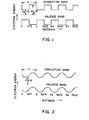
- Superlattice materials in this category include n-i-p-i... p-i-p-i ..., n-i-n-i ..., p-n-p-n ... structures where n, i, and p are n-type, intrinsic and p-type sublayers. Examples of energy band diagrams for the two classes of superlattice materials described above are shown in Fig. 1 and 2.
- Figure 1 shows a schematic energy-band diagram of a semiconductor superlattice structure having undoped crystalline layers where the alternating layers have substantially different compositions and the thickness of each layer is d/2.
- Figure 2 shows a schematic energy-band diagram of a superlattice structure having alternating layers, whose composition differs only in the dopant content, such as would be obtained in a n-i-p-i-n-i-p-i structure for example. See, for-example, L. Esaki et al., U.S. 3,626,357 and R. Dingle et al., U.S. 4,163,237.
- amorphous semiconductors and insulators can be deposited by a variety of means, reactive sputtering and plasma-assisted chemical vapor deposition (PCVD) being the most popular, in the amorphous state in a substantially defect-free form (PCVD is also known as glow discharge deposition.)
- substantially defect-free we mean free of chemically and electrically active coordination defects such as dangling bonds, to a level of better than about 1 defect per 10 5 atoms. This defect-free property manifests itself as a low density of states in the gap, as measured for example, by the optical absorption coefficient for photons with an energy less than the optical bandgap.
- amorphous silicon deposited by plasma assisted CVD from silane gas the low density of defects is known to result from the passivation of dangling Si bonds by atomic hydrogen.
- the hydrogen content of these materials depends on the deposition conditions.
- the materials will be represented by the nomenclature a-Si:H, in the case of amorphous hydrogenated silicon, where the hydrogen content is understood to depend on the detailed nature of the film preparation process.
- the present invention provides, from one aspect, a multilayered material, for example with non-periodic layers, having graded properties wherein the layers forming the material are made of semiconductor or insulator material, which may for example be amorphous, the interfaces between said layers being smooth and having a thickness less than about 500A, for example less than about 5A.
- the present invention provides from another aspect a multi-layered material having graded properties wherein the layers forming the material are made of semiconductor or insulator material which may be amorphous, the layers having a thickness less than an optical wavelength in the material divided by six (6).
- Embodiments of the present invention may include multi-layered structures (hereinafter referred to as "super-lattices”) with substantially smooth sub-layers, only a few atomic layers thick (5-500A), which can be fabricated from amorphous semiconductors and insulators while simultaneously maintaining their substantially defect-free properties.
- super-lattices multi-layered structures
- 5-500A atomic layers thick
- the amorphous superlattice materials have a variety of uses in optical and electronic applications as in the case of the crystalline superlattice materials. They can be used as antireflection coatings and optical filters.
- the graded properties may be obtained through variation of the thicknesses of the individual layers in the multilayered material.
- the gradation of physical properties of the multi-layered material may be a manifestation of the change in the optical gap across the material in a direction perpendicular to the plane of the layers.
- the gradation of physical properties may also be a manifestation of an effective medium effect in multi- layered material whose layers have different values for a given physical quantity (i.e., index of refraction) and whose layers have relative thicknesses which vary in a predetermined way to achieve a predetermined average value.
- the interfaces between the layers have a thickness less than about 5A.
- the layers have a thickness less than one sixth of an optical wavelength in the material.
- the graded property is the index of refraction so that the material may be used as an anti-reflection coating.
- Fig. 3 shows a schematic diagram of one embodiment of the present invention.
- the embodiment is a composition of matter which comprises a multilayered material whose layers are thin sheets of semiconducting or insulating tetrahedrally bonded amorphous material.
- the material has graded properties brought about by the fact that the layers have a spatially varying periodicity.
- the interface between the layers have a thickness less than about 5A or less than one sixth of an optical wavelength in the material.
- the entire structure is a multilayered thin film material, that is a material that is less than about 10 microns thick, with each layer less than 1000A thick.
- the first and alternate layers 1, 3, 5 of the structure have the same given composition while the second and alternate layers 2, 4, 6 ... have the same composition different from the given composition of layers 1, 3, 5 .... That is, layer 3 plus layer 4 is a repeat of the composition of layer 1 plus layer 2, etc.
- the compositional repeat varies in thickness so as to grade the properties of the material.
- the optical bandgap of the composition may differ from that of materials comprising the individual layers.
- the repeat distance is less than 1000A.
- a material may be regarded as being homogeneous from the point of view of optical properties as long as the inhomogeneities in composition occur over a length scale small compared to the wavelength of light in the material divided by six (see for example Stephens and Cody, Solar Energy Materials 1, 397 (1979)).
- the material may be regarded as a continuum optically, with the optical properties of an equivalent effective medium.
- the optical properties of such an effective medium can be graded, by for example changing the density or properties of the inhomogeneous inclusions.
- amorphous semiconductors In amorphous semiconductors the density of states edges are broader, being broadened by the structural disorder of the amorphous network in addition to the thermal motion of the atoms.
- the width of the low energy absorption tail of the optical absorption edge is one measure of the sharpness of the band edges in amorphous or crystalline semiconductors.
- an objective measure of the position of the band edges can be defined for both crystalline or amorphous semiconductors by, for example, the energy at which the density of.states of the bulk material drops to 10 20 cm- 3 ev.- l
- energy band diagrams such as those shown in Figs. 1 and 2, as described above can equally well be applied to amorphous and crystalline semiconductors.
- the modulation in the band edge energies illustrated in Figs. 1 and 2 is obtained by modulation of the thin film composition.
- the interfacial regions between the layers of the composition of matter of the present invention are substantially defect free.
- substantially defect free we mean that there is less than about one atomic coordination defect at the interface corresponding to an electronic state in the bandgap of the material, per 10 3 atoms at the interface, taken to be a single monolayer of atoms.
- This density can be measured by the photothermal deflection technique (see W. Jackson and N. Amer, Physical Review B,25,5559, (1982) and corresponds to an optical absorbance of less than about 10- 4 , per interface, in the sub-gap region of the optical absorption spectrum.
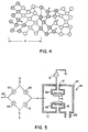
- FIG. 4 shows a schematic diagram of the lattice structure of a periodic superlattice in which the atoms of the alternating layers are indicated by light and dark circles and hydrogen atoms are indicated by light smaller circles.
- the period of the structures is d.
- the interface region is the junction region between two layers where the composition goes from one composition to another composition.
- the compositional change may be abrupt or continuous. That is, if the compositions of the adjacent layers are graded, then the compositional change may be continuous but the rate of change of the compositional gradation shall change at the interface.
- the TEM measurements show that the interfaces are smooth even after 1 m of material has been deposited. That is, the interface does not become progressively more complex and convoluted as the material grows thicker. This property is unexpected, and differs from the complex growth morphology normally observed in the growth of thin films well below their melting point (see, for example, Thin Film Phenomena, K. L. Chopra, R. E. Krieger Publishing Co., Huntington, NY 1979).
- Each individual layer of the composition of the present invention is substantially uniform in thickness.
- substantially uniform in thickness it is meant that the layer thicknesses varies by less than a few monolayers or 10% (whichever is larger) over lateral distances equal to several times the layer thickness.
- amorphous semiconducting and insulating materials that can be fabricated into amorphous semiconductor superlattices according to this invention, can be divided into two classes:
- Layers 1, 3, 5 ... and layers 2, 4, 6 ... may comprise any two of the materials where both are selected from the same class, e.g. a-Si:H/a-Si l - x N x :H or n-doped a-Si:H/p-doped a-Si:H.
- the alternating layers may include one material from class 1 alternating with a material from class 2, e.g. a-Si:H/n-doped a-Si l - x N x :H.
- compositions also include layered materials of the form n-i-p-i-n-i-p-i, where n and p are n-doped and p-doped material derived from an undoped amorphous semiconductor material, i, by the addition of small concentrations of n and p-type dopant, respectively.
- each layer 1, 3, 5 ... is considered to be n-i and each layer 2, 4, 6 ... is considered to p-i so that the spatial repeat distance is the thickness of n-i-p-i.
- the composition of matter also includes layered materials where the composition of each layer is modulated across the layers.
- the alternating layers are a-Si:H and a-Ge:H alloys
- the transition from a-Si:H to a-Ge:H and from a-Ge:H to a-Si:H may occur gradually over the layer thicknesses starting with a-Si:H, gradually increasing the percentage of a-Ge:H until it is all a-Ge:H.
- the percentage of a-Si:H is increased until it is all a-Si:H. All succeeding layers repeat this sequence.
- the materials in the two groups can be prepared by glow dischange decomposition of gaseous mixtures of volatile hydrides, fluorides or chlorides or of the elemental gases themselves in the case of 0 2 , N 2 , C1 2 and F 2 , as described below.
- a PCVD apparatus for carrying out the fabrication of the material of the present invention is designated as 2.
- the PCVD apparatus includes a vacuum chamber typically of stainless steel.
- Electrode 6 is grounded and refered to as the anode.
- Electrode 8 is insulated from -the stainless steel chamber by insulator 10 and is referred to as the cathode.
- Flat heaters 12 are contained in the electrodes.
- Substrates 14 which can be insulators such as quartz or metals such as stainless steel are placed in good thermal contact with the electrodes.
- the plasma is produced by a low power (5-10 W) RF (13.5 MHz) discharge, by means of an RF generator 16 connected to the cathode.
- RF generator 16 connected to the cathode.
- the composition of the gas in the reactor 2 is changed periodically by opening and closing alternately neumatic valves 18 and 20 to admit gas A or gas B into the reactor.
- the gases A and B are alternatively shunted into a ballast pump 26 by opening and closing valves 22 and 24 in phase with valves 18 and 20, respectively.
- the gases are pumped continuously out of the reactor by a pump through outlet 28.
- the molecular residence time TR is given by where V is the volume of the reactor, p is the gas pressure in the reactor and F o is the gas flow rate at standard pressure p o .
- the sub layer thickness is given by the product of the deposition rate and the flow period of the gas. The thickness of the sublayers can be varied from a submonolayer to thousands of angstroms.
- Example of amorphous semiconductor superlattice that have been produced include:
- Amorphous semiconductor n-i-p-i, p-i-p-i, p-n-p-n, n-i-n-i superlattice structures can be formed by any of the methods described above by changing periodically the dopant concentration in the gas. For example by flowing into the reactor first SiH 4 + 1% PH 3 , then SiH 4 and then SiH 4 + 1% B 2 H 6 and repeating this sequence periodically we obtain an amorphous semiconductor n-i-p-i superlattice.
- the change in the bandgap of the composition of matter of the present invention with layer thickness is believed to be due to quantum effects brought about by the dimensions of the layered material.
- the quantum effects also manifest themselves in the electrical properties of the material.
- the quantum effects brought about by the dimensions of the layered material are expected to have an appreciable effect on the properties of the material only if the energy level shifts introduced by the quantum effect are greater than about kT, where T is the temperature at which the properties are measured ( ⁇ 25 mev at room temperature).
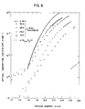
- optical absorption coefficient a as a function of photon energy E is shown in Figure 6 for four different superlattice materials all with the same a-Si l - x N x :H sublayer thickness ( -35A) but with the a-Si:H sublayer thickness varying from about 50A to about 10A.
- the optical absorption of the superlattice materials cannot be represented as a linear combination of the two constituents. Not only does the magnitude of the optical gap change with a-Si:H sublayer thickness, but also the slope of the low energy exponential part of the absorption edge changes with a-Si:H layer thickness, as illustrated in Fig. 6.
- the optical gap of the superlattice material would be expected to be wider than the optical gap of bulk a-Si:H by h 2 /8m * L 2 where h is Planck's constant, m * is the effective mass for electrons in a-Si:H and L is the a-Si:H sublayer thickness.
- the optical bandgap would be a linear function of 1/L 2 .
- the electrical resistivity of a series of a-Si:H/a-Si l-x N x :H superlattice materials has been studied, both the resistivity in the plane of the sub- layers and the resistivity perpendicular to the sub- layers.
- the resistivity in the plane of the sublayers was determined.
- the superlattice material was deposited on two predeposited Cr/n+ as-Si:H fingers, through a circular (5mm diameter hole) shadow mask spaced a few tenths of a millimeter above the substrate so as to produce a tapered thickness penumbra few tenths of a millimeter wide around the perimeter of the film. This approach ensures electrical contact to all of the sub- layers in the sometimes highly anisotropic superlattice materials.
- Perpendicular resistivity measurements were performed on films deposited on Cr/N + a-Si:H coated quartz substrates, which forms an ohmic contact to a SiH. A similarly ohmic contact was made to the top surface of the superlattice film with 2mm 2 area Cr/n + a-Si:H dots.
- the room temperature resistivity in the plane of the sublayers is plotted in Figure 7 as a function of L- 2 for the same series of a-Si:H/a-Si 1-x N x :H superlattice materials which had been studied optically.
- the resistivity in Figure 7 is normalized to the resistivity of the superlattice with the thickest a-Si:H sublayer, which was 1500A thick.
- the anisotropy in the electrical resistivity, of the a-Si:H/a-Si l-x N x :H superlattice materials namely the ratio of the perpendicular resistivity to the in-plane resistivity, varied from > 10 8 for the thick a-Si:H sublayer material to order 10-100 in the thin a-Si:H sublayer material.
- the larger anisotropy for the large L material where L is the thickness of the a-Si:H sublayers (a-Si l-x N x :H sublayer held at 35A) confirms the x-ray structural results, namely that thin, laterally coherent amorphous films have been fabricated.
- the reduction in anisotropy for the small L material results from the much larger in-plane resistivity in this material.
- the magnitude of the optical absorption coefficient for photon energies less than the optical absorption threshold is a commonly used figure of merit in the characterization of the defect density in semiconductor materials.
- a-Si:H it is well-known that structural defects such as dangling bonds show up as a low energy absorption shoulder whose magnitude is proportional to the density of defects.
- the optical absorption coefficient in the weakly absorbing subband- gap region is most easily determined from the photoconductivity response spectrum as measured using the technique of Triska et al. (Sol. State Commun. 1981) for example.
- the absolute magnitude of the low energy absorption is then determined by a match of the high energy part of the photoconductivity spectrum to optical transmission measurements.
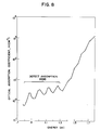
- optical absorption coefficient a determined as outlined above for photon energies in the vicinity of the optical gap and-lower, is shown in Figure 8 for an amorphous semiconductor superlattice material comprising alternating 1500A a-Si:H layers and 35A a-Si l-x N x :H layers.
- the oscillations in the optical absorption are caused by interference fringes generated by reflections at the film-substrate interface and the film-air interface.
- the optical absorption coefficient for the bulk material is the average of the interference maxima and minima on a logarithmic scale.
- optical absorption at 1.2 ev of about 3 cm ' 1 in Figure 8 is equivalent to a density of defect states of order 10 16 cm- 3 /ev, which corresponds to approximately one defect in 10 7 atoms.
- This defect density is comparable to the defect density in conventional nominally homogeneous a-Si:H films prepared under the same conditions.
- layered amorphous semiconductors An important test of the structural perfection of layered amorphous semiconductors is the ability of periodic layered amorphous semiconductors to diffract x-rays.
- the layered films act as a one dimensional diffraction grating, giving rise to character- stic diffraction according to Bragg's law: where ⁇ is the Bragg angle corresponding to the m th order diffraction, d is the repeat distance of the superlattice and ⁇ is the wavelength of the x-ray.
- Figure 9 the characteristic diffraction pattern of an amorphous semiconductor superlattice consisting of 40 periods deposited on a quartz substrate. Each period consists of a 40 ⁇ thick sublayer of a-Si:H/a-Si 1-x H x :H and a 30R thick sublayer of a-Si 1-x N x :H.
- Another way of checking the perfection of the superlattice is by transmission electron microscopy of a thin section perpendicular to the interfaces.
- FIG. 10 shows a transmission electron microscope picture of a layered a-Si:H/a-Si l-x N x :H amorphous semiconductor superlattice material with a periodic repeat distance of about 50 ⁇ / This figure further demonstrates the existence of nearly atomically abrupt and substantially smooth interfaces.
- multilayer material consists of alternating layers of hydrogenated amorphous silicon (a-Si:H) and hydrogenated amorphous silicon carbide (a-SiC:H)
- the optical bandgap of the material begins to increase above that of conventional unlayered a-Si:H films, prepared under the same conditions, when the a-Si:H layers are less than about 30A thick.
- Fig. 11 shows a schematic diagram of the band diagram for the above-described material wherein energy is plotted vs. distance.
- a material in which the composition is the same as a mixture of equal parts of a-Si:H and -a-SiC:H grown with the following layered structure.
- the first layer consists of 30A of a-Si:H, the next layer 29A of a-SiC:H, the next 28A of a-Si:H, followed by 27A of a-SiC:H etc... finished with 5A of a-SiC:H.
- This material will have an optical gap, Eg, of about 1.7 ev corresponding to a-Si:H and an optical gap, EG, of about 1.95 ev corresponding to the mean bandgap, halfway between a-Si:H (1.7 ev) and a-SiC:H (typical value 2.2 ev).
- Materials with graded optical bandgaps of this type are useful in vidicon- type image pick-up tubes as described by Hirai and Maruyama in Chapter 6 of Japan Annual Reviews in Electronics Computers and Telecommunications, Amorphous Semiconductor Technologies and Devices, North Holland, ed. by Y. Hamakawa, 1982.
- internal optical gap we mean an optical gap as determined by a probe of the electronic structure that is only sensitive to a 20-30A thick surface layer, such as UV photoemission, as discussed by L. Ley in Topics in Applied Physics, Vol. 56, The Physics of Hydrogenated Amorphous Silicon II, ed. J. D. Joannopoulos and G. Lucovsky, Springer Verlag 1984, for example.
- the short circuit current with a single layer AR coating is about 15% less than it would be with a perfect AR coating (B. Abeles et al., Thin Solid Films 90, 441, 1982). The difference will be somewhat larger in amorphous silicon solar cells with an extended spectral response ("optical enhancement").
- the single layer AR coat should be even more deficient in the case of crystalline silicon solar cells because of the relatively wider spectral response (400-1000 nm vs. 400-700 nm for a-Si).
- surface texturing introduced by the wafer sawing operation and index grading associated with encapsulated and dopant diffusion in conventional crystalline silicon cells combine to reduce the net reflectivity to 8-10%.
- a new form of graded index anti-reflection coating based on plasma CVD deposited graded superlattice structures is shown schematically in Fig. 12.
- One deposits high and low index materials in layers that are thinner than an optical wavelength so that they act as an effective medium with an index intermediate between the indices of the two constituents.
- the schematic diagram of Fig. 7 shows a particular example for the constituent elements of the solar cell. It is understood that other multi- layered materials may be used.
- a suitable amorphous silicon or crystalline silicon heterojunction solar cell structure which utilizes the layered AR coatings is illustrated in Fig. 12 and the corresponding index of refraction profile in Fig. 3.
- the layered structures in Fig. 12 and Fig. 13 have other advantages:
Landscapes
- Chemical & Material Sciences (AREA)
- Engineering & Computer Science (AREA)
- Nanotechnology (AREA)
- Chemical Kinetics & Catalysis (AREA)
- Mechanical Engineering (AREA)
- Biophysics (AREA)
- Crystallography & Structural Chemistry (AREA)
- Life Sciences & Earth Sciences (AREA)
- Physics & Mathematics (AREA)
- Materials Engineering (AREA)
- Optics & Photonics (AREA)
- Metallurgy (AREA)
- Organic Chemistry (AREA)
- Laminated Bodies (AREA)
- Photovoltaic Devices (AREA)
- Formation Of Insulating Films (AREA)
- Junction Field-Effect Transistors (AREA)
- Recrystallisation Techniques (AREA)
Applications Claiming Priority (2)
| Application Number | Priority Date | Filing Date | Title |
|---|---|---|---|
| US64533484A | 1984-08-29 | 1984-08-29 | |
| US645334 | 1984-08-29 |
Publications (2)
| Publication Number | Publication Date |
|---|---|
| EP0173566A2 true EP0173566A2 (fr) | 1986-03-05 |
| EP0173566A3 EP0173566A3 (fr) | 1987-10-21 |
Family
ID=24588595
Family Applications (1)
| Application Number | Title | Priority Date | Filing Date |
|---|---|---|---|
| EP85306113A Withdrawn EP0173566A3 (fr) | 1984-08-29 | 1985-08-29 | Matériau à couches multiples à changement graduel de propriétés |
Country Status (2)
| Country | Link |
|---|---|
| EP (1) | EP0173566A3 (fr) |
| JP (1) | JPS61190919A (fr) |
Cited By (2)
| Publication number | Priority date | Publication date | Assignee | Title |
|---|---|---|---|---|
| WO2003019244A1 (fr) * | 2001-08-24 | 2003-03-06 | General Electric Company | Article a revetement optique et procede de fabrication correspondant |
| US10707367B2 (en) | 2011-06-17 | 2020-07-07 | International Business Machines Corporation | Contact for silicon heterojunction solar cells |
Family Cites Families (2)
| Publication number | Priority date | Publication date | Assignee | Title |
|---|---|---|---|---|
| US4163237A (en) * | 1978-04-24 | 1979-07-31 | Bell Telephone Laboratories, Incorporated | High mobility multilayered heterojunction devices employing modulated doping |
| JPS6028268A (ja) * | 1983-07-26 | 1985-02-13 | Agency Of Ind Science & Technol | 半導体装置 |
-
1985
- 1985-08-29 JP JP60188684A patent/JPS61190919A/ja active Pending
- 1985-08-29 EP EP85306113A patent/EP0173566A3/fr not_active Withdrawn
Cited By (2)
| Publication number | Priority date | Publication date | Assignee | Title |
|---|---|---|---|---|
| WO2003019244A1 (fr) * | 2001-08-24 | 2003-03-06 | General Electric Company | Article a revetement optique et procede de fabrication correspondant |
| US10707367B2 (en) | 2011-06-17 | 2020-07-07 | International Business Machines Corporation | Contact for silicon heterojunction solar cells |
Also Published As
| Publication number | Publication date |
|---|---|
| JPS61190919A (ja) | 1986-08-25 |
| EP0173566A3 (fr) | 1987-10-21 |
Similar Documents
| Publication | Publication Date | Title |
|---|---|---|
| US4684565A (en) | X-ray mirrors made from multi-layered material | |
| US4598164A (en) | Solar cell made from amorphous superlattice material | |
| US4590399A (en) | Superlattice piezoelectric devices | |
| Hirose et al. | Electronic properties of chemically deposited polycrystalline silicon | |
| Kakalios et al. | Properties of amorphous semiconducting multilayer films | |
| Ye et al. | Structural, electrical, and optical properties of Ti-doped ZnO films fabricated by atomic layer deposition | |
| Abeles et al. | Amorphous semiconductor superlattices | |
| US4863245A (en) | Superlattice electrooptic devices | |
| US4642144A (en) | Proximity doping of amorphous semiconductors | |
| Wickboldt et al. | High performance glow discharge a-Si 1− x Ge x: H of large x | |
| US5242505A (en) | Amorphous silicon-based photovoltaic semiconductor materials free from Staebler-Wronski effects | |
| EP0122047B1 (fr) | Matériau semi-conducteur amorphe à plusieurs couches | |
| Tiedje et al. | Recent experimental results on a-Si: H/a-Ge: H superlattice structures | |
| Palafox et al. | Physical properties of CdS and CdS: In thin films obtained by chemical spray over different substrates | |
| Heo et al. | (Sn, Al) O x Films Grown by Atomic Layer Deposition | |
| Kumagai et al. | Bayesian optimization of hydrogen plasma treatment in silicon quantum dot multilayer and application to solar cells | |
| Jiang et al. | Shift of optical absorption edge in SnO2 films with high concentrations of nitrogen grown by chemical vapor deposition | |
| EP0173566A2 (fr) | Matériau à couches multiples à changement graduel de propriétés | |
| EP0154504A2 (fr) | Dispositifs électro-optiques comprenant un super-réseau | |
| Abeles et al. | Amorphous semiconductor superlattices | |
| Graeff et al. | Structural and optoelectronic properties of Ge‐rich hydrogenated amorphous silicon‐germanium alloys | |
| Mazurczyk et al. | Deposition and properties of a-GexCy: H-based superlattice structures | |
| Averin et al. | Optical properties of nickel oxide epitaxial nanofilms grown on LiNbO3 substrates and diode structures based on them | |
| Kumagai et al. | Discover Nano | |
| Zaka et al. | Physics based optical modeling of iron disulfide thin films |
Legal Events
| Date | Code | Title | Description |
|---|---|---|---|
| PUAI | Public reference made under article 153(3) epc to a published international application that has entered the european phase |
Free format text: ORIGINAL CODE: 0009012 |
|
| AK | Designated contracting states |
Kind code of ref document: A2 Designated state(s): DE FR GB |
|
| PUAL | Search report despatched |
Free format text: ORIGINAL CODE: 0009013 |
|
| RHK1 | Main classification (correction) |
Ipc: H01L 29/14 |
|
| AK | Designated contracting states |
Kind code of ref document: A3 Designated state(s): DE FR GB |
|
| STAA | Information on the status of an ep patent application or granted ep patent |
Free format text: STATUS: THE APPLICATION IS DEEMED TO BE WITHDRAWN |
|
| 18D | Application deemed to be withdrawn |
Effective date: 19880422 |
|
| RIN1 | Information on inventor provided before grant (corrected) |
Inventor name: TIEDJE, JOHN THOMAS Inventor name: ABELES, BENJAMIN |