EP0173578A2 - Druckvorrichtung - Google Patents
Druckvorrichtung Download PDFInfo
- Publication number
- EP0173578A2 EP0173578A2 EP85306176A EP85306176A EP0173578A2 EP 0173578 A2 EP0173578 A2 EP 0173578A2 EP 85306176 A EP85306176 A EP 85306176A EP 85306176 A EP85306176 A EP 85306176A EP 0173578 A2 EP0173578 A2 EP 0173578A2
- Authority
- EP
- European Patent Office
- Prior art keywords
- cooling
- printing
- temperature
- printing head
- printing device
- Prior art date
- Legal status (The legal status is an assumption and is not a legal conclusion. Google has not performed a legal analysis and makes no representation as to the accuracy of the status listed.)
- Granted
Links
- 238000001816 cooling Methods 0.000 claims abstract description 79
- 230000003750 conditioning effect Effects 0.000 claims description 8
- 230000000694 effects Effects 0.000 description 10
- 230000007423 decrease Effects 0.000 description 4
- 238000010586 diagram Methods 0.000 description 4
- 230000004913 activation Effects 0.000 description 1
- 230000003247 decreasing effect Effects 0.000 description 1
- 230000010365 information processing Effects 0.000 description 1
- 238000000034 method Methods 0.000 description 1
Images

Classifications
-
- B—PERFORMING OPERATIONS; TRANSPORTING
- B41—PRINTING; LINING MACHINES; TYPEWRITERS; STAMPS
- B41J—TYPEWRITERS; SELECTIVE PRINTING MECHANISMS, i.e. MECHANISMS PRINTING OTHERWISE THAN FROM A FORME; CORRECTION OF TYPOGRAPHICAL ERRORS
- B41J29/00—Details of, or accessories for, typewriters or selective printing mechanisms not otherwise provided for
- B41J29/377—Cooling or ventilating arrangements
-
- B—PERFORMING OPERATIONS; TRANSPORTING
- B41—PRINTING; LINING MACHINES; TYPEWRITERS; STAMPS
- B41J—TYPEWRITERS; SELECTIVE PRINTING MECHANISMS, i.e. MECHANISMS PRINTING OTHERWISE THAN FROM A FORME; CORRECTION OF TYPOGRAPHICAL ERRORS
- B41J2/00—Typewriters or selective printing mechanisms characterised by the printing or marking process for which they are designed
- B41J2/22—Typewriters or selective printing mechanisms characterised by the printing or marking process for which they are designed characterised by selective application of impact or pressure on a printing material or impression-transfer material
- B41J2/23—Typewriters or selective printing mechanisms characterised by the printing or marking process for which they are designed characterised by selective application of impact or pressure on a printing material or impression-transfer material using print wires
- B41J2/30—Control circuits for actuators
Definitions
- the present invention relates to an improvement in a printing device, and more particularly to a printing device provided with cooling means suitable for a wire dot impact system.
- the representative systems which have been employed in printing devices are e.g. a wire dot impact system, an ink jet system, and a thermal recording system etc.
- the printing devices of the wire dot impact system which is most popular among these systems have an increasing requirement of low noise in addition to needs of improvement in printing quality and printing speed etc.
- the printing devices of wire dot impact system are operative to drive a plurality of wires by means of a solenoid to effect printing operation, resulting in a large operating noise.
- Such printing devices of wire dot impact system are provided with cooling means in order to prevent seizure etc. of a printing head due to heat produced from the printing head.
- a cooling fan driven by a motor is ordinarily employed as the cooling means.
- such an operating noise is felt to be extremely offensive to the ear in an office of silence etc.
- the prior art printing devices are configured such that the. cooling fan becomes operative at the same time when powered. Accordingly, an operating noise of the cooling fan occurs even when the printing head does not effect printing operation. In addition, because the operating noise is approximately proportional to air draft, there is a tendency that a printing device having a higher cooling effect exhibits a larger operating noise.
- the conventional printing devices are required to always operate the cooling fan in order not to lower cooling effect. As a result, they are extremely noisy because of the operating noise of the cooling fan in addition to the operating noise of the printing head.
- an object of the present invention is to provide a printing device operative to control the operation of cooling means in accordance with a temperature of the printing head thus suppressing an operating noise of the cooling means as small as possible.
- Fig. 1 shows a circuit arrangement of a first preferred embodiment of a printing device according to the present invention.
- the printing device comprises a printing head 1 of wire dot impact system for effecting a printing operation, a carriage motor 2 for moving a carriage (not shown) on which the printing head 1 is mounted, a cooling fan 3 for forcedly cooling the printing head 1, a printing head drive circuit 4 for driving the printing head 1, a carriage motor control circuit 5 for contorolling the number of revolutions of the carriage motor 2, a printing control circuit 6 for controlling the operation of the printing head drive circuit 4, and a fan control circuit 7 for controlling the operation of the cooling 3.
- the printing device further comprises a temperature sensor 8 associated with the printing head 1 to sense a temperature of the printing head 1 to produce a corresponding electric signal, a sensor signal conditioning circuit 9 responsive to an output signal from the temperature sensor 8 to produce an information to be referred to later, and an entire control circuit 10 to effect a supervisory control of the above-mentioned circuits.
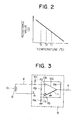
- the temperature sensor 8 employed in the first embodiment represents a temperature characteristic (a negative temperature characteristic) such that resistance value decreases according as temperature of the printing head 1 increases.
- the sensor signal conditioning circuit 9 comprises, as shown in FIg. 3, a differential amplifier 11 functioning as a hysteresis comparator and resistors R 2 to R6.
- the hysteresis comparator 9 is operative to respond to an input voltage varying according to a sense level of the temperature sensor 8 constituted by a resistor (negative resistance element) R 1 and a reference voltage to produce a predetermined output.
- an input voltage determined by the resistor R 2 and the resistor R constituting the temperature sensor 8 is applied to an inverting input terminal 11 a of the comparator 1 through a signal line d, and a reference voltage V determined by resistors R 3 , R 4 , R 5 and R 6 is applied to a non-inverting input terminal 11b of the comparator 12.
- a power source of the sensor signal conditioning circuit 9 is symboled by V cc .
- a reference voltage V 1 obtained when temperature of the resistor R 1 constituting the tenperature sensor 8 is increasing is expressed where R A denotes a resultant resistance value of the resistor R 4 and R 5 connected in parallel.
- a reference voltage V 2 obtained when temperature of the resistor R 1 is decreasing is expressed where R B denotes a resultant resistance value of the resistors R 5 and R 6 connected in parallel.
- the comparator 11 when a voltage applied to the inverting input terminal 11a of the comparator 11 is less than the reference voltage Vi as a result of an increase in temperature of the resistor R j, the comparator 11 is operative to produce a signal of H level from an output line e.
- the comparator 1 1 when a voltage applied to the inverting input terminal 11a of the comparator 11 is above the refernece voltage V 2 as a result of a decrease in temperature of the resistor R 1 , the comparator 1 1 is opearative to produce an output of L level from the output line e.
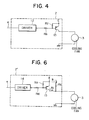
- the cooling fan control circuit 7 in the first embodiment comprises, as shown in Fig. 4, a driver integrated circuit (IC) 12, a pnp transistor 13 for controlling a drive current for the cooling fan 3, a resistor R 7 connected between the emitter and the base of the transistor 13, and an input resistor R 8 .
- IC driver integrated circuit
- R 7 resistor connected between the emitter and the base of the transistor 13
- R 8 input resistor
- the driver IC 12 is connected on its input side to the output line e of the comparator 11 provided in the sensor signal conditioning circuit 9 shown in Fig. 3, and is connected on its output side to the base of the transistor 13.
- the cooling fan 3 in this embodiment is driven by a dc motor connected between the collector of the transistor 13 and graound.
- a power source E for driving the dc motor is connected to the emitter of the transistor 13. Accordingly, rotational speed control of the dc mortor is carried out by controlling a base current of the transistor 13.
- the printing control circuit 6 outputs a signal to the printing head drive circuit 4 to initiate the printing operation of the printing head 1.
- the comparator 1 becomes operative to produce a signal of L level from the outout line e.
- the driver IC 12 produces an output of H level, with the result that no current flows into the base of the transistor 13. Accordingly, the cooling fan is stopped during this time period.
- the entire control circuit 10 detects that the cooling fan 3 has been operative to output a signal to the carriage motor control circuit 5 and the printing control circuit 6, thus effecting a control such that a printing speed of the printing head 1 is lowered.
- the comparator 11 becomes operative to output a signal of L level from the outout line e.
- the output of the driver IC 12 shifts to H level, with the result that no current flows into the base of the transistor 3, thus allowing cooling fan 3 to be stopped.
- the entire control circuit 10 detects that the cooling fan has been stopped to output a signal to the carriage motor control circuit 5 and the printing control circuit 6, thus increasing a printing speed of the printing head 1 to effect a control such that printing spped is returned to a normal speed.
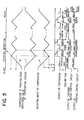
- an increase in the temperature of the printing head 1 is caused due to the printing operation, and at the time when the temperature rises to T 1 , the cooling fan 3 becomes operative and a printing operation is effected at a reduced printing spped. Thus, a discrease in the temperature of the printing head 1 occurs. At the time when the temperature lowers to T 2 , the cooling fan 3 is stopped and the printing head 1 is returned to a normal operation.
- the cooling fan 3 is inoperative. Accordingly, for most of a time interval during which the printing head effects a printing operation, the cooling fan 3 is not activated and there is no possibility that the cooling effect is lowered.
- the elementary configuration of the printing device in the second embodiment is common to that in the first embodiment.except for circuit configuration of the fan control circuit, and therefore the explanation in connection with the common parts will be omitted.
- the fan control circuit 7' in this embodiment comprises a driver IC 14, a transistor 15 for controlling a drive current for the cooling fan 3, and resistors R 9 , R 10 and R s .
- the driver IC 14 is connected on its input side to the output line e of the comparator 11 provided in the sensor signal conditioning circuit 9 shown in Fig. 3 and on its output side to the base of the transistor 15.
- the cooling fan 3 is driven by a dc motor connected between the collector of the transistor 13 and ground.
- a power source E for driving the DC motor is connected to the emitter of the transistor 15.
- the fan control circuit 7' in this embodiment is characterized in that the bypassing resistor R s is connected between the emitter and the collector of the transistor 15.
- the driver IC 14 when the temperature of the printing head 1 is less than T 1 shown in Fig. 5 and the comparator 1 1 is operative to output a signal of L level from the output line e, the driver IC 14 produces an output of H level, with the result that no current flows into the base of the transistor 15. Accordingly, a voltage obtained by substracting a value corresponding to a lower voltage drop by the resistor Rs from a supply voltage from the power supply line E is applied to the cooling San 3 through the resistor R3 (route l 1 ). As a result, the cooling fan 3 rotates at a reduced speed.
- the comparator 1 becomes operative to output a signal of H level from the output line e.
- the output of the driver IC 14 shifts to L level, with the result that a current flows into the base of the transistor 15 to turn on the transistor 15.
- a supply voltage is directly applied from the power supply line E to the cooling fan 3 (route 1 2 excluding the resistor Rs).
- the cooling fan 3 rotates at a normal speed.
- the printing speed control is effected such that when the cooling fan 3 rotates at a normal speed, the printing head effets a printing operation at a reduced speed, while when it rotates at a reduced speed, the printing head effects a printing operation at a normal speed.
- the fan control circuit 7 in the above-mentioned first embodiment is configured so that the cooling fan 3 becomes operative at the time when the temperature of the printing head 1 rises to T and it is stopped at the time when the temperature of the printing head 1 loweres to T 2 .
- the fan control circuit 7' in the second embodiment is configured so that the cooling fan 3 rotates at a reduced speed and then rotates at a normal speed at the time when the temperature of the printing head 1 rises to T1, and it rotates at a reduced speed at the time when the temperature of the printing head 1 lowers to T 2 . It is to be noted that the cooling fan rotates at a reduced speed until the temperature of the printing head 1 rises to T 1 in the second embodiment.
- the fan control circuits employed in the first and second embodiments may be selectively used depending upon conditions required for the cooling fan and conditions required for printing speed of the printing head.
- the dc motor is used as a motor for driving the cooling fan 3.
- the both embodiments are not limited to the dc motor.
- an ac motor as a motor for driving the cooling fan may allow the both embodiments to be put into practice by providing control means which can control rotational speed of the ac motor to control the rotational speed of the cooling fan in accordance with the temperature of the printing head.
Landscapes
- Accessory Devices And Overall Control Thereof (AREA)
Applications Claiming Priority (2)
| Application Number | Priority Date | Filing Date | Title |
|---|---|---|---|
| JP59182220A JPS6158783A (ja) | 1984-08-31 | 1984-08-31 | 印字装置 |
| JP182220/84 | 1984-08-31 |
Publications (3)
| Publication Number | Publication Date |
|---|---|
| EP0173578A2 true EP0173578A2 (de) | 1986-03-05 |
| EP0173578A3 EP0173578A3 (en) | 1987-04-29 |
| EP0173578B1 EP0173578B1 (de) | 1990-04-04 |
Family
ID=16114441
Family Applications (1)
| Application Number | Title | Priority Date | Filing Date |
|---|---|---|---|
| EP85306176A Expired EP0173578B1 (de) | 1984-08-31 | 1985-08-30 | Druckvorrichtung |
Country Status (5)
| Country | Link |
|---|---|
| US (1) | US4664542A (de) |
| EP (1) | EP0173578B1 (de) |
| JP (1) | JPS6158783A (de) |
| CA (1) | CA1246936A (de) |
| DE (1) | DE3576935D1 (de) |
Cited By (4)
| Publication number | Priority date | Publication date | Assignee | Title |
|---|---|---|---|---|
| DE3812622A1 (de) * | 1987-04-17 | 1988-11-03 | Hitachi Koki Kk | Steuereinrichtung fuer impactdrucker |
| EP0365122A1 (de) * | 1988-08-22 | 1990-04-25 | Seiko Epson Corporation | Schlagdrucker |
| US5042375A (en) * | 1989-04-27 | 1991-08-27 | Mannesmann Aktiengesellschaft | Device for temperature control of a print head or of a hammer block including an electromagnetic coil |
| CN103968890A (zh) * | 2014-04-23 | 2014-08-06 | 苏州经贸职业技术学院 | 一种温湿度及烟雾监测系统 |
Families Citing this family (15)
| Publication number | Priority date | Publication date | Assignee | Title |
|---|---|---|---|---|
| JPS61173975A (ja) * | 1985-01-29 | 1986-08-05 | Matsushita Electric Ind Co Ltd | 感熱記録装置 |
| US4842431A (en) * | 1986-10-15 | 1989-06-27 | Brother Kogyo Kabushiki Kaisha | Multi-speed cooling fan for printing device |
| JPS63126778A (ja) * | 1986-11-18 | 1988-05-30 | Brother Ind Ltd | 印字装置 |
| DE3752179T2 (de) * | 1986-12-10 | 1998-08-20 | Canon Kk | Aufzeichnungsgerät und Entladungsregeneriermethode |
| US4848943A (en) * | 1987-04-13 | 1989-07-18 | Micro Peripherals | Method and apparatus for energizing a printhead |
| US4791435A (en) * | 1987-07-23 | 1988-12-13 | Hewlett-Packard Company | Thermal inkjet printhead temperature control |
| DE69001911T2 (de) * | 1989-02-10 | 1993-09-23 | Seiko Epson Corp | Treiberschaltung fuer einen drahtpunktdruckknopf. |
| US5071240A (en) * | 1989-09-14 | 1991-12-10 | Nikon Corporation | Reflecting optical imaging apparatus using spherical reflectors and producing an intermediate image |
| JP2932744B2 (ja) * | 1991-05-10 | 1999-08-09 | ブラザー工業株式会社 | スタンプ装置 |
| US5211493A (en) * | 1992-06-05 | 1993-05-18 | Eastman Kodak Company | Cooling system for a thermal printing head |
| US5797329A (en) * | 1995-05-16 | 1998-08-25 | Dataproducts Corporation | Hot melt ink printer and method printing |
| US6196672B1 (en) * | 1997-06-27 | 2001-03-06 | Brother Kogyo Kabushiki Kaisha | Hot-melt type ink jet printer having heating and cooling arrangement |
| US6951378B1 (en) * | 1998-05-04 | 2005-10-04 | Canon Kabushiki Kaisha | Print control based on print head temperature |
| US20050094167A1 (en) * | 2003-10-31 | 2005-05-05 | Hewlett-Packard Development Company, L.P. | Method and apparatus of operating a printer |
| US8011840B2 (en) * | 2007-02-12 | 2011-09-06 | Toshiba Tec Kabushiki Kaisha | Warning notification at cover open in printer |
Family Cites Families (11)
| Publication number | Priority date | Publication date | Assignee | Title |
|---|---|---|---|---|
| US3377545A (en) * | 1966-01-17 | 1968-04-09 | Barber Colman Co | Thermostatic transducer for winter and summer operation |
| JPS55124684A (en) * | 1979-03-20 | 1980-09-25 | Nippon Telegr & Teleph Corp <Ntt> | Printing velocity controller |
| DE2929417C2 (de) * | 1979-07-20 | 1983-01-27 | Olympia Werke Ag, 2940 Wilhelmshaven | Elektronisches Gerät mit elektrischem Lüfter o.dgl. |
| JPS5654531A (en) * | 1979-10-08 | 1981-05-14 | Nippon Telegr & Teleph Corp <Ntt> | Variable wind speed air-cooled structure |
| JPS56151583A (en) * | 1980-04-28 | 1981-11-24 | Oki Electric Ind Co Ltd | Printer |
| JPS56162671A (en) * | 1980-05-21 | 1981-12-14 | Usac Electronics Ind Co Ltd | Temperature detection system for wire dot type printing head |
| JPS57148678A (en) * | 1981-03-11 | 1982-09-14 | Toshiba Corp | Impact dot printer |
| JPS57205179A (en) * | 1981-06-12 | 1982-12-16 | Oki Electric Ind Co Ltd | Thermal printer |
| JPS58129524A (ja) * | 1982-01-27 | 1983-08-02 | Canon Inc | 冷却フアン付電子機器 |
| JPS58160169A (ja) * | 1982-03-18 | 1983-09-22 | Shinko Electric Co Ltd | サ−マルプリンタ |
| DE3371016D1 (en) * | 1982-12-10 | 1987-05-21 | Micronel Ag | Ventilator with an electronically commutated d.c. motor |
-
1984
- 1984-08-31 JP JP59182220A patent/JPS6158783A/ja active Pending
-
1985
- 1985-08-20 CA CA000489037A patent/CA1246936A/en not_active Expired
- 1985-08-30 US US06/771,577 patent/US4664542A/en not_active Expired - Fee Related
- 1985-08-30 DE DE8585306176T patent/DE3576935D1/de not_active Expired - Lifetime
- 1985-08-30 EP EP85306176A patent/EP0173578B1/de not_active Expired
Cited By (4)
| Publication number | Priority date | Publication date | Assignee | Title |
|---|---|---|---|---|
| DE3812622A1 (de) * | 1987-04-17 | 1988-11-03 | Hitachi Koki Kk | Steuereinrichtung fuer impactdrucker |
| EP0365122A1 (de) * | 1988-08-22 | 1990-04-25 | Seiko Epson Corporation | Schlagdrucker |
| US5042375A (en) * | 1989-04-27 | 1991-08-27 | Mannesmann Aktiengesellschaft | Device for temperature control of a print head or of a hammer block including an electromagnetic coil |
| CN103968890A (zh) * | 2014-04-23 | 2014-08-06 | 苏州经贸职业技术学院 | 一种温湿度及烟雾监测系统 |
Also Published As
| Publication number | Publication date |
|---|---|
| CA1246936A (en) | 1988-12-20 |
| JPS6158783A (ja) | 1986-03-26 |
| DE3576935D1 (de) | 1990-05-10 |
| US4664542A (en) | 1987-05-12 |
| EP0173578A3 (en) | 1987-04-29 |
| EP0173578B1 (de) | 1990-04-04 |
Similar Documents
| Publication | Publication Date | Title |
|---|---|---|
| EP0173578B1 (de) | Druckvorrichtung | |
| US4510505A (en) | Thermal printer | |
| JPH047313B2 (de) | ||
| US5731671A (en) | Method and circuit arrangement for controlling fans | |
| JPS6337595B2 (de) | ||
| JPS63260461A (ja) | インパクトプリンタの制御装置 | |
| JPS615960A (ja) | 非安定化電源を用いた感熱記録方式 | |
| JPH07163182A (ja) | モータ制御方法およびモータ制御装置 | |
| US4896167A (en) | Image recording apparatus | |
| JPH06957A (ja) | インクジェットプリンタ | |
| CN85106823A (zh) | 印字装置 | |
| JPH06305164A (ja) | プリンタ及びその印字方法 | |
| JP2871252B2 (ja) | インクジェット記録装置 | |
| JPH028595B2 (de) | ||
| JP3284452B2 (ja) | インパクトプリンタ | |
| JP3299257B2 (ja) | インクジェットヘッド駆動電源回路 | |
| JPS6153054A (ja) | ドツトインパクト式印字装置 | |
| JPS61206657A (ja) | インクジエツト記録装置 | |
| JP3284553B2 (ja) | シリアル・プリンタ | |
| JPH0655760A (ja) | 印字ヘッド制御装置,ヘッド制御方法及びプリンタ | |
| JPH04294165A (ja) | サ−マルヘッド制御装置 | |
| JPH08156245A (ja) | インクジェットヘッド駆動電源回路 | |
| JPS59118477A (ja) | 感熱式プリンタ | |
| JPS63162254A (ja) | シリアルドツトプリンタ | |
| JP2908182B2 (ja) | シリアルプリンタ |
Legal Events
| Date | Code | Title | Description |
|---|---|---|---|
| PUAI | Public reference made under article 153(3) epc to a published international application that has entered the european phase |
Free format text: ORIGINAL CODE: 0009012 |
|
| 17P | Request for examination filed |
Effective date: 19850916 |
|
| AK | Designated contracting states |
Kind code of ref document: A2 Designated state(s): DE FR GB |
|
| PUAL | Search report despatched |
Free format text: ORIGINAL CODE: 0009013 |
|
| AK | Designated contracting states |
Kind code of ref document: A3 Designated state(s): DE FR GB |
|
| 17Q | First examination report despatched |
Effective date: 19890421 |
|
| GRAA | (expected) grant |
Free format text: ORIGINAL CODE: 0009210 |
|
| AK | Designated contracting states |
Kind code of ref document: B1 Designated state(s): DE FR GB |
|
| REF | Corresponds to: |
Ref document number: 3576935 Country of ref document: DE Date of ref document: 19900510 |
|
| ET | Fr: translation filed | ||
| PLBE | No opposition filed within time limit |
Free format text: ORIGINAL CODE: 0009261 |
|
| STAA | Information on the status of an ep patent application or granted ep patent |
Free format text: STATUS: NO OPPOSITION FILED WITHIN TIME LIMIT |
|
| 26N | No opposition filed | ||
| PGFP | Annual fee paid to national office [announced via postgrant information from national office to epo] |
Ref country code: FR Payment date: 19940809 Year of fee payment: 10 |
|
| PGFP | Annual fee paid to national office [announced via postgrant information from national office to epo] |
Ref country code: GB Payment date: 19940822 Year of fee payment: 10 |
|
| PGFP | Annual fee paid to national office [announced via postgrant information from national office to epo] |
Ref country code: DE Payment date: 19940823 Year of fee payment: 10 |
|
| PG25 | Lapsed in a contracting state [announced via postgrant information from national office to epo] |
Ref country code: GB Effective date: 19950830 |
|
| PG25 | Lapsed in a contracting state [announced via postgrant information from national office to epo] |
Ref country code: FR Effective date: 19960430 |
|
| GBPC | Gb: european patent ceased through non-payment of renewal fee |
Effective date: 19950830 |
|
| PG25 | Lapsed in a contracting state [announced via postgrant information from national office to epo] |
Ref country code: DE Effective date: 19960501 |
|
| REG | Reference to a national code |
Ref country code: FR Ref legal event code: ST |