EP0173794A2 - Dispositif pour extraire l'eau du linge mouillé - Google Patents
Dispositif pour extraire l'eau du linge mouillé Download PDFInfo
- Publication number
- EP0173794A2 EP0173794A2 EP85103650A EP85103650A EP0173794A2 EP 0173794 A2 EP0173794 A2 EP 0173794A2 EP 85103650 A EP85103650 A EP 85103650A EP 85103650 A EP85103650 A EP 85103650A EP 0173794 A2 EP0173794 A2 EP 0173794A2
- Authority
- EP
- European Patent Office
- Prior art keywords
- bell
- cylinder
- rods
- edge
- base
- Prior art date
- Legal status (The legal status is an assumption and is not a legal conclusion. Google has not performed a legal analysis and makes no representation as to the accuracy of the status listed.)
- Withdrawn
Links
Images


Classifications
-
- B—PERFORMING OPERATIONS; TRANSPORTING
- B30—PRESSES
- B30B—PRESSES IN GENERAL
- B30B9/00—Presses specially adapted for particular purposes
- B30B9/02—Presses specially adapted for particular purposes for squeezing-out liquid from liquid-containing material, e.g. juice from fruits, oil from oil-containing material
- B30B9/22—Presses specially adapted for particular purposes for squeezing-out liquid from liquid-containing material, e.g. juice from fruits, oil from oil-containing material using a flexible member, e.g. diaphragm, urged by fluid pressure
-
- D—TEXTILES; PAPER
- D06—TREATMENT OF TEXTILES OR THE LIKE; LAUNDERING; FLEXIBLE MATERIALS NOT OTHERWISE PROVIDED FOR
- D06F—LAUNDERING, DRYING, IRONING, PRESSING OR FOLDING TEXTILE ARTICLES
- D06F47/00—Apparatus of the press type for expelling water from the linen
Definitions
- the present invention relates to a device for dewatering wet laundry.
- Known devices of this type consist of a base plate with water drainage openings and a bell with an elastic membrane which can be put over a frame onto wet laundry placed there.
- the edge of the bell encloses the laundry.
- the membrane By filling in a liquid pressure medium, the membrane lies on the laundry and squeezes it out.
- the forces that occur are dissipated into the foundation under the press via the frame to which the bell is locked.
- This solution is structurally very complex. In addition, this process can only be carried out discontinuously for structural reasons.
- the object of the present invention is therefore to find a simpler solution which, at the same time, makes it possible to shorten the interruption times by switching on an intermediate clock and thus to handle larger throughputs.
- the solution to the problem consists in a device for dewatering wet laundry with the aid of a membrane arranged on a bellows that can be pressurized with pressure fluid and a floor underneath with outlets for squeezed water, which is characterized by a loose cylinder that can be placed on the floor separately from the bell upper and / or lower edge flanges, as well as a lifting device for the cylinder and / or the bell, which also acts as a lock and consists of rods with locking elements, as well as bushings in the bell edge, the edge flanges and the base, each one below the other and around the outer circumference of the cylinder are distributed and, after twisting, connect the bell, cylinder and base to each other in a non-positive manner.
- the forces exerted by the hydraulic fluid are completely absorbed by machine elements arranged on it.
- a portal construction with anchoring in the foundation or a derivation of the forces in the side walls while accepting high bending moments is not necessary.
- the process is very simple.
- the cylinder holding the laundry is loosely standing on the floor with drains. After the wet laundry has been filled in, the rods which hold the bell with the membrane via a lock are lowered until the edge of the bell lies on the upper edge of the cylinder.
- the rods are now unlocked and lowered through the bushings in the flanges and locked with both the bell and the floor.
- the locking mechanism can be a screw connection in the edge of the bell and the lower flanges of the cylinder and of the base, with simultaneous engagement of two threaded sections on the rod being assumed when closing.
- the screw connection is unscrewed from the floor, but remains connected to the lower flange.
- the cylinder together with the bell can be lifted off the rods and the pressed laundry removed: The cylinder is then lowered again and the rods are turned back further, which frees them from the lower cylinder flange.
- the lower threaded piece is lifted up and screwed into the bell in order to be lifted up with it for refilling.
- the rods only have to be moved by a few revolutions, and the bushings without threads must have a larger diameter than the thread.
- bushings are provided with elongated holes and the rods with toggles, which must be arranged at the lower end and in the upper area so that they rest on the bottom and on the upper edge of the bell .
- the number of bars and their diameter are determined by the tensile strength and by an even distribution of the forces on the bell edge and floor. With the help of the toggles, a 90 ° turn is sufficient to effect a locking from the lead-through position.-An arrangement of upper and lower flanges in a ring around the cylinder is preferred in order to be able to produce a rigid connection, as this causes the bell / top to be at the top and bottom Flange on the one hand, as well as bottom and lower flange on the other hand, fastening pairs arise.
- the elongated holes should preferably be aligned tangentially to the cylinder circumference.
- the gags themselves can protrude from the preferably round rods on one side (L-shaped) or on both sides (T-shaped). If an upper flange edge is arranged on the cylinder, a space must be left between the lower edge of the bell and the upper edge of the flange to accommodate the upper gag.
- the bars can be particularly advantageously in a common frame, e.g. be rotatably supported on a support plate and jointly lowered and locked, or unlocked and raised.
- a common kinematics can simultaneously turn the rods. For example, this is possible by means of a central spur gear with which gearwheels assigned to each rod, or, with a correspondingly low transmission ratio, also gearwheel sections which do not have to protrude beyond the edge of the plate, are in engagement.
- a very special advantage of the present invention is that two stations can now be operated in the carousel mode. This is achieved in a simple manner by means of two floor segments which can be pivoted about a common axis into a filling and an unloading position, and above them arranged their own cylinders, bells, rods with locking elements and support frames for lifting and lowering the cylinder and / or bell, the support frames being preferably designed to be drivable in synchronism with the base segments about the axis.
- the function is as follows. After filling and pressing, or during the latter, the cylinder in question is swiveled by 180 ° together with the bell and base segment. An emptied second cylinder standing on the segment is pivoted into the filling position, the bell of which is raised by means of the rods for filling. - After the squeezing process is finished, the toggles are released, moved from the base segment under the lower flanges and brought back into the closed position. The rods are lifted together with the cylinder and bell and these until the pressed laundry can be pushed onto a conveyor belt arranged next to it. Then the composite is lowered back onto the floor segment, the bars are unlocked and raised under the edge of the bell.
- the work of the device can be supported by a feed hopper which can be moved back and forth below the laundry outlet of the washing machine and which is retracted before the bell is lowered.
- the pressed laundry can be placed on a conveyor belt arranged next to the unloading position with the aid of a slide.
- FIG. 1 the cylinder 1 with filled wet laundry 22 is shown. He stands on a floor 6 with drains 14, -us which the free or squeezed fleet can run off. This floor is also known as a beater floor.
- the washing machine outlet 30 is shown on the left in the drawing.
- the bell 8 with the membrane 25 and the pressure medium connection 26 is located above the cylinder 1.
- FIG. 2 shows the closed state of the cylinder 1, in which the toggles 11 and 11 'hold the cylinder 1 between the bell 8 and the base 6.
- the filling funnel 18 is moved laterally, the membrane 25 is under pressure of the filled water 28, the wet laundry 22 is pressed out, the membrane 25 laying on the laundry 22.
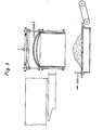
- Figure 3 shows the lifting of the cylinder 1 together with the bell 8. Pressurized water has been drawn off before or when lifting.
- the toggles 11 of the rods 9 lie below the lower flange 3. However, they can also be moved under the upper flange 2 for lifting.
- the slide moves the pressed laundry 20 to a conveyor belt, from where it is fed to the final drying.
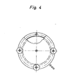
- FIG. 4 shows the top view of the locking and unlocking kinematics with the aid of the gear transmission 26, 27, the smaller wheels 27 driving the rods.
- a smaller transmission ratio is possible without a large projection of the wheels 27 connected to the rods by selecting circular segment-shaped wheel segments with larger radii, which can then only be pivoted back and forth.
- one of the elongated holes 5 of the bell rim 4 can be seen, as well as an L-shaped toggle pivoted in the closed position on the . Bell edge 4.
- a motor (not shown) moves the gear unit according to time periods that may be predetermined by program control, as does a cyclically adjustable lifting device (not shown).
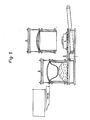
- FIG. 5 shows the carousel arrangement of two cylinders 1, the left one being pressurized with pressurized water. This rests on a base segment 16 and is locked with it. Left segment 16 and right segment 17 are pivotally mounted about a common axis 15 and can be driven by a motor.
- the right cylinder is raised, the pressed laundry 20 is placed on the conveyor belt 19 by means of the slide 21.
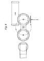
- FIG. 6 shows the top view of the carousel arrangement of FIG. 5.
- the left of the illustration shows the washing machine outlet 30 and the retracted filling funnel 18 arranged perpendicularly to the sheet plane below it.
Landscapes
- Engineering & Computer Science (AREA)
- Mechanical Engineering (AREA)
- Physics & Mathematics (AREA)
- Fluid Mechanics (AREA)
- Textile Engineering (AREA)
- Accessory Of Washing/Drying Machine, Commercial Washing/Drying Machine, Other Washing/Drying Machine (AREA)
- Separation Using Semi-Permeable Membranes (AREA)
Applications Claiming Priority (2)
| Application Number | Priority Date | Filing Date | Title |
|---|---|---|---|
| DE3413309 | 1984-04-09 | ||
| DE19843413309 DE3413309A1 (de) | 1984-04-09 | 1984-04-09 | Vorrichtung zum entwaessern von nasswaesche |
Publications (2)
| Publication Number | Publication Date |
|---|---|
| EP0173794A2 true EP0173794A2 (fr) | 1986-03-12 |
| EP0173794A3 EP0173794A3 (fr) | 1987-07-01 |
Family
ID=6233067
Family Applications (1)
| Application Number | Title | Priority Date | Filing Date |
|---|---|---|---|
| EP85103650A Withdrawn EP0173794A3 (fr) | 1984-04-09 | 1985-03-27 | Dispositif pour extraire l'eau du linge mouillé |
Country Status (3)
| Country | Link |
|---|---|
| US (1) | US4633685A (fr) |
| EP (1) | EP0173794A3 (fr) |
| DE (1) | DE3413309A1 (fr) |
Families Citing this family (6)
| Publication number | Priority date | Publication date | Assignee | Title |
|---|---|---|---|---|
| US4811658A (en) * | 1987-05-19 | 1989-03-14 | Arend B.V. | Apparatus and system for draining whey from cheese curd for manufacturing cheese |
| US5483402A (en) * | 1994-06-15 | 1996-01-09 | Quantum Corporation | Magneto resistive head having symmetric off-track performance profile |
| US20050084641A1 (en) * | 2004-05-14 | 2005-04-21 | Glue Dots International, Llc | Perforated adhesive dispensing sheets |
| ES1058441U (es) * | 2004-09-06 | 2004-12-16 | Maquinas Y Herramientas La Rioja, S.L. | Prensa vertical de frutas, uvas y sus derivados, del tipo cubillo-neumatica con membrana. |
| KR20160015253A (ko) | 2013-05-10 | 2016-02-12 | 쥬세로 인코퍼레이티드 | 착즙 시스템 및 방법 |
| US10543652B2 (en) | 2016-03-03 | 2020-01-28 | Fresh Press LLC | Press |
Family Cites Families (6)
| Publication number | Priority date | Publication date | Assignee | Title |
|---|---|---|---|---|
| BE402577A (fr) * | ||||
| US1034207A (en) * | 1912-04-17 | 1912-07-30 | Thomas E Corbett | Fruit-pressing device. |
| US3992905A (en) * | 1975-06-30 | 1976-11-23 | Mcgraw-Edison Company | Compression extractor device for laundry goods |
| DE2852923C2 (de) * | 1978-12-07 | 1983-06-23 | Hans F. 7120 Bietigheim-Bissingen Arendt | Taktpresse zur Entwässerung von Naßwäsche |
| DE2948671A1 (de) * | 1979-12-04 | 1981-06-11 | Hans F. 7120 Bietigheim-Bissingen Arendt | Taktpresse zur entwaesserung von nasswaesche |
| DE3109934A1 (de) * | 1981-03-14 | 1982-10-14 | Götz Patent & Technik Inh. I. Götz, 8600 Bamberg | Verfahren und vorrichtung zum auspressen von fluessigkeiten aus textilien, vliesen, filzen, haeuten und anderen wassergebundenen stoffen, insbes. zur entwaesserung von waescheposten |
-
1984
- 1984-04-09 DE DE19843413309 patent/DE3413309A1/de not_active Withdrawn
-
1985
- 1985-03-27 EP EP85103650A patent/EP0173794A3/fr not_active Withdrawn
- 1985-04-09 US US06/721,432 patent/US4633685A/en not_active Expired - Fee Related
Also Published As
| Publication number | Publication date |
|---|---|
| US4633685A (en) | 1987-01-06 |
| EP0173794A3 (fr) | 1987-07-01 |
| DE3413309A1 (de) | 1985-10-17 |
Similar Documents
| Publication | Publication Date | Title |
|---|---|---|
| EP0397082B1 (fr) | Procédé et dispositif pour la déshydratation de boues et de produits analoques | |
| EP0350777B1 (fr) | Procédé et appareil pour la production de fromage | |
| DE2715237C3 (de) | Einrichtung zur Vakuum-Imprägnierung von Platten eines porösen Werkstoffes | |
| DE2558248A1 (de) | Schmelzgeraet | |
| EP0013882A1 (fr) | Dispositif pour la production discontinue de blocs de mousse plastique | |
| EP0264899A2 (fr) | Dispositif de déshydratation de boues et de matières similaires | |
| DE2602845C2 (de) | Presse zum Auspressen von Flüssigkeit | |
| EP0173794A2 (fr) | Dispositif pour extraire l'eau du linge mouillé | |
| DE3119661C2 (de) | Vorrichtung zum Zuführen von Wäschestücken zu einer Mangel | |
| DE69005771T2 (de) | Membranpresse. | |
| EP0807605A2 (fr) | Dispositif pour le dessalage et le traitement d'eau | |
| EP0057732B1 (fr) | Procédé et dispositif pour la séparation de liquides à partir de structures hétérogènes liquides-solides, par exemple procédés pour déshydrater et épaissir des boues communales ou industrielles | |
| DE166150C (fr) | ||
| DE60206021T2 (de) | Anlage zur weinherstellung | |
| DE445728C (de) | Verfahren und Vorrichtung zur Herstellung von Alkalicellulose aus mit Alkalilauge getraenkten Zellstoffblaettern | |
| DE2801436A1 (de) | Vorrichtung zum trennen von pressplatten, insbesondere in filterpressen | |
| DE1800766A1 (de) | Verfahren zum Entwaessern von Kaese-Bruch und zum Formen von Kaese | |
| EP1136213A2 (fr) | Procédé et dispositif de fabrication automatique de corps creux à partir d'un mélange | |
| DE3634736A1 (de) | Maschine zur herstellung von rohrfoermigen bewehrungskoerpern fuer betonrohre | |
| AT378737B (de) | Presse zur verdichtung von altmaterial | |
| DE521297C (de) | Roehrenformmaschine | |
| DE2548193A1 (de) | Vorrichtung zum entfernen von fluessigkeiten aus feststoffen | |
| DE102004024626A1 (de) | Waschanlage mit Entwässerungseinheit | |
| DE673520C (de) | Vorrichtung zum Herstellen von Baukoerpern, wie Saeulen, Kapitellen, Rohren | |
| DE1161661B (de) | Formmaschine mit um eine senkrechte Achse kontinuierlich umlaufendem Drehtisch |
Legal Events
| Date | Code | Title | Description |
|---|---|---|---|
| PUAI | Public reference made under article 153(3) epc to a published international application that has entered the european phase |
Free format text: ORIGINAL CODE: 0009012 |
|
| AK | Designated contracting states |
Kind code of ref document: A2 Designated state(s): FR GB IT NL SE |
|
| PUAL | Search report despatched |
Free format text: ORIGINAL CODE: 0009013 |
|
| AK | Designated contracting states |
Kind code of ref document: A3 Designated state(s): FR GB IT NL SE |
|
| STAA | Information on the status of an ep patent application or granted ep patent |
Free format text: STATUS: THE APPLICATION IS DEEMED TO BE WITHDRAWN |
|
| 18D | Application deemed to be withdrawn |
Effective date: 19880105 |