EP0397082B1 - Procédé et dispositif pour la déshydratation de boues et de produits analoques - Google Patents
Procédé et dispositif pour la déshydratation de boues et de produits analoques Download PDFInfo
- Publication number
- EP0397082B1 EP0397082B1 EP90108565A EP90108565A EP0397082B1 EP 0397082 B1 EP0397082 B1 EP 0397082B1 EP 90108565 A EP90108565 A EP 90108565A EP 90108565 A EP90108565 A EP 90108565A EP 0397082 B1 EP0397082 B1 EP 0397082B1
- Authority
- EP
- European Patent Office
- Prior art keywords
- pressure
- sludge
- chamber
- filter
- pressure plates
- Prior art date
- Legal status (The legal status is an assumption and is not a legal conclusion. Google has not performed a legal analysis and makes no representation as to the accuracy of the status listed.)
- Expired - Lifetime
Links
Images







Classifications
-
- B—PERFORMING OPERATIONS; TRANSPORTING
- B30—PRESSES
- B30B—PRESSES IN GENERAL
- B30B9/00—Presses specially adapted for particular purposes
- B30B9/02—Presses specially adapted for particular purposes for squeezing-out liquid from liquid-containing material, e.g. juice from fruits, oil from oil-containing material
- B30B9/04—Presses specially adapted for particular purposes for squeezing-out liquid from liquid-containing material, e.g. juice from fruits, oil from oil-containing material using press rams
- B30B9/10—Presses specially adapted for particular purposes for squeezing-out liquid from liquid-containing material, e.g. juice from fruits, oil from oil-containing material using press rams without use of a casing
- B30B9/105—Presses specially adapted for particular purposes for squeezing-out liquid from liquid-containing material, e.g. juice from fruits, oil from oil-containing material using press rams without use of a casing using a press ram co-operating with an intermittently moved endless conveyor
-
- B—PERFORMING OPERATIONS; TRANSPORTING
- B01—PHYSICAL OR CHEMICAL PROCESSES OR APPARATUS IN GENERAL
- B01D—SEPARATION
- B01D25/00—Filters formed by clamping together several filtering elements or parts of such elements
- B01D25/003—Filters formed by clamping together several filtering elements or parts of such elements integrally combined with devices for controlling the filtration
-
- B—PERFORMING OPERATIONS; TRANSPORTING
- B01—PHYSICAL OR CHEMICAL PROCESSES OR APPARATUS IN GENERAL
- B01D—SEPARATION
- B01D25/00—Filters formed by clamping together several filtering elements or parts of such elements
- B01D25/12—Filter presses, i.e. of the plate or plate and frame type
- B01D25/127—Filter presses, i.e. of the plate or plate and frame type with one or more movable filter bands arranged to be clamped between the press plates or between a plate and a frame during filtration, e.g. zigzag endless filter bands
- B01D25/1275—Filter presses, i.e. of the plate or plate and frame type with one or more movable filter bands arranged to be clamped between the press plates or between a plate and a frame during filtration, e.g. zigzag endless filter bands the plates or the frames being placed in a non-vertical position
-
- B—PERFORMING OPERATIONS; TRANSPORTING
- B01—PHYSICAL OR CHEMICAL PROCESSES OR APPARATUS IN GENERAL
- B01D—SEPARATION
- B01D25/00—Filters formed by clamping together several filtering elements or parts of such elements
- B01D25/28—Leaching or washing filter cakes in the filter handling the filter cake for purposes other than regenerating
-
- B—PERFORMING OPERATIONS; TRANSPORTING
- B01—PHYSICAL OR CHEMICAL PROCESSES OR APPARATUS IN GENERAL
- B01D—SEPARATION
- B01D25/00—Filters formed by clamping together several filtering elements or parts of such elements
- B01D25/28—Leaching or washing filter cakes in the filter handling the filter cake for purposes other than regenerating
- B01D25/282—Leaching or washing filter cakes in the filter handling the filter cake for purposes other than regenerating for drying
- B01D25/285—Leaching or washing filter cakes in the filter handling the filter cake for purposes other than regenerating for drying by compression using inflatable membranes
-
- B—PERFORMING OPERATIONS; TRANSPORTING
- B01—PHYSICAL OR CHEMICAL PROCESSES OR APPARATUS IN GENERAL
- B01D—SEPARATION
- B01D25/00—Filters formed by clamping together several filtering elements or parts of such elements
- B01D25/28—Leaching or washing filter cakes in the filter handling the filter cake for purposes other than regenerating
- B01D25/282—Leaching or washing filter cakes in the filter handling the filter cake for purposes other than regenerating for drying
- B01D25/287—Leaching or washing filter cakes in the filter handling the filter cake for purposes other than regenerating for drying by compression using pistons
-
- B—PERFORMING OPERATIONS; TRANSPORTING
- B01—PHYSICAL OR CHEMICAL PROCESSES OR APPARATUS IN GENERAL
- B01D—SEPARATION
- B01D25/00—Filters formed by clamping together several filtering elements or parts of such elements
- B01D25/30—Feeding devices ; Discharge devices
-
- B—PERFORMING OPERATIONS; TRANSPORTING
- B01—PHYSICAL OR CHEMICAL PROCESSES OR APPARATUS IN GENERAL
- B01D—SEPARATION
- B01D2201/00—Details relating to filtering apparatus
- B01D2201/34—Seals or gaskets for filtering elements
-
- B—PERFORMING OPERATIONS; TRANSPORTING
- B01—PHYSICAL OR CHEMICAL PROCESSES OR APPARATUS IN GENERAL
- B01D—SEPARATION
- B01D25/00—Filters formed by clamping together several filtering elements or parts of such elements
- B01D25/28—Leaching or washing filter cakes in the filter handling the filter cake for purposes other than regenerating
- B01D25/282—Leaching or washing filter cakes in the filter handling the filter cake for purposes other than regenerating for drying
-
- B—PERFORMING OPERATIONS; TRANSPORTING
- B01—PHYSICAL OR CHEMICAL PROCESSES OR APPARATUS IN GENERAL
- B01D—SEPARATION
- B01D25/00—Filters formed by clamping together several filtering elements or parts of such elements
- B01D25/32—Removal of the filter cakes
- B01D25/38—Removal of the filter cakes by moving parts, e.g. scrapers, contacting stationary filter elements sprayers
-
- B—PERFORMING OPERATIONS; TRANSPORTING
- B01—PHYSICAL OR CHEMICAL PROCESSES OR APPARATUS IN GENERAL
- B01D—SEPARATION
- B01D25/00—Filters formed by clamping together several filtering elements or parts of such elements
- B01D25/32—Removal of the filter cakes
- B01D25/38—Removal of the filter cakes by moving parts, e.g. scrapers, contacting stationary filter elements sprayers
- B01D25/386—Nozzles
Definitions
- the invention relates to a method for dewatering sludge and similar substances, in which the sludge is fed under pressure into a closed sludge chamber having at least one filter surface and a hydrostatic pressure which causes dewatering is built up in the sludge chamber, the pressure being reached after reaching a definable pressure level
- the sludge chamber is separated from the pump and the volume of the sludge chamber is subsequently reduced and a mechanical dewatering pressure is generated which is greater than the hydrostatic pressure reached and the filter surface with the filter cake is moved out of the sludge chamber to remove the filter cake produced.
- a method of the type mentioned is known from WO-A-8702908.
- the achievable dry matter contents are obviously improved compared to conventional filter filter presses.
- work is carried out exclusively intermittently, as corresponds to the mode of operation of conventional chamber filter presses.
- a method for controlling the operation of two filter presses is known, by means of which the aim is to reduce the handling of abrasive coagulated solids and, in particular, to avoid an otherwise necessary surge tank.
- the first filter press is operated in a state called “steady state", in which the solids are passed from a container to the first filter press by opening a valve, while a valve leading to the second filter press is closed.
- This state continues up to a certain pressure differential, which is detected by a differential pressure measuring device over the filter cloth.
- a pressure differential sensor triggers a time circuit at a fixed pressure differential, by means of which the valve leading to the second filter press is opened while the first valve remains open.
- both filter presses are simultaneously filled with solids, after which a second state described as "steady state” is reached, in which the first valve is closed and only the second valve remains open. At this point, the first filter press can then be manually emptied, washed and made available again.
- the object of the invention is to provide a method and a device for carrying out the method which, with less technical effort, have a significantly improved efficiency and, moreover, an improved throughput guaranteed.
- this object is achieved in that several sludge chambers are operated alternately in cycles, while the pump generating the hydrostatic pressure is continuously driven, that at least one sludge chamber is fed by the pump until the definable pressure level is reached, that then the feed through the pump is switched to at least a second one of the sludge chambers, that during the build-up of the hydrostatic dewatering pressure in the second sludge chamber, the additional mechanical dewatering is carried out in the first sludge chamber, that when the definable pressure level of the hydrostatic pressure in the second is reached Sludge chamber the feed through the pump is switched to at least a third of the sludge chambers, that during the build-up of the hydrostatic dewatering pressure in the third sludge chamber the additional mechanical dewatering tion is carried out in the second sludge chamber and at the same time the filter cake is discharged from the first of the sludge chambers, such that the sludge supply and the discharge of the
- the sludge is pumped into each of the sludge chambers at several points simultaneously.
- the selected hydrostatic pressure is reached comparatively quickly, since it is avoided that the filtration pressure has to be transmitted through the entire substance in the chamber.
- another object of the invention is a device for carrying out the method described above, with an all-round closed sludge chamber, which has filter surfaces and a sludge inlet, which is connected via a line to a pump generating the filtration pressure, the filter surfaces in the sludge chamber are arranged between stationary and movable pressure plates and can be pressurized mechanically after the pump has been switched off, and wherein the sludge chamber has a cover containing the movable pressure plates and a bottom containing the stationary pressure plates.
- chamber filter presses consist of a fixed head piece and a large number of grooved plates made of iron, wood, hard rubber or special steel and other materials, which are suspended from iron slide rails and covered with the filter cloths.
- the plates are pressed together using a movable head piece and a spindle, which can be done hydraulically with large filter units. Cavities are created between two such panels by the raised edges of the panels or by hollow frames that are suspended between two panels.
- the chamber filter presses have a filling channel in the middle of the plate or on the edge, the filling being carried out under pressure, generated by the pump.
- the filtrate passes through the cloths and flows down behind them through grooves and runs through a channel to drain taps of each plate.
- a special washing water channel is provided for washing the filter cake, and after washing is usually dried by compressed air.
- the plates are pulled apart after opening the press, the filter cake then either falling out by itself or having to be pushed out by hand. Emptying, cleaning the sealing surfaces, assembling and closing the presses require a lot of manual work and time, and the wear on filter cloths is great.
- a device of the type mentioned above is also known from the already mentioned WO-A-8702908.
- the construction known from this prior art is extremely complex and cumbersome.
- this device is only able to dewater the substances to be dewatered in portions and never continuously.
- a completely new device of the type mentioned is proposed, which is characterized in that several sludge chambers are arranged in parallel to one another, that the sludge inlets of the sludge chambers are connected to a collecting line via the closing valves, that the collecting lines have check valves, that the collecting lines of the sludge chambers are connected to a main line, that the main line is continuously pressurized by the pump, and that a controller is provided which controls the shut-off valves, the closing valves, the high pressure generators and the drive of the filter surfaces in accordance with the operating cycle of the individual sludge chambers such that the Sludge feed and the filter cake are discharged almost continuously, but from different sludge chambers.
- the sludge chamber consists of the filter surfaces in the form of a horizontally and rectilinearly intermittently circulating filter band and a pressure membrane, and that the pressure membrane is provided with all-round sealing strips which lie in the closed position sealingly against the filter band, and that for the movable pressure plates and the sealing strips guides are provided for vertical movement.
- the cover can be moved relative to the floor between a closed and an open position by means of the movable pressure plates.
- the guides for the movable pressure plates and the sealing strips are designed as common guides, in that the guides are designed as upright pins on one of the pressure plates of a pair of pressure plates, which slide in guide bores in the sealing strips and the other pressure plate.
- the sealing strips consist of a rigid stiffening strip made of plastic or the like, and a sealing body made of flexible material that runs around the circumference of the pressure membrane, that the stiffening strips are on the top of the edge area of the pressure membrane and the sealing body of the stiffening strip is attached opposite on the underside of the edge area, that the sealing strip has an edge projecting over the circumference of the pressure membrane, and that the guide bores are formed in the edge.
- the pressure membrane is connected to the movable pressure plates at least in a central region, replaceable wear parts are arranged on the contact surface of the sealing strips with the filter band, and the pressure membrane is designed as a rubber cover connected to the sealing strips.
- the sealing strips are positively controlled and movable up and down by a drive, and that the drive is formed by a number of controllable pressure generators arranged on the sealing strips, which press the sealing strips with respect to the upper one Optionally press the pressure plate in the direction of the filter belt and lift it off.
- This embodiment greatly simplifies the construction with safe operation, in that the sludge chamber can be opened and closed independently of the pressure and opening stroke of the movable pressure plates by actuating the pressure generator or driving the sealing strips.
- the high-pressure generators can be designed with a shorter stroke and in a simple construction.
- the pressure generators are designed as pneumatic cylinders, which can be actuated to open and close the sludge chamber by raising and lowering the sealing strips, that the pneumatic cylinders are on the upper pressure plates are supported such that, by compressing the air in the pneumatic cylinders during the pressure stroke of the upper pressure plates, the sealing pressure is increased, that two pneumatic cylinders are arranged at each end of an upper pressure plate, and that on the pressure plates arranged on the end faces of the mud chamber a number of pneumatic cylinders are arranged distributed over their length.
- An advantageous embodiment of the invention can be created in that the piston rods of the pneumatic cylinders are connected in an articulated manner to the stiffening strip of the sealing strip, and in that the piston rods are connected to the stiffening strip of the center line of the sealing body are arranged opposite. This ensures that the sealing pressure is distributed as evenly as possible.
- the hydraulic high-pressure generator can advantageously be designed as a single cylinder with a plunger. This results in a structural simplification, since the closing movement of the sludge chamber takes place via the pneumatic cylinders or the separate drive of the sealing strips.
- the sealing strips on the pressure membrane can be spring-biased in the direction of the filter belt, the springs acting on the sealing strips being supported on the movable pressure plates in such a way that the sealing pressure is simultaneously generated during the pressure stroke.
- the spring preload is selected such that in the position of the movable pressure plates before the pressure stroke, the sealing pressure generated by the springs is sufficient in any case to prevent the sludge laterally between the pressure membrane and the filter belt under the hydrostatic pressure generated by the pump can leak.
- a particularly preferred embodiment according to the invention can be created in that the hydraulic high pressure generators connect the stationary pressure plates with the movable pressure plates to form closed frames.
- a high mechanical strength is created with the simplest means, correspondingly high achievable pressures being absorbed within the closed frame and any strongly designed abutments in the form of foundations or the like not being necessary.
- the hydraulic high-pressure generators are designed as double cylinders containing two pistons, one piston being designed as a press piston and the second piston as a closing piston in each double cylinder. This makes it possible to close the sludge chamber by actuating the closing piston, regardless of the actual pressure stroke of the movable pressure plates, so that it is definitely closed off by the sealing strips.
- the sludge chamber has a plurality of sludge inlets, so that this enables the sludge chamber to be filled very quickly and the hydrostatic pressure to build up with high efficiency.
- the sludge inlets are preferably arranged in the central axis of the pressure membrane, the sludge inlets being connected to a collecting line via a connecting line and the sludge inlets being provided with closing valves and the collecting line with a check valve.
- one or more outlets of a line for a washing or cleaning medium which are controlled by valves, are preferably formed in the pressure membrane.
- a plate with filtrate channels open upwards is provided between the filter belt and the lower pressure plates.
- the filter belt lies directly on this plate. It is therefore preferred to produce the plate from a low-friction plastic, because while moving out the filter cake and retracting a new filter belt section, it slides directly on the plate.
- FIG. 1 designated device according to the invention is used for dewatering sludge and similar substances and is particularly intended for sludges that exclude the use of flocculants, such as ceramic sludge or food sludge.
- the device 1 has a sludge chamber 2 which is closed on all sides and which consists of a cover 3 and a base 4.
- the sludge chamber 2 contains a filter surface 5 which retains the filter cake and lets the filtrate through.
- a pressure membrane 6 is arranged above the filter surface 5, by means of which an additional mechanical pressure is generated in the manner described below, after a definable pressure level of a hydrostatic pressure has been reached, which is built up in the sludge chamber 2 by means of a pump 7.
- the filter surface 5 is arranged between stationary pressure plates 8 forming part of the bottom 4 and movable pressure plates 9 forming part of the cover 3.
- the pressure plates 8 and 9 have, as can be seen from Fig. 1, in the embodiment the shape of double T-beams, because this shape is an inexpensive way to absorb high pressures.
- the lid 3 can be lifted off the bottom 4 in the manner described below, so that the filter surface 5 is accessible.
- the filter surface 5 is formed by a horizontally and rectilinearly intermittently circulating filter belt 10 which can be moved by a drive (not shown) when the sludge chamber 2 is open.
- the filter belt 10 is guided on a spring-loaded deflection roller 11 starting from the left end of FIG. 5 and then runs through the sludge chamber 2. Outside the sludge chamber 2, a further deflection roller 12 is provided , on which the discharge 13 is provided for the filter cake. At this point, a scraper or a blade 53 is provided which detaches the filter cake 48 from the filter belt 10.
- the filter belt 10 runs through a washing device 14, over further deflecting rollers 15 and 16 and is passed under the device 1 on rods 17 or the like.
- the filter belt 10 then runs over rollers 18 and 19, as well as a further roller 20 back to the deflection roller 11, the roller 20 being provided with a known device (not shown) for the straight travel of the filter belt 10.
- the pressure membrane 6 enclosing the sludge chamber 2 is provided with all-round sealing strips 21 which, in the closed position, bear sealingly against the filter belt 10 and therefore close the sludge chamber 2 on all sides.
- the filter surface 5 formed by the filter belt 10 and the pressure membrane 6 thus lie between the stationary and movable pressure plates 8 lying opposite one another in pairs and 9, wherein a plurality of adjacent printing plate pairs is provided.
- the lower pressure plates 8 are rigidly mounted, the upper pressure plates 9 being movable relative to the lower pressure plates 8 by hydraulic high pressure generators designated 22.
- the pressure membrane 6 is fastened with its central region 23 to the movable pressure plates 9.
- wear parts 25 are provided on the contact surface 24 between the sealing strips 21 and the filter band 10, which wear parts are connected to the sealing strips 21 in an exchangeable manner.
- the all-round sealing strips 21 surrounding the mud chamber 2 on the pressure membrane 6, which is designed as a rubber cover 26, are prestressed in the direction of the filter band 10 by springs 27, so that the sealing strips 21 are already in sealing contact with the filter band 10 before the pressure stroke of the press are located.
- the springs 27 are supported on the movable pressure plates 9, so that during the pressure stroke of the device 1 the sealing pressure generated by the sealing strips 21 against the filter belt 10 is increased at the same time.
- the stationary pressure plates 8 are connected to the movable pressure plates 9 by the hydraulic high pressure generators 22 to form closed frames 52 and the hydraulic high pressure generators are at the preferred embodiment as a double cylinder 28.
- a piston 29 is arranged in each of these double cylinders 28 and is connected via a piston rod 30 to one end of a movable pressure plate 9.
- a similar construction is at the opposite side end of a each movable pressure plate 9 is provided.
- the piston 29 in the double cylinder 28 serves as a press piston for the pressure stroke of the chamber filter press 1.
- a second piston 31 is also provided, which is connected via a piston rod 32 to a lateral end of each stationary pressure plate 8.
- the piston 31 serves as a closing piston and, independently of the press stroke, moves the movable pressure plate 9 sufficiently far downwards to ensure that the sealing strip 21 is in sealing contact with the filter belt 10.
- the sludge chamber 2 has a plurality of sludge inlets 33, which are preferably arranged in the central axis 34 of the pressure membrane 6.
- Each of the sludge inlets 33 is connected via a connecting line 35 to a collecting line 36 located laterally outside the sludge chamber 2.
- Each of the sludge inlets 33 is provided with closing valves 37 which can be actuated electrically or hydraulically.
- the collecting line 36 has at its end leading to the pump 7 an also electrically or hydraulically operated shut-off valve 38.
- a line 39 is provided, which has a plurality of outlets 41 controlled by valves 40 in the pressure membrane 6.
- the outlets 41 are connected to the line 39 via connecting lines 42.
- the filter belt 10 is mounted in the sludge chamber 2 on a plate 45 which is arranged between the filter belt 10 and the lower pressure plates 8.
- the plate 45 has upwardly open filtrate channels 46 through which the filtrate is led out of the press.
- a filtrate collecting trough 47 is provided for collecting the filtrate.
- the plate 45 Since the sludge cake 48 is removed after the pressing process and optionally after washing by moving the filter belt 10, at the same time a fresh filter belt section is inserted into the sludge chamber, it is preferred to produce the plate 45 from a low-friction plastic.
- the device described so far is operated as follows: It is assumed here that the device is initially empty, ie that a fresh section of the filter belt 10 is in the sludge chamber 2. Then the closing pistons 31 are first actuated, so that under the pressure of the springs 27 the sealing strip 21 closes off the sludge chamber 2 on all sides so that it is formed between the filter belt 10 and the pressure membrane 6. The sludge to be dewatered is then fed in by means of the pump 7 via the collecting line 36 through the sludge inlets 33, the sludge being fed into the sludge chamber 2 at several points.
- This process is continued, for example, up to a pressure of 5 bar generated hydrostatically by the pump 7, until a pressable cake is present in the sludge chamber due to the dewatering which results from this.
- the closing valves 37 and the check valve 38 are closed, so that the sludge chamber 2 is closed off from the pump 7.
- the pistons 29 are pressurized with hydraulic pressure and, depending on the substance to be dewatered within the sludge chamber 2, a pressure is generated by the moving pressure plates 9 in the direction of the stationary pressure plates 8, which due to the construction can have any desired reasonable height and also according to the properties of the draining substances can remain at desired times without significant effort.
- the device 1 can then be fully opened and the sludge cake 48 can be moved out of the sludge chamber 2 by actuating the filter belt 10 and removed at the discharge 13, or - as is illustrated, for example, in FIG. 4 - the mud cake 48 are washed and dried after the pressing process.
- the pressure pistons 29 are relieved and the pressure membrane 6 is lifted off the sludge cake by moving the movable pressure plates 9 upward, the sealing engagement of the all-round sealing strip 21 with the filter belt 10 being maintained.
- a washing or cleaning medium is then introduced into the sludge chamber 2 via the line 39 by opening the valves 40, and the sludge cake 48 is pressed out again, if necessary, by actuating the plunger 29.
- This can optionally be followed by a drying process by introducing compressed air or the like through line 39.
- the devices 1A to 1C are connected with their collecting lines 36 to a main line 50 which is continuously pressurized by the pump 7.
- a controller 51 is provided, which controls the shut-off valves 38, the closing valves 37, the high-pressure generator 22 and the drive of the filter belt 10 in accordance with the operating cycle of the individual devices 1A to 1C in such a way that the sludge feed and the discharge of the sludge cake 48 are quasi-continuous, but from different sludge chambers.
- the sludge chamber 2A is being filled with sludge and the hydrostatic pressure is built up in the sludge chamber 2A, the closing valves 37 and the shut-off valve 38 being open.
- the device 1B executes its press stroke by actuating the high-pressure generator 22, the closing valves 37 and the shut-off valve 38 being closed.
- the device 1C is open and the sludge cake 48 is conveyed out by moving the filter belt 10, the closing valves 37 and the blocking valve 38 still being closed. At this point in time, therefore, only the closing valves 37 and the blocking valve 38 of the device 1A are open and the continuously running pump 7 applies hydrostatic pressure to them.
- valves 37 and 38 are closed and the device 1A begins the pressure stroke by actuating the pistons 22.
- the device 1B opens for the discharge of the sludge cake 48, while continuing with the now empty device 1C after reclosing by actuating the closing piston 31, the refilling can begin by opening the valves 37 and 39 so that the pressure which is continuously present in the main line 50 in the device 1C begins to take effect.
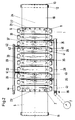
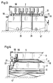
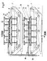
- FIGS. 8 to 16 and 19 A particularly preferred embodiment of the device 1 is described below with reference to FIGS. 8 to 16 and 19 and further below with reference to FIGS. 17 and 18.
- the embodiment illustrated in these drawing figures is identical in terms of the essential components and the basic operation of the embodiment described with reference to FIGS. 1 to 7, so that due to the use of the same reference numerals for the same or equivalent parts with regard to these details to the above description can be referred.
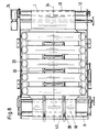
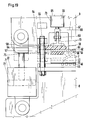
- FIGS. 9 and 19 With regard to the design of the guide at the edges of the mud chamber 2, reference is first made to FIGS. 9 and 19.
- guides are generally designated 54 for the movable pressure plates 9 and the sealing strips 21, which guide the vertical movement of the pressure membrane 6 designed as a rubber cover 26 and the vertical movement of the movable pressure plates 9.
- the guides 54 for the movable pressure plates 9 and the sealing strips 21 are designed as common guides since the movement of the pressure plates 9 and the sealing strips 21 takes place in the same direction.
- the guides 54 consist of upstanding pins 55 and 56, which are fastened in pairs to each end of one of the pressure plates 8 or 9 and which slide in guide bores 57 of the sealing strips 21 and guide bores 58 in the respective other pressure plate 8 or 9.
- the pins 55 and 56 are fastened to the lower fixed pressure plates and the guide bores 58 are formed in the upper movable pressure plates 9.
- a number of guides 54 which likewise consist of the pairs of pins 55 and 56, are likewise provided on the two end faces of the mud chamber 2 at the same regular intervals.
- the sealing strips 21 are designed in such a way that the sliding in the vertical direction is improved in order to improve the guidance.
- the sealing strips 21 consist of a rigid stiffening strip 59 made of plastic or the like.
- the stiffening strip 59 can either be designed as a frame surrounding the pressure membrane 6 or can consist of several individual parts.
- the sealing strips 21 consist of a sealing body 60 which runs around the circumference of the pressure membrane 6 and is made of a flexible material, the stiffening strip 59 on the top 61 of the edge region 2 of the pressure membrane 6 and the sealing body 60 of the stiffening strip 59 opposite on the underside 63 of the edge region 62 the pressure membrane 6 is attached.
- the stiffening strip 59 is glued or welded to the top of the rubber cover 26 forming the pressure membrane 6, while the sealing body 60 is welded or supported by the opposite stiffening strip 59 on the opposite side of the rubber cover 26, ie facing the filter surface 5 is glued.
- the sealing strip 21 is formed with an edge 64 which projects beyond the circumference of the pressure membrane 6 and in which the guide bores 57 are arranged.
- a reinforcement 75 is provided on the underside of the projecting edge 64, so that the upward and downward movement of the edge region 62 of the pressure membrane 6 described in more detail below leads to the guide on the pin 55, 56 in the manner of a this sliding plastic bushing, which consists of the material of the stiffening strip 59 and the reinforcement 75.
- FIGS. 8 to 19 The further essential feature of the embodiment described with reference to FIGS. 8 to 19, which differs from the embodiment according to FIGS. 1 to 7, namely the separate drive 73 for the sealing strips 21, is described with particular reference to FIGS. 9 to 16 and 19 described in more detail.
- a separate drive, generally designated 73, is provided for the sealing strips 21, by means of which the sealing strips 21 can be moved up and down in a positively controlled manner.
- the drive 73 is formed by a number of pressure generators 65 arranged and controllable on the sealing strips 21, which, as shown in particular in FIG. 9, are distributed at regular intervals around the circumference of the pressure membrane 6 above the sealing strips 21.
- the pressure generators 65 enable the sealing strips 21 to face the upper pressure plate 9, i.e. regardless of their movement in the direction of the filter belt 10 and can be lifted off this.
- the pressure generators 65 are designed as pneumatic cylinders 66, which can be actuated to open and close the sludge chamber 2 by raising and lowering the sealing strips 21.
- the pneumatic cylinders are supported on the upper pressure plates 9 and move together with them.
- the arrangement is such that compression of the air remaining in the individual pneumatic cylinders 66 after lowering the sealing strips 21 onto the filter belt 10 increases the sealing pressure during the pressure stroke of the upper pressure plates 9. Consequently, when the pressure in the sludge chamber 2 increases, the pressure at which it is sealed is increased at the same time.
- two pneumatic cylinders 66 are provided at each end of an upper pressure plate 9, a corresponding number of pneumatic cylinders 66 being provided at regular intervals over their length on the two pressure plates 9, which form the end faces of the mud chamber 2.
- the piston rods 67 of the pneumatic cylinder 66 are connected in an articulated manner to the stiffening strip 59 of the sealing strip by a fork 68 being arranged at the free end of the piston rod 67 of each pneumatic cylinder 66, which fork is upright via a pivot pin 69 and corresponding bores standing leg of a T-piece 70 which is attached to the top of the reinforcing bar 59.
- the arrangement is such that the piston rod 67 coincides with the center line of the sealing body 60, so that an optimal pressure distribution is achieved when the sealing body 60 is pressed together.
- the sealing strip 21 can therefore be moved up and down independently of the upper pressure plate 9, the lowered position in which the sludge chamber 2 is sealed being illustrated in broken lines in FIG. 19. Because of this arrangement, on the one hand, compared to the first exemplary embodiment, the hydraulic pressure generators only have to carry out half the lifting height, since, as can be seen from FIG. 19, the rubber cover 26 of the pressure membrane 6 moves into a completely straight position via the pneumatic cylinders 66 will can. Furthermore, compared with the first exemplary embodiment, it is achieved that a separate locking cylinder is not required in the context of the hydraulic high-pressure generators 22, so that the hydraulic high-pressure generators, as illustrated in FIG. 19, can be designed as single cylinders 71, which only have an upward and downward moving plunger 72 included.
- the sludge chamber 2 is empty, i.e. that a fresh section of the filter belt 10 has been inserted into the sludge chamber.
- the pneumatic cylinders 66 are first pressurized with compressed air, so that the sealing strips 21 are brought into sealing engagement with the filter belt 10 and the sludge chamber 2 is sealed on all sides.
- the sludge to be dewatered is then fed in by means of the pump 7 via the collecting line 36 through the sludge inlets 33, the sludge being fed in for better distribution through the four sludge inlets 33 shown in FIG. 9.
- this process is continued, for example, up to a pressure of 7 bar generated hydrostatically by the pump 7, whereupon a dewatering sludge 48 which can be pressed was produced by the dewatering which ensues.
- a dewatering sludge 48 which can be pressed was produced by the dewatering which ensues.
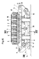
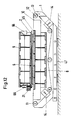
- the state of the feed and the generation of the hydrostatic pressure is illustrated in FIGS. 11 and 14.
- the pressure pistons 72 are first relieved and at the same time the pneumatic cylinders 66 are retracted, so that the pressure membrane assumes a flat shape, as is illustrated in FIG. 16.
- the discharge of the sludge cake 48 can now begin with a slight opening of the gap between the pressure plate pairs 8 and 9. This state is illustrated in FIGS. 12 and 16.
- the filter belt is moved via its drive 74, so that the Sludge cake 48 is moved out of the sludge chamber 2 and is discharged at the discharge 13.
- a fresh section of the filter belt 10 is moved into the sludge chamber 2 so that the process can be repeated.
- this embodiment according to the embodiment according to FIGS. 5 to 7 consists of two superposed devices 1, which can be operated in the same way as the previously described embodiment, so that an almost continuous operation is possible.
- a control is also preferably used here, which controls the cyclical operation of the shut-off valves 38, the closing valves 37, the high-pressure generator 22, the pneumatic cylinder 66 and the drive 74 of the filter belt 10 in accordance with the operating cycle of the two devices.
- the device according to the invention can be operated either as a single unit discontinuously or continuously in the manner described.
Landscapes
- Chemical & Material Sciences (AREA)
- Chemical Kinetics & Catalysis (AREA)
- Engineering & Computer Science (AREA)
- Mechanical Engineering (AREA)
- Filtration Of Liquid (AREA)
- Treatment Of Sludge (AREA)
- Separation Using Semi-Permeable Membranes (AREA)
- Bending Of Plates, Rods, And Pipes (AREA)
- Organic Low-Molecular-Weight Compounds And Preparation Thereof (AREA)
- Materials For Medical Uses (AREA)
- Water Treatment By Sorption (AREA)
Claims (21)
- Procédé de déshydratation de boue et de substances similaires, dans lequel la boue est envoyée sous pression, par une pompe, dans au moins une chambre à boue fermée, comportant des surfaces de filtration, et une pression hydrostatique provoquant la déshydratation est constituée dans la chambre à boue, dans lequel, après obtention d'un niveau de pression à définir, la chambre à boue est séparée de la pompe et le volume de la chambre à boue est ensuite réduit et une pression de déshydratation mécanique est produite, laquelle est supérieure à la pression hydrostatique obtenue et dans lequel, pour évacuer le gâteau de filtre réalisé, la surface de filtration est enlevée avec le gâteau de filtre de la chambre à boue, caractérisé en ce que plusieurs chambres à boue fonctionnent en alternance et en cadence, tandis que la pompe, produisant la pression hydrostatique, est entraînée en continu, en ce qu'au moins une chambre à boue est alimentée par la pompe jusqu'à obtention du niveau de pression à définir, en ce qu'ensuite l'alimentation pour la pompe est commutée sur au moins une deuxième des chambres à boue, en ce que pendant l'établissement de la pression de déshydratation hydrostatique dans la deuxième chambre à boue, la déshydratation mécanique supplémentaire est réalisée dans la première chambre à boue, en ce qu'à l'obtention du niveau à définir de la pression hydrostatique dans la deuxième chambre à boue, l'alimentation par la pompe est commutée sur au moins une troisième des chambres à boue, en ce que pendant l'établissement de la pression de déshydratation hydrostatique dans la troisième chambre à boue, la déshydratation mécanique supplémentaire est réalisée dans la deuxième chambre à boue et en même temps le gâteau de filtre est extrait de la première des chambres à boue, en ce que l'arrivée de la boue et l'extraction du gâteau de filtre s'effectuent pratiquement en continu, mais à partir de différentes chambres à boue.
- Procédé selon la revendication 1, caractérisé en ce que la boue et simultanément envoyée par la pompe dans chacune des chambres à boue, à partir de plusieurs points.
- Dispositif pour la mise en oeuvre du procédé selon les revendications 1 ou 2, comportant une chambre à boue (2) fermée de tous côtés, qui présente des surfaces de filtration (5) et une entrée de boue (33), laquelle est reliée, par un conduit, à une pompe (7) produisant la pression de filtration, les surfaces de filtration (5) de la chambre à boue (2) étant situées entre des plaques de pression fixes et des plaques de pression mobiles et étant alimentées mécaniquement en pression, après mise hors service de la pompe, et dans lequel la chambre à boue comporte un couvercle (3), contenant les plaques de pression (9) mobiles et un fond (4) contenant les plaques de pression (8) fixes, caractérisé en ce qu'il est prévu au moins trois chambres à boue (2) parallèles entre elles, en ce que les entrées de boue (33) des chambres à boue (2) sont raccordées, par des vannes de fermeture (37) à un collecteur (36), en ce que le collecteur (36) comporte des vannes d'arrêt (38), en ce que les collecteurs (36) des chambres à boue (2) sont raccordés à un conduit principal (50), en ce que le conduit principal (50) est soumis en continu à la pression de la pompe (7), et en ce qu'il est prévu une commande (51) qui commande les vannes d'arrêt (38), les vannes de fermeture (37), les générateurs de haute pression (22) et l'entraînement des surfaces de filtration (5) à la cadence de travail des différentes chambres à boue (2), de manière que l'arrivée de boue et l'extraction du gâteau de filtre s'effectuent pratiquement en continu, mais à partir de différentes chambres à boue (2).
- Dispositif selon la revendication 3, caractérisé en ce que la chambre à boue (2) est constituée des surfaces de filtration (5), sous la forme d'une bande de filtration (10) circulant horizontalement et en ligne droite, par intermittence, ainsi que d'une membrane de pression (6), en ce que la membrane de pression (6) est pourvue tout autour de baguettes d'étanchéité (21), qui s'appliquent de manière étanche contre la bande de filtration (10), en position fermée, et en ce que pour les plaques de pression (9) mobiles et les baguettes d'étanchéité (21) il est prévu des organes de guidage pour le déplacement vertical.
- Dispositif selon les revendications 3 ou 4, caractérisé en ce que le couvercle (3) est déplaçable au moyen des plaques de pression (9) mobiles par rapport au fond (4) entre une position fermée et une position ouverte.
- Dispositif selon les revendications 4 ou 5, caractérisé en ce que les organes de guidage (54) des plaques de pression (9) mobiles et des baguettes d'étanchéité (21) sont conçus à la manière d'organes de guidage communs, en ce que les organes de guidage (54) se présentent sous la forme de tiges (55, 56) verticales placées sur l'une des plaques de pression (8 ou 9) d'une paire de plaques de pression, qui glissent dans des trous de guidage (57, 58) des baguettes d'étanchéité (21) et de l'autre plaque de pression (9 ou 8).
- Dispositif selon la revendication 6, caractérisé en ce que les baguettes d'étanchéité (21) sont constituées d'une baguette de renfort (59) rigide et d'un corps d'étanchéité (60), en matériau flexible, entourant le pourtour de la membrane de pression (6), en ce que la baguette de renfort (59) est fixée sur la face supérieure (61) de la zone de bordure (62) de la membrane de pression (6) et le corps d'étanchéité (60), faisant face à la baguette de renfort (59), est fixé sur la face inférieure (63) de la zone de bordure (62), en ce que la baguette d'étanchéité (21) présente un bord (64) dépassant du pourtour de la membrane de pression (6) et en ce que les trous de guidage (57) sont réalisés dans le bord (64).
- Dispositif selon l'une des revendications 3 à 7, caractérisé en ce qu'il est prévu un grand nombre de paires de plaques de pression (8, 9) juxtaposées, en ce que les plaques de pression (8) inférieures sont montées rigidement et en ce que les plaques de pression (9) supérieures sont ajustables, par des générateurs de haute pression (22) hydrauliques, contre les plaques de pression (8) inférieures ou inversement.
- Dispositif selon l'une des revendications 4 à 8 précédentes caractérisé en ce que la membrane de pression (6) est reliée, au moins dans une zone centrale (23), avec les plaques de pression (9) mobiles, en ce que sur la surface de contact (24) entre les baguettes d'étanchéité (21) et la bande de filtration (10), il est prévu des pièces d'usure (25) interchangeables, et en ce que la membrane de pression (6) est réalisée sous la forme d'une couverture en caoutchouc (26), assemblée aux baguettes d'étanchéité (21).
- Dispositif selon l'une des revendications 4 à 9, caractérisé en ce que les baguettes d'étanchéité (21), commandées positivement par un mécanisme d'entraînement (73), peuvent monter et descendre, et en ce que le mécanisme d'entraînement (73) est formé par un certain nombre de générateurs de pression (65) commandés, placés sur les baguettes d'étanchéité (21), lesquels générateurs de pression pressent les baguettes d'étanchéité (21), par rapport à la plaque de pression (9) supérieure, au choix en direction de la bande de filtration (10) et les soulèvent de celle-ci.
- Dispositif selon la revendication 10, caractérisé en ce que les générateurs de pression (65) sont des vérins pneumatiques (66), qui peuvent être actionnés en vue de l'ouverture et de la fermeture de la chambre à boue (2), par relevage et abaissement des baguettes d'étanchéité (21), en ce que les vérins pneumatiques prennent appui contre les plaques de pression (9) supérieures de manière que par compression de l'air se trouvant dans les vérins pneumatiques (66), lors de la course de pression des plaques de pression (9) supérieures, la pression d'étanchéité soit accrue, en ce qu'à chaque extrémité d'une plaque de pression (9) supérieure sont prévus deux vérins pneumatiques (66) et en ce que sur les plaques de pression (9), prévues sur les côtés frontaux de la chambre à boue (2), un certain nombre de vérins pneumatiques (66) sont répartis sur sa longueur.
- Dispositif selon la revendication 11, caractérisé en ce que les tiges de piston (67) des vérins pneumatiques (66) sont reliées de manière articulée avec la baguette de renfort (59) de la baguette d'étanchéité (21) et en ce que la liaison des tiges de piston (67) avec la baguette de renfort (59) se trouve face à la ligne centrale du corps d'étanchéité (60).
- Dispositif selon l'une des revendications 3 et 11, caractérisé en ce que la commande (51) commande les vérins pneumatiques (66), à la cadence de travail des différentes chambres à boue (2).
- Dispositif selon l'une des revendications 10 à 13, caractérisé en ce que les générateurs de haute pression (22) hydrauliques sont des vérins simples (71) avec un piston de pression (72).
- Dispositif selon l'une des revendications 4 à 14, caractérisé en ce que les baguettes d'étanchéité (21) sont précontraintes par un ressort en direction de la bande de filtration (10) et en ce que les ressorts (27), agissant sur les baguettes d'étanchéité (21), prennent appui contre les plaques de pression (9) mobiles, de manière que pendant la course de pression, la pression d'étanchéité soit en même temps accrue.
- Dispositif selon l'une des revendications 3 à 15, caractérisé en ce que les générateurs de haute pression (22) hydrauliques relient les plaques de pression (8) fixes avec les plaques de pression (9) mobiles pour former un cadre (52) fermé.
- Dispositif selon les revendications 14 ou 15, caractérisé en ce que les générateurs de haute pression (22) hydrauliques sont des doubles cylindres (28) contenant deux pistons (29, 31) et en ce que dans chaque double cylindre (28) un piston (29) est un piston de pression et le second piston (31) est un piston de fermeture.
- Dispositif selon l'une des revendications 3 à 17, caractérisé en ce que la chambre à boue (2) comporte plusieurs entrées de boue (33).
- Dispositif selon la revendication 18, caractérisé en ce que les entrées de boue (33) sont prévues dans l'axe central (34) de la membrane de pression (6) et en ce que les entrées de boue (33) sont reliées chacune par une conduite de liaison (35) avec le collecteur (36).
- Dispositif selon l'une des revendications 4 à 19 précédentes, caractérisé en ce que dans la membrane de pression (6) sont réalisées plusieurs sorties (41), commandées par des vannes (40), d'une conduite (39) pour un produit de lavage ou de nettoyage.
- Dispositif selon l'une des revendications 4 à 20, caractérisé en ce que dans la chambre à boue (2) il est prévu, entre la bande de filtration (10) et les plaques de pression (8) inférieures, une plaque (45) avec canaux de filtrat (46) ouverts vers le haut, et en ce que la plaque (45) est réalisée dans une matière plastique présentant un faible coefficient de friction.
Applications Claiming Priority (4)
| Application Number | Priority Date | Filing Date | Title |
|---|---|---|---|
| DE3915298 | 1989-05-10 | ||
| DE3915298 | 1989-05-10 | ||
| DE4011776 | 1990-04-11 | ||
| DE4011776A DE4011776C2 (de) | 1989-05-10 | 1990-04-11 | Verfahren und Kammerfilterpresse zum Entwässern von Schlämmen und ähnlichen Substanzen |
Publications (3)
| Publication Number | Publication Date |
|---|---|
| EP0397082A2 EP0397082A2 (fr) | 1990-11-14 |
| EP0397082A3 EP0397082A3 (fr) | 1991-04-03 |
| EP0397082B1 true EP0397082B1 (fr) | 1994-09-21 |
Family
ID=25880746
Family Applications (1)
| Application Number | Title | Priority Date | Filing Date |
|---|---|---|---|
| EP90108565A Expired - Lifetime EP0397082B1 (fr) | 1989-05-10 | 1990-05-07 | Procédé et dispositif pour la déshydratation de boues et de produits analoques |
Country Status (6)
| Country | Link |
|---|---|
| US (1) | US5051194A (fr) |
| EP (1) | EP0397082B1 (fr) |
| JP (1) | JPH0316609A (fr) |
| AT (1) | ATE111762T1 (fr) |
| FI (1) | FI902311A7 (fr) |
| NO (1) | NO901889L (fr) |
Cited By (1)
| Publication number | Priority date | Publication date | Assignee | Title |
|---|---|---|---|---|
| CN111991861A (zh) * | 2020-08-31 | 2020-11-27 | 上海塑茜劳防用品有限公司 | 一种附着于压滤机的淤泥块清除外加设备 |
Families Citing this family (18)
| Publication number | Priority date | Publication date | Assignee | Title |
|---|---|---|---|---|
| DE4013786A1 (de) * | 1990-04-28 | 1991-11-07 | Siempelkamp Gmbh & Co | Verfahren zum entwaessern eines schlammvolumens und trennstraenge fuer die durchfuehrung des verfahrens |
| US5355594A (en) * | 1992-12-21 | 1994-10-18 | Daekyoo Hwang | Evaporative sludge stabilization |
| DE4425451A1 (de) * | 1994-07-19 | 1996-01-25 | Kloeckner Humboldt Deutz Ag | Verfahren und Vorrichtung zum Austragen von feucht/rieselfähigem bis pastösem Material aus einem Druckfilter |
| ATE178499T1 (de) * | 1994-12-01 | 1999-04-15 | Albert Baehr | Verfahren und vorrichtung zum entwässern von schlämmen und ähnlichen substanzen |
| US5624549A (en) * | 1995-06-12 | 1997-04-29 | Muller Umwelttechnik Gmbh & Co. Kg | Apparatus for partial dewatering of raw sludge comprising reciprocating plunger presses |
| US5900139A (en) * | 1997-03-14 | 1999-05-04 | Maschinenfabrik J. Dieffenbacher Gmbh & Co. | Filter press for reducing the water content of solid materials and/or sludges |
| GR1003237B (el) * | 1998-06-23 | 1999-10-15 | Μηχανημα εκθλιψης ελαιοκαρπου | |
| DE19927267A1 (de) * | 1999-06-15 | 2000-12-28 | Handtmann Albert Entwicklung | Filtervorrichtung zum Filtrieren von Fluiden |
| AU3338101A (en) * | 2000-04-09 | 2001-10-11 | Maschinenfabrik J. Dieffenbacher Gmbh & Co. | Method and plant to reduce the water contents bound in the capillaries of fibrous cells |
| US8211319B2 (en) * | 2003-09-16 | 2012-07-03 | Bp Corporation North America Inc. | Solid-liquid separation process |
| US7812206B2 (en) | 2006-03-21 | 2010-10-12 | Bp Corporation North America Inc. | Apparatus and process for the separation of solids and liquids |
| US8530716B2 (en) * | 2008-08-14 | 2013-09-10 | Bp Corporation North America Inc. | Melt-crystallization separation and purification process |
| ES2388520B1 (es) * | 2010-02-02 | 2013-09-24 | Mª Maravillas BONO SIMO | Procedimiento e instalación para la deshidratación de lodos. |
| US20160137521A1 (en) * | 2014-11-15 | 2016-05-19 | Sesa Sterlite Limited | Method and system for extracting red-mud lumps from slurry |
| CN109432841B (zh) * | 2018-12-06 | 2019-06-21 | 浙江核星机械制造有限公司 | 一种带真空抽滤式压滤机 |
| BR102019026860A2 (pt) | 2019-12-16 | 2021-06-22 | José Oswaldo Da Silva | Equipamento e método para o desaguamento e compactação de lodos, rejeitos, materiais pastosos e suspensões |
| KR102795458B1 (ko) * | 2020-09-25 | 2025-04-11 | 주식회사 엘지화학 | 압축식 탈수기 |
| CN118079515B (zh) * | 2024-04-25 | 2024-09-13 | 佛山四合科技有限公司 | 浆料浓缩结构 |
Family Cites Families (6)
| Publication number | Priority date | Publication date | Assignee | Title |
|---|---|---|---|---|
| US3073238A (en) * | 1958-08-26 | 1963-01-15 | Macchine Per L Ind Dolciaria C | Hydraulic horizontal press with two series of multiple chambers for pressing with filter plates for very high production |
| DE1188556B (de) * | 1958-08-26 | 1965-03-11 | Macchine Per L Ind Dolciaria C | Filterpressenkammer |
| CS195320B2 (en) * | 1975-12-23 | 1980-01-31 | Aktieselskabat De Danske Sukke | Dewatering concentrated sludges and device for making this process |
| FR2374937A1 (fr) * | 1976-12-21 | 1978-07-21 | Lautrette Jean Claude | Procede et appareil de filtration continue d'une masse impregnee de liquide |
| US4639312A (en) * | 1985-10-03 | 1987-01-27 | Texaco Inc. | Filter press flow control system for dewatering sludge |
| WO1987002908A1 (fr) * | 1985-11-14 | 1987-05-21 | Hakü Hans Kübler Gmbh Filteranlagen Und Maschinenb | Filtre-presse pour separer les liquides des boues pour obtenir une teneur elevee en solides |
-
1990
- 1990-04-27 NO NO90901889A patent/NO901889L/no unknown
- 1990-05-07 EP EP90108565A patent/EP0397082B1/fr not_active Expired - Lifetime
- 1990-05-07 AT AT90108565T patent/ATE111762T1/de not_active IP Right Cessation
- 1990-05-08 FI FI902311A patent/FI902311A7/fi not_active IP Right Cessation
- 1990-05-08 US US07/520,896 patent/US5051194A/en not_active Expired - Fee Related
- 1990-05-10 JP JP2118850A patent/JPH0316609A/ja active Pending
Cited By (1)
| Publication number | Priority date | Publication date | Assignee | Title |
|---|---|---|---|---|
| CN111991861A (zh) * | 2020-08-31 | 2020-11-27 | 上海塑茜劳防用品有限公司 | 一种附着于压滤机的淤泥块清除外加设备 |
Also Published As
| Publication number | Publication date |
|---|---|
| US5051194A (en) | 1991-09-24 |
| FI902311A0 (fi) | 1990-05-08 |
| JPH0316609A (ja) | 1991-01-24 |
| NO901889L (no) | 1990-11-12 |
| EP0397082A3 (fr) | 1991-04-03 |
| ATE111762T1 (de) | 1994-10-15 |
| NO901889D0 (no) | 1990-04-27 |
| FI902311A7 (fi) | 1990-11-11 |
| EP0397082A2 (fr) | 1990-11-14 |
Similar Documents
| Publication | Publication Date | Title |
|---|---|---|
| EP0397082B1 (fr) | Procédé et dispositif pour la déshydratation de boues et de produits analoques | |
| EP0827767B1 (fr) | Dispositif de déshydratation de boues et substances similaires | |
| EP2165746B1 (fr) | Procédé et dispositif de séparation solide-liquide de mélanges de matière et suspensions | |
| EP0714687B1 (fr) | Procédé et appareil de déshydratation de bones et autres | |
| EP0295472A2 (fr) | Procédé et dispositif pour le serrage de matière de moulage dans une machine à mouler pour fonderie | |
| EP0264899B1 (fr) | Dispositif de déshydratation de boues et de matières similaires | |
| DE4011776C2 (de) | Verfahren und Kammerfilterpresse zum Entwässern von Schlämmen und ähnlichen Substanzen | |
| EP0060420A1 (fr) | Procédé et dispositif pour l'extraction de liquide de textiles, toisons, feutres, peaux et autres matières contenant de l'eau, en particulier pour l'essorage de paquets de linge | |
| DD252766A5 (de) | Filterpresse | |
| DE4320860C2 (de) | Presse zum Vakuum-Formen von Platten oder Blöcken aus körnigem Stein- oder Keramikmaterial | |
| DE3622103A1 (de) | Scheiben - membran - pressfilter | |
| EP0227084A1 (fr) | Filtre-presse | |
| DE2702612A1 (de) | Verfahren und vorrichtung zur entfernung von feuchtigkeit aus schlamm, abwasser o.dgl. mittels einer filterpresse | |
| DE19727762C2 (de) | Vorrichtung zum Entwässern von Schlamm und ähnlichen Substanzen | |
| EP0463292B1 (fr) | Procédé pour la déshydratation sous pression de boues aqueuses | |
| DE4223022A1 (de) | Vorrichtung zum Entwässern von Schlamm und ähnlichen Substanzen | |
| DE19539484C2 (de) | Verfahren und Vorrichtung zum Entwässern von Schlämmen und ähnlichen Substanzen | |
| DE2142722A1 (de) | Pump- und Förderapparat für dichte Flüssigkeitsmischungen, wie Beton oder dgl | |
| AT225720B (de) | Vorrichtung und Verfahren zum Auspressen von Flüssigkeit aus flüssigkeitshaltigem, feinkörnigem Gut, wie Kohlenschlamm u. dgl. | |
| DE3729250A1 (de) | Verfahren und vorrichtung zum entwaessern eines filterkuchens | |
| DE166150C (fr) | ||
| DE160853C (fr) | ||
| AT246630B (de) | Maschine zur Herstellung von Asbestzementplatten | |
| CH541416A (de) | Presse | |
| DE624409C (de) | Vorrichtung zur Herstellung von tafelartigen Werkstuecken aus Faserstoffbrei |
Legal Events
| Date | Code | Title | Description |
|---|---|---|---|
| PUAI | Public reference made under article 153(3) epc to a published international application that has entered the european phase |
Free format text: ORIGINAL CODE: 0009012 |
|
| AK | Designated contracting states |
Kind code of ref document: A2 Designated state(s): AT BE CH DK ES FR GB GR IT LI NL SE |
|
| PUAL | Search report despatched |
Free format text: ORIGINAL CODE: 0009013 |
|
| AK | Designated contracting states |
Kind code of ref document: A3 Designated state(s): AT BE CH DK ES FR GB GR IT LI NL SE |
|
| 17P | Request for examination filed |
Effective date: 19910928 |
|
| 17Q | First examination report despatched |
Effective date: 19920824 |
|
| GRAA | (expected) grant |
Free format text: ORIGINAL CODE: 0009210 |
|
| AK | Designated contracting states |
Kind code of ref document: B1 Designated state(s): AT BE CH DK ES FR GB GR IT LI NL SE |
|
| PG25 | Lapsed in a contracting state [announced via postgrant information from national office to epo] |
Ref country code: IT Free format text: LAPSE BECAUSE OF FAILURE TO SUBMIT A TRANSLATION OF THE DESCRIPTION OR TO PAY THE FEE WITHIN THE PRE;WARNING: LAPSES OF ITALIAN PATENTS WITH EFFECTIVE DATE BEFORE 2007 MAY HAVE OCCURRED AT ANY TIME BEFORE 2007. THE CORRECT EFFECTIVE DATE MAY BE DIFFERENT FROM THE ONE RECORDED.SCRIBED TIME-LIMIT Effective date: 19940921 Ref country code: ES Free format text: THE PATENT HAS BEEN ANNULLED BY A DECISION OF A NATIONAL AUTHORITY Effective date: 19940921 Ref country code: GB Effective date: 19940921 Ref country code: GR Free format text: LAPSE BECAUSE OF FAILURE TO SUBMIT A TRANSLATION OF THE DESCRIPTION OR TO PAY THE FEE WITHIN THE PRESCRIBED TIME-LIMIT Effective date: 19940921 Ref country code: DK Effective date: 19940921 Ref country code: NL Effective date: 19940921 Ref country code: BE Effective date: 19940921 Ref country code: FR Effective date: 19940921 |
|
| REF | Corresponds to: |
Ref document number: 111762 Country of ref document: AT Date of ref document: 19941015 Kind code of ref document: T |
|
| PG25 | Lapsed in a contracting state [announced via postgrant information from national office to epo] |
Ref country code: SE Effective date: 19941221 |
|
| EN | Fr: translation not filed | ||
| NLV1 | Nl: lapsed or annulled due to failure to fulfill the requirements of art. 29p and 29m of the patents act | ||
| GBV | Gb: ep patent (uk) treated as always having been void in accordance with gb section 77(7)/1977 [no translation filed] |
Effective date: 19940921 |
|
| PG25 | Lapsed in a contracting state [announced via postgrant information from national office to epo] |
Ref country code: LI Effective date: 19950531 Ref country code: CH Effective date: 19950531 |
|
| PGFP | Annual fee paid to national office [announced via postgrant information from national office to epo] |
Ref country code: AT Payment date: 19950531 Year of fee payment: 6 |
|
| PLBE | No opposition filed within time limit |
Free format text: ORIGINAL CODE: 0009261 |
|
| STAA | Information on the status of an ep patent application or granted ep patent |
Free format text: STATUS: NO OPPOSITION FILED WITHIN TIME LIMIT |
|
| 26N | No opposition filed | ||
| REG | Reference to a national code |
Ref country code: CH Ref legal event code: PL |
|
| PG25 | Lapsed in a contracting state [announced via postgrant information from national office to epo] |
Ref country code: AT Effective date: 19960507 |