EP0174090B1 - Diskriminierung von elektrischen Signalen - Google Patents
Diskriminierung von elektrischen Signalen Download PDFInfo
- Publication number
- EP0174090B1 EP0174090B1 EP85305441A EP85305441A EP0174090B1 EP 0174090 B1 EP0174090 B1 EP 0174090B1 EP 85305441 A EP85305441 A EP 85305441A EP 85305441 A EP85305441 A EP 85305441A EP 0174090 B1 EP0174090 B1 EP 0174090B1
- Authority
- EP
- European Patent Office
- Prior art keywords
- transducer
- response
- data
- threshold values
- signal
- Prior art date
- Legal status (The legal status is an assumption and is not a legal conclusion. Google has not performed a legal analysis and makes no representation as to the accuracy of the status listed.)
- Expired
Links
- 230000004044 response Effects 0.000 claims description 60
- 238000000034 method Methods 0.000 claims description 24
- 230000000694 effects Effects 0.000 claims description 8
- 238000012545 processing Methods 0.000 claims description 7
- 238000012544 monitoring process Methods 0.000 claims description 4
- 230000000875 corresponding effect Effects 0.000 claims 6
- 230000005540 biological transmission Effects 0.000 claims 1
- 230000002596 correlated effect Effects 0.000 claims 1
- 238000002592 echocardiography Methods 0.000 description 13
- 238000004088 simulation Methods 0.000 description 10
- 238000013459 approach Methods 0.000 description 2
- 230000003750 conditioning effect Effects 0.000 description 2
- 238000009795 derivation Methods 0.000 description 2
- 238000001514 detection method Methods 0.000 description 2
- 238000010304 firing Methods 0.000 description 2
- DGAQECJNVWCQMB-PUAWFVPOSA-M Ilexoside XXIX Chemical compound C[C@@H]1CC[C@@]2(CC[C@@]3(C(=CC[C@H]4[C@]3(CC[C@@H]5[C@@]4(CC[C@@H](C5(C)C)OS(=O)(=O)[O-])C)C)[C@@H]2[C@]1(C)O)C)C(=O)O[C@H]6[C@@H]([C@H]([C@@H]([C@H](O6)CO)O)O)O.[Na+] DGAQECJNVWCQMB-PUAWFVPOSA-M 0.000 description 1
- 238000006243 chemical reaction Methods 0.000 description 1
- 238000007796 conventional method Methods 0.000 description 1
- 238000013461 design Methods 0.000 description 1
- 238000010586 diagram Methods 0.000 description 1
- 238000003384 imaging method Methods 0.000 description 1
- 229910001338 liquidmetal Inorganic materials 0.000 description 1
- 230000035945 sensitivity Effects 0.000 description 1
- 229910052708 sodium Inorganic materials 0.000 description 1
- 239000011734 sodium Substances 0.000 description 1
Images



Classifications
-
- G—PHYSICS
- G01—MEASURING; TESTING
- G01S—RADIO DIRECTION-FINDING; RADIO NAVIGATION; DETERMINING DISTANCE OR VELOCITY BY USE OF RADIO WAVES; LOCATING OR PRESENCE-DETECTING BY USE OF THE REFLECTION OR RERADIATION OF RADIO WAVES; ANALOGOUS ARRANGEMENTS USING OTHER WAVES
- G01S7/00—Details of systems according to groups G01S13/00, G01S15/00, G01S17/00
- G01S7/52—Details of systems according to groups G01S13/00, G01S15/00, G01S17/00 of systems according to group G01S15/00
- G01S7/52004—Means for monitoring or calibrating
-
- G—PHYSICS
- G01—MEASURING; TESTING
- G01S—RADIO DIRECTION-FINDING; RADIO NAVIGATION; DETERMINING DISTANCE OR VELOCITY BY USE OF RADIO WAVES; LOCATING OR PRESENCE-DETECTING BY USE OF THE REFLECTION OR RERADIATION OF RADIO WAVES; ANALOGOUS ARRANGEMENTS USING OTHER WAVES
- G01S7/00—Details of systems according to groups G01S13/00, G01S15/00, G01S17/00
- G01S7/52—Details of systems according to groups G01S13/00, G01S15/00, G01S17/00 of systems according to group G01S15/00
- G01S7/52017—Details of systems according to groups G01S13/00, G01S15/00, G01S17/00 of systems according to group G01S15/00 particularly adapted to short-range imaging
- G01S7/52023—Details of receivers
- G01S7/52025—Details of receivers for pulse systems
- G01S7/52026—Extracting wanted echo signals
-
- Y—GENERAL TAGGING OF NEW TECHNOLOGICAL DEVELOPMENTS; GENERAL TAGGING OF CROSS-SECTIONAL TECHNOLOGIES SPANNING OVER SEVERAL SECTIONS OF THE IPC; TECHNICAL SUBJECTS COVERED BY FORMER USPC CROSS-REFERENCE ART COLLECTIONS [XRACs] AND DIGESTS
- Y10—TECHNICAL SUBJECTS COVERED BY FORMER USPC
- Y10S—TECHNICAL SUBJECTS COVERED BY FORMER USPC CROSS-REFERENCE ART COLLECTIONS [XRACs] AND DIGESTS
- Y10S367/00—Communications, electrical: acoustic wave systems and devices
- Y10S367/90—Sonar time varied gain control systems
Definitions
- This invention relates to the processing of electrical signals so as to discriminate between signal components of interest and unwanted background signal noise.
- the invention is particularly (but not necessarily exclusively) applicable to ultrasonic pulse-echo techniques where the background noise is largely attributable to reverberation effects resulting from pulsing of the pulse transmitter coupled with the random electrical noise level of the conditioning electronics.
- the reverberation effects accompany the transmitted pulse and decay in an approximately exponential manner, being superimposed on the electrical noise level of the electronics.
- the echo pulses are likewise superimposed on the electrical noise level and are required to be distinguished from the background noise.
- the output signal is gated for a suitable interval of time during which the echo pulses are expected to be available for detection.
- Such gating will usually eliminate the larger amplitude reverberation effects as these will have decayed substantially before the commencement of the gating interval. Nevertheless, in many cases, the gating interval will embrace some of the reverberation components as well as the electrical noise component.
- One approach of achieving discrimination is to impose a fixed level threshold of suitable amplitude and, to avoid spurious signals, the threshold level must be selected to be above the largest amplitude reverberation effects that are likely to occur during the gating interval.
- the magnitude of the threshold level may result in loss of low amplitude echo signals; the threshold level may need to be modified if the gating interval is changed or shifted; useful information may be lost in case of signal components not falling within the gating interval; and the reverberation effects vary from one ultrasonic transducer to another with the consequence that the threshold levels may likewise differ for different transducers of the same design.
- the object of the present invention is to provide improvements in signal discrimination.
- a prior method/system of simulating the time-variable background signal component of the electrical response of a transducer whose response includes at least one data-providing signal superimposed on said background signal is known from document GB-A-2 007 061
- According to one aspect of the present we provide a method of simulating the time-variable background signal component of the electrical response of a transducer whose response includes at least one data-providing signal superimposed on said background signal, said background signal comprising a first decaying component attributable to reverberation of the transducer and a second ever-present electrical noise component contributed by electronics associated with the transducer, said method comprising: operating said transducer to produce a first response; initially storing in digital form a plurality of threshold values which collectively approximate the envelope of said first response; operating the transducer to produce a second response with a different data-providing signal distribution; and modifying said stored threshold values so that they collectively
- a system comprising input means for connection to or connected to a transducer producing a response which may contain at least one data-providing signal superimposed on an unwanted time-variable background signal which is independent of said data-providing signal(s), digital storage means for storing a plurality of threshold values which correspond to successive intervals of time and collectively approximate the envelope of said time-varying background signal, said stored threshold values having been derived by a method comprising: operating said transducer to produce a first response; initially storing in digital form a plurality of threshold values which collectively approximate the envelope of said first response; operating the transducer to produce a second response with a different data-providing signal distribution; and modifying said stored threshold values so that they collectively approximate an envelope corresponding to the transducer background signal component freed of the data-providing signals present in said first and second responses the method including combining said initially stored threshold values with said second response to derive an output in which the data-providing signal component(s) of said first response
- the system shown in Fig. 2 is primarily intended for use in ultrasonic imaging in liquid metal cooled fast breeder reactors wherein echos from a group of sodium immersible pulse-echo transducers are collected and stored, the transducers being pulsed sequentially as they are moved progressively over the target to be imaged. Efficient scanning of the target depends on maximising the amount of data collected in a given time.
- Figure 1A illustrates a typical transducer response obtained which consists of echos 12, 14, 16 superimposed on a background noise level comprising electrical noise produced by the electronics associated with the transducers and reverberation effects resulting from firing of the transducer.
- the electronics noise is present at all times whereas the reverberation component (which is indicated by reference numeral 18) decays substantially exponentially (with some superimposed fine structure) to the level of the electronics noise.
- the reverberation component which is indicated by reference numeral 18
- the reverberation component predominates whereas the electronics noise dominates at the right hand side.
- the signal may be gated as shown by reference numeral 21 to define the area of interest.
- a fixed threshold level may be imposed.
- the threshold level must be set slightly above the maximum amplitude peaks, eg. 22, of the background noise otherwise background peaks can be confused with echos.
- the use of a fixed level may result in loss of useful data since relatively small amplitude echos will be masked. It will be seen that during typical gating period, the background may contain a significant contribution from the decaying reverberation component.
- the drawbacks associated with the use of a fixed threshold level are largely overcome by producing a threshold trace which follows closely the variations in the background signal (reverberation plus electronics noise). Derivation of the threshold trace will be described herein below.
- the threshold trace is derived for each transducer and is stored in digital form as a large number of threshold values in assigned memory addresses of an electronic memory 30 (see Fig. 2), each threshold level being associated with a particular interval of time relative to a datum, eg. the transmitted pulse.
- the group of memory locations corresponding to a particular transducer will store a series of threshold values which, when taken in the appropriate sequence, will collectively approximate the envelope of the background characteristic of that transducer so that the real-time background can be nullified by the threshold trace.
- the circuitry comprises a central control 32 which receives, via input lines 34 and 36, the transmit signals from the transducers as they fire and data enabling the transducers to be identified.
- a central control 32 which receives, via input lines 34 and 36, the transmit signals from the transducers as they fire and data enabling the transducers to be identified.
- certain memory locations are reserved in the memory 30 for each transducer and the identification signals received on input line 36 enable the control 32 to address, via 38, those memory locations associated with the respective transducer whereby the contents of those memory locations can be loaded into an up/down counter 40 via input/output device 42.
- Line 44 from the control 32 allows counting pulses to be applied to the counter for the purposes explained below.
- the input/output device 42 is also connected to a level shift amplifier 46 via D/A converter 48 whereby the signal level of the amplifier may be shifted in dependence upon the analogue counterparts of the digital signals obtained from the memory 30.
- the transducer signals are applied to the amplifier 46 via input line 49 and the output 50 of amplifier is connected to a pair of discriminators 52, 54.
- the discriminator 54 serves to detect echos which are supplied to echo-processing circuitry via output line 56 for analysis using conventional techniques whereby, for instance, the time intervals elapsing between echo signals and a datum signal (eg. the transmitted signal) can be determined.
- the discriminator 52 is connected to the counter 40 via line 58 and determines the direction of counting according to whether the output on line 50 is greater or smaller than a reference signal (which may be produced by the control 32) applied to input 60 of the discriminator 52.
- the memory locations associated with each transducer will store a large number of digital values which can be applied sequentially via the D/A converter 48 to the level shifting input of the amplifier 46 so that level of the latter is continually varied in dependence upon the contribution made by the background component of its signal trace.
- the background component is effectively nullified so as to leave only the data-providing signal, ie. the echos, which can then be supplied to the echo processing circuitry via discriminator 54.
- the calibration procedure for one transducer will now be described.
- the signal trace of the transducer is as shown in Fig. 1A which has been described earlier.
- the first stage in the calibration procedure involves storing, in an assigned area of memory 30, a digital simulation of the transducer trace shown in Fig. 1A. It will be understood that each time the transducer is fired, it will generate the same trace provided all other factors, eg. transducer position etc., remain unchanged. Initially, the contents of the memory 30 will all be zero or some other arbitary value.
- the control 32 initiates a sequence of steps in which the contents of different addresses in the memory are loaded into the counter 40 and also into the converter 48. It will be appreciated that the time interval in which each step of the sequence is executed will be very short, ie. a few milliseconds, so that during each sequence a large number of steps will be involved.
- a predetermined reference signal is applied to the input 60 of the discriminator 52.
- Each step of the sequence involves shifting the level of the amplifier 46 according to the digital value loaded into the converter 48 and comparing the output on line 50 with the reference signal on line 60. If the comparison shows that the amplifier output exceeded the reference level, the discriminator produces a signal on line 58 which places the counter 40 in a decrement mode. If not, a signal is applied to line 58 to place the counter in an increment mode.
- a predetermined number of pulses eg. 1 is supplied to the counter 40 by the control 32 so that the counter is decremented or incremented by that number of pulses, depending on the mode signal applied via line 58. The updated contents of the counter 40 are then loaded back into the respective memory address in the memory 30.
- Figure 1B shows the compensated output on line 50 which will be seen to fluctuate to a small extent only about the reference level indicated by reference number 70.
- Figure 1C shows the simulated transducer trace provided collectively by the digital values stored in the memory 30, each digital value being shown as a dot in Figure 1C.
- the arrangement may be such that incrementing or decrementing of the contents of one address and return to memory takes place while the next address is being loaded into the converter 48.
- the decrement mode of the counter may be inhibited temporarily so that only incrementing is possible. In this way, stored digital value can be adjusted so that the compensated output on line 50 is just above the reference level 70 applied to input 60.
- the simulated trace can be seen to contain echos 12, 14, 16 as well as reverberation and electrical noise components.
- the second calibration stage involves freeing the simulation of the echo components and this is achieved by causing the transducer to produce a trace with differently positioned echos, eg. by changing the positional relationship between the transducer and a scanned target. In general, such a change will only alter the positions of the echos and the envelope of the reverberation and electrical noise components will remain substantially the same for a given transducer and associated conditioning circuitry.
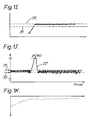
- the changes made result in the compensated output on line 50 being of the form shown in Figure 1D in which the old echos 12, 14, 16 are seen in inverted form (even though they are no longer present in the transducer trace) and a new echo 72 is superimposed on the otherwise substantially constant output.
- the procedure of the first calibration stage is repeated but with decrementing of the counter 40 disabled so that stored digital values in memory are adjusted to eliminate only the inverted echos.
- the resulting output on line 50 is indicated in Figure 1E and the corresponding digital simulation collectively represented by the stored digital values is shown in Figure 1F which, at this time, will be a close approximation to the envelope of the reverberation and electrical noise components of the transducer.
- the transmitter pulse is inhibited as a result of which the compensated output on line 50 will appear as shown in Figure 1H.
- Incrementing of the counter 40 is also inhibited and the procedure of the first stage is then repeated but with the increment inhibit imposed and a second reference level 75 applied at input 60 of the discriminator 52.
- the second reference level 75 may be selected so that it is slightly above the peaks of the reverberation dominated part of the background level.
- the resulting decrementing of the contents of the memory leads to a compensated output on line 50 of the form shown in Figure 1I and when transmitter firing is resumed, the output will be as shown in Figure 1J in which all of the background peaks are substantially masked by the second reference level 75.
- the digital simulation may be shown in Figure 1K.
- compensation of the transducer output is achieved by combining the digital simulation (following conversion to analogue form) with the transducer output by means of a level shift amplifier wherein the level shift is determined by the stored digital values.
- the digital simulation may be employed, eg. instead of modulating the level or gain shift of an amplifier, the digitally stored values may be used to modulate the discriminator 52.
Landscapes
- Engineering & Computer Science (AREA)
- Computer Networks & Wireless Communication (AREA)
- Physics & Mathematics (AREA)
- General Physics & Mathematics (AREA)
- Radar, Positioning & Navigation (AREA)
- Remote Sensing (AREA)
- Measurement Of Velocity Or Position Using Acoustic Or Ultrasonic Waves (AREA)
- Radar Systems Or Details Thereof (AREA)
Claims (12)
- Verfahren zum Simulieren der zeitveränderlichen Hintergrundsignalkomponente (19) der elektrischen Reaktion eines Wandlers, dessen Reaktion zumindest ein datenlieferndes Signal (12, 14, 16) aufweist, welches dem Hintergrundsignal (18) überlagert ist, wobei das Hintergrundsignal eine erste abnehmende Komponente aufweist, die einem Nachhall des Wandlers zuschreibbar ist, und eine zweite, ständig vorliegende elektrische Rauschkomponente aufweist, deren Beitrag von der Elektronik herrührt, die dem Wandler zugeordnet ist, mit folgenden Schritten: Betrieb des Wandlers zur Erzeugung einer ersten Reaktion; anfängliches Speichern, in digitaler Form, mehrerer Schwellenwerte, die kollektiv die Umhüllende der ersten Reaktion (Figur 1C) approximieren; Betrieb des Wandlers, um eine zweite Reaktion mit einer unterschiedlichen, datenliefernden Signalverteilung zu erzeugen; und Modifizieren der gespeicherten Schwellenwerte, so daß sie kollektiv eine Umhüllende approximieren, die der Wandlerhintergrundsignalkomponente entspricht, welche von den datenliefernden Signalen befreit wurde, die in der ersten und zweiten Reaktion vorhanden sind, wobei das Verfahren ein Kombinieren der anfänglich gespeicherten Schwellenwerte (Figur 1C) mit der zweiten Reaktion umfaßt, um ein Ausgangssignal (Figur 1D) zu erzeugen, bei welchem die datenliefernde Signalkomponente bzw. die datenliefernden Signalkomponenten der ersten Reaktion invertiert ist bzw. sind in bezug auf die datenliefernde Signalkomponente bzw. die datenliefernden Signalkomponenten der zweiten Reaktion, und das Modifizieren der Schwellenwerte umfaßt, um von dem kombinierten Ausgangssignal die datenliefernde Signalkomponente bzw. die datenliefernden Signalkomponenten zu annullieren.
- Verfahren nach Anspruch 1, bei welchem zusätzlich folgende Schritte vorgesehen sind: zeitweiliges Eliminieren der Quelle der Nachhallkomponente, so daß nur die zweite Komponente vorliegt; Kombinieren der zweiten Komponente mit den Schwellenwerten; und, wenn das kombinierte Signal innerhalb eines vorbestimmten Bereichs von einem Referenzwert liegt, Erhöhen der Größe der korrespondierenden Schwellenwerte, so daß das kombinierte Signal zu dem Referenzwert hin konvergiert, wobei die sich ergebenden Schwellenwerte daraufhin verwendet werden, um nachfolgende Wandlerreaktionen zu bearbeiten.
- Verfahren nach Anspruch 1 oder 2, bei welchem mehrere Wandler vorhanden sind, und das Verfahren auf jeden Wandler angewendet wird, um einen Satz von Schwellenwerten für jeden Wandler abzuleiten und zu speichern, und bei welchem die nachfolgende Bearbeitung jeder Wandlerreaktion den Schritt des Kombinierens der Reaktion mit dem entsprechenden Satz gespeicherter Schwellenwerte einschließt.
- Signalverarbeitungssystem mit einer Eingabeeinrichtung, die mit einem Wandler verbunden oder verbindbar ist, der eine Reaktion erzeugt, die zumindest ein datenlieferndes Signal (12, 14, 16) enthalten kann, welches einem unerwünschten, zeitveränderlichen Hintergrundsignal (18) überlagert ist, welches unabhängig von dem datenliefernden Signal bzw. den datenliefernden Signalen ist, mit einer digitalen Speichereinrichtung (30), um mehrere Schwellenwerte zu speichern, die aufeinanderfolgenden Zeitintervallen entsprechen und kollektiv die Umhüllende des zeitveränderlichen Hintergrundsignals approximieren, wobei die gespeicherten Schwellenwerte durch ein Verfahren mit folgenden Schritten abgeleitet wurden: Betreiben des Wandlers, um eine erste Reaktion zu erzeugen; anfängliches Speichern, in digitaler Form, mehrerer Schwellenwerte, die kollektiv die Umhüllende der ersten Reaktion (Figur 1C) approximieren; Betreiben des Wandlers, um eine zweite Reaktion mit einer unterschiedlichen datenliefernden Signalverteilung zu erzeugen; und Modifizieren der gespeicherten Schwellenwerte (Figur 1C), so daß diese kollektiv eine Umhüllende approximieren, die der Wandlerhintergrundsignalkomponente entspricht, die von den datenliefernden Signalen befreit ist, welche in der ersten und zweiten Reaktion vorliegen, wobei das Verfahren das Kombinieren der anfänglich gespeicherten Schwellenwerte (Figur 1C) mit der zweiten Reaktion umfaßt, um ein Ausgangssignal (Figur 1D) abzuleiten, bei welchem die datenliefernde Signalkomponente bzw. die datenliefernden Signalkomponenten der ersten Reaktion invertiert ist bzw. sind in bezug auf die datenliefernde Signalkomponente bzw. die datenliefernden Signalkomponenten der zweiten Reaktion, und das Verfahren das Modifizieren der Schwellenwerte aufweist, um die datenliefernde Signalkomponente bzw. die datenliefernden Signalkomponenten der ersten Reaktion von dem kombinierten Ausgangssignal zu annullieren, mit einer Einrichtung zum Wiedergewinnen der Schwellenwerte aus der Speichereinrichtung und zum Kombinieren jedes Schwellenwertes mit einem korrespondierenden Zeitintervallabschnitt der Wandlerreaktion, um zumindest im wesentlichen den Hintergrundsignalbeitrag zu der Wandlerreaktion während dieses Zeitintervalls zu Null zu machen, und mit einer Einrichtung zur Überwachung der Wandlerreaktion auf das Vorliegen datenliefernder Signale.
- System nach Anspruch 4, bei welchem eine Einrichtung vorgesehen ist, um selektiv die Wandlerreaktion zu takten, wodurch eine Verarbeitung wie voranstehend beschrieben auf einen vorausgewählten Abschnitt der Reaktion beschränkt werden kann, der vermutlich interessierende datenliefernde Signale aufweist.
- System nach Anspruch 4 oder 5, bei welchem die Kombiniereinrichtung während jedem der Zeitintervalle betätigbar ist, um den Signalpegel der Wandlerreaktion um einen Betrag zu verschieben, welcher auf den zugehörigen Schwellenwert bezogen ist, wodurch in Abwesenheit datenliefernder Signale die Wandlerreaktion in ein Ausgangssignal mit im wesentlichen konstanter Amplitude gewandelt wird.
- System nach Anspruch 4 oder 5, bei welchem die Kombiniereinrichtung betätigbar ist, um dadurch eine Kombination herbeizuführen, daß sie die Wandlerreaktion, die während jedem der Zeitintervalle vorherrscht, mit dem jeweiligen Schwellenwert vergleicht, und ein Ausgangssignal zur Verfügung stellt, welches ein datenlieferndes Signal anzeigt, falls die Wandlerreaktion den entsprechenden Schwellenwert um einen vorbestimmten Betrag überschreitet.
- System nach einem der Ansprüche 4 bis 7, bei welchem die Überwachungseinrichtung betätigbar ist, um die Zeit zu bestimmen, die zwischen dem Auftreten des datenliefernden Signals bzw. jedes datenliefernden Signals und einem Datumsignal vergeht.
- System nach einem der Ansprüche 4 bis 8, bei welchem die Schwellenwerte aus einer digitalen Form in eine analoge Form vor dem Kombinieren mit den jeweiligen Abschnitten der Wandlerreaktion umgewandelt werden.
- System nach einem der Ansprüche 4 bis 8, bei welchem die Abschnitte der Wandlerreaktion in digitale Form vor der Kombination mit den jeweiligen Schwellenwerten gewandelt werden.
- System nach einem der Ansprüche 4 bis 10, bei welchem die Eingabeeinrichtung mit mehreren Wandlern verbunden oder verbindbar ist, und die Speichereinrichtung einen Satz von Schwellenwerten enthält, die jedem Wandler zugeordnet sind, wobei eine Steuereinrichtung vorgesehen ist, um selektiv die Übertragung der Wandlerreaktionen zu der Kombiniereinrichtung zusammen mit den zugeordneten Schwellenwerten zu ermöglichen, wodurch die Wandlerreaktionen auf datenliefernde Signale untersucht werden können in einer vorbestimmten Sequenz.
- System nach einem der Ansprüche 4 bis 11, bei welchem eine Einrichtung zum Überwachen der Position des Wandlers oder jedes Wandlers in Beziehung auf eine vorbestimmte Datumsposition vorgesehen ist, wodurch die datenliefernden Signale mit Abtastbewegungen des Wandlers bzw. der Wandler korreliert werden können.
Applications Claiming Priority (2)
| Application Number | Priority Date | Filing Date | Title |
|---|---|---|---|
| GB848422022A GB8422022D0 (en) | 1984-08-31 | 1984-08-31 | Electrical signal discrimination |
| GB8422022 | 1984-08-31 |
Publications (3)
| Publication Number | Publication Date |
|---|---|
| EP0174090A2 EP0174090A2 (de) | 1986-03-12 |
| EP0174090A3 EP0174090A3 (en) | 1987-08-19 |
| EP0174090B1 true EP0174090B1 (de) | 1992-04-01 |
Family
ID=10566077
Family Applications (1)
| Application Number | Title | Priority Date | Filing Date |
|---|---|---|---|
| EP85305441A Expired EP0174090B1 (de) | 1984-08-31 | 1985-07-30 | Diskriminierung von elektrischen Signalen |
Country Status (5)
| Country | Link |
|---|---|
| US (1) | US4829490A (de) |
| EP (1) | EP0174090B1 (de) |
| JP (1) | JPS6171379A (de) |
| DE (1) | DE3585759D1 (de) |
| GB (1) | GB8422022D0 (de) |
Cited By (1)
| Publication number | Priority date | Publication date | Assignee | Title |
|---|---|---|---|---|
| DE102011080050A1 (de) | 2011-07-28 | 2013-01-31 | Horst Siedle Gmbh & Co. Kg | Elektrische Schaltung, insbesondere für einen Umdrehungszähler |
Families Citing this family (11)
| Publication number | Priority date | Publication date | Assignee | Title |
|---|---|---|---|---|
| US4992998A (en) * | 1986-10-03 | 1991-02-12 | Federal Industries Industrial Group Inc. | Acoustic range finding system |
| US4831565A (en) * | 1986-10-03 | 1989-05-16 | Canadian Corporate Management Company Limited | Process control equipment for adverse environments |
| US4890266A (en) * | 1987-04-22 | 1989-12-26 | Federal Industries Industrial Group Inc. | Acoustic range finding system |
| ATE92639T1 (de) * | 1988-06-13 | 1993-08-15 | Siemens Ag | Verfahren zur stoerunterdrueckung bei ultraschall- abstandsmessungen. |
| DE3822699A1 (de) * | 1988-07-05 | 1990-01-11 | Krautkraemer Gmbh | Verfahren und vorrichtung zur laufzeitmessung mittels ultraschall in fluessigen oder festen materialien nach der impuls-reflexionsmethode |
| JPH0298683A (ja) * | 1988-10-06 | 1990-04-11 | Tech Res & Dev Inst Of Japan Def Agency | 誤検出確率自動設定目標検出方式 |
| ATE93065T1 (de) * | 1988-11-15 | 1993-08-15 | Siemens Ag | Verfahren zur unterdrueckung von stoersignalen beim betrieb von ultraschall-naeherungsinitiatoren. |
| US5183048A (en) * | 1991-06-24 | 1993-02-02 | Endosonics Corporation | Method and apparatus for removing artifacts from an ultrasonically generated image of a small cavity |
| GB9919366D0 (en) * | 1999-08-16 | 1999-10-20 | Meggitt Mobrey Limited | Ultrasound level detection using a dynamic threshold |
| US7477181B2 (en) * | 2007-02-14 | 2009-01-13 | Delphi Technologies, Inc. | Method of adaptively adjusting the target detection sensitivity of a motor vehicle radar |
| DE102011102574B4 (de) * | 2011-05-26 | 2017-05-11 | Valeo Schalter Und Sensoren Gmbh | Verfahren zur Erzeugung einer Schwellwertkurve, Verfahren zur Entfernungsbestimmung und Vorrichtung zur Umfelderfassung in einem Fahrzeug |
Family Cites Families (13)
| Publication number | Priority date | Publication date | Assignee | Title |
|---|---|---|---|---|
| DE1234282B (de) * | 1961-09-04 | 1967-02-16 | Telefunken Patent | Digital-Radargeraet |
| US3505637A (en) * | 1964-03-10 | 1970-04-07 | Us Navy | Digital overflow threshold for sonar |
| US3896411A (en) * | 1974-02-19 | 1975-07-22 | Westinghouse Electric Corp | Reverberation condition adaptive sonar receiving system and method |
| US3942150A (en) * | 1974-08-12 | 1976-03-02 | The United States Of America As Represented By The Secretary Of The Navy | Correction of spatial non-uniformities in sonar, radar, and holographic acoustic imaging systems |
| US3959770A (en) * | 1974-10-21 | 1976-05-25 | Stanford Research Institute | Method and apparatus for error compensation in multichannel systems |
| US4117538A (en) * | 1977-05-04 | 1978-09-26 | Raytheon Company | Radar system with specialized weighting |
| JPS5912145B2 (ja) * | 1977-10-21 | 1984-03-21 | 古野電気株式会社 | レ−ダ−及び類似装置 |
| CA1135826A (en) * | 1978-09-08 | 1982-11-16 | Adrian Van't Hullenaar | Digital time-delay beamformer for sonar systems |
| US4401987A (en) * | 1979-04-03 | 1983-08-30 | Sonatech, Inc. | Ranging system having reduced recognition jitter |
| US4290126A (en) * | 1979-11-09 | 1981-09-15 | General Electric Company | Ultrasonic intrusion alarm system |
| US4315325A (en) * | 1980-07-02 | 1982-02-09 | Purecycle Corporation | Echo ranging pulse discrimination circuit |
| US4499564A (en) * | 1980-08-20 | 1985-02-12 | Secom Co., Ltd. | Pattern comparison ultrasonic surveillance system with noise suppression |
| US4512000A (en) * | 1980-12-23 | 1985-04-16 | Tokyo Shibaura Denki Kabushiki Kaisha | Object detector which compares returned signals from successive transmissions |
-
1984
- 1984-08-31 GB GB848422022A patent/GB8422022D0/en active Pending
-
1985
- 1985-07-30 EP EP85305441A patent/EP0174090B1/de not_active Expired
- 1985-07-30 DE DE8585305441T patent/DE3585759D1/de not_active Expired - Lifetime
- 1985-07-31 US US06/760,956 patent/US4829490A/en not_active Expired - Fee Related
- 1985-08-30 JP JP60191834A patent/JPS6171379A/ja active Pending
Cited By (1)
| Publication number | Priority date | Publication date | Assignee | Title |
|---|---|---|---|---|
| DE102011080050A1 (de) | 2011-07-28 | 2013-01-31 | Horst Siedle Gmbh & Co. Kg | Elektrische Schaltung, insbesondere für einen Umdrehungszähler |
Also Published As
| Publication number | Publication date |
|---|---|
| EP0174090A2 (de) | 1986-03-12 |
| GB8422022D0 (en) | 1984-10-24 |
| US4829490A (en) | 1989-05-09 |
| EP0174090A3 (en) | 1987-08-19 |
| JPS6171379A (ja) | 1986-04-12 |
| DE3585759D1 (de) | 1992-05-07 |
Similar Documents
| Publication | Publication Date | Title |
|---|---|---|
| EP0174090B1 (de) | Diskriminierung von elektrischen Signalen | |
| US5497661A (en) | Method of measuring the delay of ultrasound in the pulse reflection method | |
| US5822275A (en) | Method and apparatus for fixed target echo suppression in distance measurement on the principle of pulse transit time | |
| US4232380A (en) | Underwater mapping apparatus and method | |
| US5063931A (en) | Method and apparatus for signal dependent gain control | |
| US4057049A (en) | Apparatus for and methods of pulse-echo examination | |
| EP0248623B1 (de) | Ultraschall Abtastgerät | |
| US4974214A (en) | Method for the suppression of interference signals during operation of ultrasonic proximity transducers | |
| EP0393741B1 (de) | Akustisches Detektionsgerät | |
| US5036477A (en) | Method for the interference suppression in ultrasonic distance measurements | |
| US4452085A (en) | Method and means for generating time gain compensation control signal for use in ultrasonic scanner and the like | |
| JPH05196733A (ja) | 魚群探知機の単体魚判別回路 | |
| US4364114A (en) | Method and apparatus for determining the acoustic velocity of a workpiece | |
| US20020100326A1 (en) | Method and apparatus for measuring ultrasonic properties of an object | |
| JPS6161072B2 (de) | ||
| US4245332A (en) | Receiver circuit for an echo-sounding system | |
| US4581937A (en) | Method of suppressing unwanted indications in automated ultrasonic testing | |
| US20040202048A1 (en) | Method for distinguishing return echoes from noise | |
| EP0605720B1 (de) | Überwachungsgerät | |
| US4682296A (en) | Ultrasonic imaging | |
| US3072882A (en) | Echo ranger with bottom signal amplitude compressor | |
| GB2335103A (en) | Cancelling second trace clutter in pulse doppler radar | |
| JPH01212381A (ja) | 水中探知装置 | |
| SU830658A2 (ru) | Устройство дл измерени параметраСигНАлА изОбРАжЕНи | |
| US4276550A (en) | Scan pattern estimator for an electromagnetic sensor |
Legal Events
| Date | Code | Title | Description |
|---|---|---|---|
| PUAI | Public reference made under article 153(3) epc to a published international application that has entered the european phase |
Free format text: ORIGINAL CODE: 0009012 |
|
| AK | Designated contracting states |
Kind code of ref document: A2 Designated state(s): DE FR GB |
|
| PUAL | Search report despatched |
Free format text: ORIGINAL CODE: 0009013 |
|
| AK | Designated contracting states |
Kind code of ref document: A3 Designated state(s): DE FR GB |
|
| 17P | Request for examination filed |
Effective date: 19870912 |
|
| 17Q | First examination report despatched |
Effective date: 19900514 |
|
| GRAA | (expected) grant |
Free format text: ORIGINAL CODE: 0009210 |
|
| AK | Designated contracting states |
Kind code of ref document: B1 Designated state(s): DE FR GB |
|
| ET | Fr: translation filed | ||
| REF | Corresponds to: |
Ref document number: 3585759 Country of ref document: DE Date of ref document: 19920507 |
|
| PGFP | Annual fee paid to national office [announced via postgrant information from national office to epo] |
Ref country code: GB Payment date: 19920903 Year of fee payment: 8 |
|
| PGFP | Annual fee paid to national office [announced via postgrant information from national office to epo] |
Ref country code: DE Payment date: 19921001 Year of fee payment: 8 |
|
| PGFP | Annual fee paid to national office [announced via postgrant information from national office to epo] |
Ref country code: FR Payment date: 19921007 Year of fee payment: 8 |
|
| PLBE | No opposition filed within time limit |
Free format text: ORIGINAL CODE: 0009261 |
|
| STAA | Information on the status of an ep patent application or granted ep patent |
Free format text: STATUS: NO OPPOSITION FILED WITHIN TIME LIMIT |
|
| 26N | No opposition filed | ||
| PG25 | Lapsed in a contracting state [announced via postgrant information from national office to epo] |
Ref country code: GB Effective date: 19930730 |
|
| GBPC | Gb: european patent ceased through non-payment of renewal fee |
Effective date: 19930730 |
|
| PG25 | Lapsed in a contracting state [announced via postgrant information from national office to epo] |
Ref country code: FR Effective date: 19940331 |
|
| PG25 | Lapsed in a contracting state [announced via postgrant information from national office to epo] |
Ref country code: DE Effective date: 19940401 |
|
| REG | Reference to a national code |
Ref country code: FR Ref legal event code: ST |