EP0174167A2 - Ultraschallwandler für medizinische diagnostische Untersuchung - Google Patents
Ultraschallwandler für medizinische diagnostische Untersuchung Download PDFInfo
- Publication number
- EP0174167A2 EP0174167A2 EP85306166A EP85306166A EP0174167A2 EP 0174167 A2 EP0174167 A2 EP 0174167A2 EP 85306166 A EP85306166 A EP 85306166A EP 85306166 A EP85306166 A EP 85306166A EP 0174167 A2 EP0174167 A2 EP 0174167A2
- Authority
- EP
- European Patent Office
- Prior art keywords
- supporting member
- ultrasonic
- rotary
- coil
- piezoelectric elements
- Prior art date
- Legal status (The legal status is an assumption and is not a legal conclusion. Google has not performed a legal analysis and makes no representation as to the accuracy of the status listed.)
- Withdrawn
Links
Images


Classifications
-
- G—PHYSICS
- G10—MUSICAL INSTRUMENTS; ACOUSTICS
- G10K—SOUND-PRODUCING DEVICES; METHODS OR DEVICES FOR PROTECTING AGAINST, OR FOR DAMPING, NOISE OR OTHER ACOUSTIC WAVES IN GENERAL; ACOUSTICS NOT OTHERWISE PROVIDED FOR
- G10K11/00—Methods or devices for transmitting, conducting or directing sound in general; Methods or devices for protecting against, or for damping, noise or other acoustic waves in general
- G10K11/18—Methods or devices for transmitting, conducting or directing sound
- G10K11/26—Sound-focusing or directing, e.g. scanning
- G10K11/35—Sound-focusing or directing, e.g. scanning using mechanical steering of transducers or their beams
- G10K11/352—Sound-focusing or directing, e.g. scanning using mechanical steering of transducers or their beams by moving the transducer
- G10K11/355—Arcuate movement
Definitions
- This invention relates to ultrasonic probes for use in ultrasonic diagnostic systems and more particularly, to ultrasonic probes for producing mechanical sector scanns in an object to be scanned.
- ultrasonic diagnostic systems have been widely used in recent years.
- the ultrasonic diagnostic systems make use of a variety of ultrasonic transducers.
- MSP mechanical sector scan-type probe
- the piezoelectric transducer assembly of which is rotated or swung to obtain ultrasonic image in sector scan-type is wellknown.
- ultrasonic pulse signals received by the peizoelectric transducer are displayed on a display device as one scanning line with brightness modulation.
- the scanning line is successively shifted in accordance with the received ultrasonic pulse signals to obtain a cross-sectional image of the object
- a real time cross-sectional image of the object such as a human body
- ultrasonic wave is transmitted and received at predetermined position, and received signal is displayed as a brightness modulation signal in accordance with variation in time.
- Doppler mode is a mode to obtain frequency spectrum and/or velocity of travellingmaterial in the object by receiving a ultrasonic signal which is frequency modulated or Doppler shifted by velocity of the travelling material.
- a continuous wave Doppler hereafter called "CW Doppler”
- CW Doppler which uses a continuous wave ultrasonic signal
- CW Doppler has advantage to be able to detect high speed travelling materials but disadvantage not to be able to pick up information of specified region.
- a pulse Doppler which uses a pulsed ultrasonic signal, has advantages to be able to pick up information of specified region but has low detecting ability of high speed travelling material. Therefore, the CW Doppler and the pulse Doppler are selected to use properly.
- conventional MSP generally employs a plurality of piezoelectric vibrators having some curvature and aperture to transmit and receive converged ultrasonic beam.
- ultrasonic beam convergence is different along depth of the object Therefore, resolution at the point near the surface of the object and the point far from the surface of the object are deteriorated because of thick ultrasonic beam.
- deterioration of the resolution at the region far from the surface of the object is one of severe problem to be solved in conventional MSP.
- an object of the present invention to provide an MSP which is able to cope with all of 2D mode, M mode, CW Doppler and pulse Doppler mode with one MSP.
- an MSP which comprises one or a plurality of ultrasonic transducers each having piezoelectric vibrator, one or a plurality of the piezoelectric vibrators are divided mechanically or electrically into two or more.
- the divided piezoelectric vibrators are electrically connected or separated in accordance with 2D mode, M mode, CW Dopler mode and pulse Doppler mode.
- an MSP which comprises a plurality of ultrasonic transducer, each of which is mounted on a supporting means rotatable or swingable arround an axis.
- Each of the transducer has a piezoelectric vibrator which has different focal length with each other.
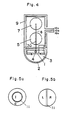
- piezoelectric vibrators 20a, 20b and 20c are mounted on a supporting member 14 which is rotatable arround a axle 4 supported through bearing 40. At one end of the axle 40, a pulley 60 is provided for transmitting rotation of a motor 5 to the supporting member 14 through another pulley 80 and a belt 6.
- rotary coils 30b and 31 b are embedded or mounted.
- a fixed coil 30a is embedded or mounted on inner side wall of a container 2 in opposite relation to the rotary coil 30b.
- a fixed coil 31 a is provided on a inner surface of a housing 5 5 in opposite relation to the rotary coil 30b.
- a third rotary coil 32b is provided which is opposite to a fixed coil 32a mounted on another surface of the housing 55.
- the fixed coiles 30a, 31a, 32a and the rotary coils 30b, 3 1 b, 32b are formed in spiral.
- Numeral 33 designates a magnetic core.
- a set of the fixed coil 30a, the rotary coil 30b and the magnetic core 33 forms a first flat type rotary transfarmer.
- a set of the fixed coil 3 1 a, the rotary coil 31 b and the magnetic coil 33, and a set of the fixed coil 32a, the rotary coil 32b and the magnetic coil 33 form second and third flat type rotary transformers.
- Each of the rotary transformers is electrically coupled to the rotating piezoelectric vibrators 20a, 20b and 20c with no contact relation.
- the magnetic cores 33 are made of magnetic material such as ferrite to improve efficiency of the rotary transformer and suppress electro-magnetic interference between each of the rotary transformers.
- the electro-magnetic interference between the ratary transformers is suppressed moreover by providing shielding plates 34 of magnetic material such as Permalloy between the rotary transformers.
- the supporting member 1 4 is rotated by the motor 5 through the pulley 80, the belt 6 and the pulley 60.
- the motor 5 is controlled to maintain constant rotation by rota- t i on controller 7.
- the piezoelectric vibrators 20a, 20b, and 20c are provided on outside surface of the supporting member 14 having equi-angular relation of 120°, and each piezoelectric vibrator scans 90° sector region respectively.
- Each of the piezoelectric vibrator has single or multi-layered acoustical matching layers for matching acoustical impedance between the object as ocasion demands.
- the inductance of the rotary transformers is also matched to the impedance of the piezoelectric vibrators 20a, 20b and 20c for raising efficiency of transmitting and receiving ultrasonic wave.
- a pulse signal is supplied to the fixed coil 30a to excite the piezoelectric vibrator 20a.
- the pulse signal is immediately induced to the rotaty coil 30b by electromagnetic induction and excite the piezoelectric vibrator 20a.
- the piezoelectric vibrator 20a generates a ultrasonic pulse beam.
- the ultrasonic pulse beam is emitted to the object through the container 2 which is fieled an ultrasonic wave propagating material 3 therein.
- a reflected beam obtained by the difference of acoustic impedance of the object is received by the piezoelectric vibrator 20a along a reverse passage.
- the received signal is transmitted to the fixed coil 30a through the rotary coil 30b by electromagnetic induction and supplied to a signal processor via a cable 110.
- the signal processor the received signal is processed and displayed as a brightness signal of one scanning line on a cathode ray tube.
- the piezoelectric vibrators 20b and 20c perform sector scanning operation of 90° sector.
- the supporting member 14 rotates in a rotating speed of 10 rps and the piezoelectric vibrators 20a, 20b and 20c are sequentially selected to the excited by switching the fixed coils 30a, 31 a and 32a with a semiconductor switching device 90, which is provided in the signal processor, in accordance with relative position of the piezoelectric vibrator 20a, 20b, and 20c to the object.
- a semiconductor switching device 90 which is provided in the signal processor
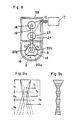
- an ultrasonic wave transmitting and receiving portion 1 comprises a piezoelectric vibrator, acoustic impedance matching layer and backing load member, which are integrated in piled layer.
- the piezoelectric vibrator or both of the piezoelectric vibrator and acoustic impedance matching layer are mechanically or electrically divided, as shown in Figs. 5a and 5b, into two regions by sound wave buffer member 11 such as a silicone rubber to decrease acoustic coupling between the two divided regions.
- the ultrasonic wave transmitting and receiving portion 1 of Fig. 4 employs the case shown in Fig. 5a. If no acoustic crosstalks occur, only the electrode of the piezoelectric vibrator may be divided as illustrated in Figs.
- the thus obtained ultrasonic wave transmitting and receiving portion 1 is located in the contrainer 2 which has an acoustic window made of resin having acoustic impedance matched with that of the human body such as poly- methylpentene.
- the container 2 is filled with the ultrasonic wave propagating material 3 such as deflated water or butanediol.
- the ultrasonic transmitting and receiving portion 1 is swung around the axis 4 by a belt or crank chain 6 driven with a motor 5.
- the motor 5 is linked to a controller 7 with a belt or gear 8 to adjust the rotation speed of the motor 5 in a predetermined value.
- the controller 7 is formed such as rotary encoder or a potentiameter.
- Numeral 9 designates a housing of the MSP.
- a lead wire 10a is connected to a common electrode of the piezoelectric vibrator, a lead wire 10b to an electrode of the piezoelectric vibrator I, a lead wire 10c to an electrode of the piezoelectric vibrator 0 respectively.
- the lead wires 10a, 10b and 10c are switched by a semiconductor switching device in a signal processing and displaying apparatus in accordance with the mode to be displayed. When 2D mode, M mode or pulse Doppler mode is displayed, the lead wires 10b and 10c are commonly connected.
- one of the lead wires 10b and 10c is used as a exclusive use for ultrasonic wave transmission and another a exclusive use for ultrasonic wave reception.
- the buffer region 11 does not influence to sound field because the buffer region 11 has very small area of 1/30 1/100 of that of the divided ultrasonic transmitting and receiving portion.
- Fig. 6 illustrates a second embodiment of the present invention.
- ultrasonic wave transmitting and receiving portion 1 container 2 having an acoustic window, ultrasonic wave propagating material 3, rotating axle 4, motor 5, belt or crank chain 6, controller 7 and housing 9 are same as those of Fig 4.
- Reference numeral 12 designates a signal transmitter, 13a connecting cable and 14 a supporting member respectively.
- the MSP of Fig. 6 is essentially same as that of Fig. 1 except the divided ultrasonic wave transmitting and receiving portion 1.
- the ultrasonic wave transmitting and receiving portion 1 is based on the structure as shown in Figs. 5a and 5b, but other various modification may be employed.
- Fig. 7a illustrates an example of the ultrasonic wave transmitting and receiving portion 1 of Fig. 6.
- the supporting member 14 has a quasi-triangular cross-section on each of the plane surface of which three ultrasonic wave transmitting and receiving portions 1 each having constructions shown in Fig. 5a are disposed.
- six signal transmission lines and one grounded line are connected to the signal processor and display apparatus through the signal transmitter 12.
- the signal transmitter 12 is formed with a rotary transformer same as previously described or a slip ring.
- Fig. 7b is another example of ultrasonic wave transmitting and receiving portion.
- the divided ultrasonic wave transmitting and receiving portion 1 is provided on one surface of the supporting member 1 4.
- non-divided ultrasonic wave transmitting and receiving portion 15 is provided.
- 2D mode, M mode or pulse Doppler mode is displayed, the ultrasonic wave transmitting and receiving portion 15 is used.
- CW Doppler mode is displayed, the ultrasonic wave transmitting and receiving portion 1 is used as same as previously described.
- piezoelectric vibrators 20a, 20b and 20c each having same aperture and different focal distances f1, f, and f, are provided on surfaces of a supporting member 14 in equi-angular relation.
- the supporting member 14 is rotated by a DC motor 23 through a gear or a belt 24.
- the supporting member 14 is located in a container 2 having acoustic window made of poly- methylpentene resin and ultrasonic wave propagating material 3 such as deflated water is filled in the container 2.
- the piezoelectric vibrators 20a, 20b, and 20c are electrically connected to a signal processing and displaying apparatus 17 through a singal transmitter 16 such as a rotary transformer or a slip ring.
- the signal transmitter 16, DC motor 23, and the encoder 18 are connected to the signal processing and displaying apparatus 17 through connecting wires 10.
- Numeral 55 designates a housing of the MSP.
- the signal processing and displaying apparatus 17 generates transmission signal, processes received signal such as amplifying, detecting, storing and scan converting, generates controlling signals for various subsystems, and displays the section image on a cathode ray tube. Generally these signal processing is not performed in the MSP.
- FIG. 9a an ultrasonic beam from the piezoelectric vibrator 20a having focal length of f, is shown by dotted line.
- an ultrasonic beams from the piezoelectric vibrator 20b having focal length of f" and the piezoelectric vibrator 20c having focal length of f are shown by different dotted lines.
- the piezoelectric vibrators 20a, 20b and 20c are selectively used in such a manner that most slender beam is selected. Namely, the piezoelectric vibrator 20a is used at Z, region, the piezoelectric vibrator 20b is used at Z, region, and the piezoelectric vibrator 20c is used at Z, region.
- Fig. 9b shows the ultrasonic beam thus obtained. As apparent from Fig. 9b, converged slender beam is obtained according to the embodiment of Fig. 8.
- the selection of desired ultrasonic beam is performed by the signal processing and displaying apparatus 17.
- the piezoelectric vibrator 20a is selected to extract and memorize informations in Z, region.
- the piezoelectric vibrator 20b is selected to extract and memorize informations in Z, region.
- the piezoelectric vibrator 20c is selected to extract and memorize informations in Z, region.
- the piezoelectric vibrators 22a, 22b, and 22c have different focal lengths f" f,, f, and different aperlures.
- resolution in Z, region is improved by using the piezoelectric vibrator 22a having small aperture.
- the ultrasonic beam obtained by the embodiment of Fig. 10a is illustrated in Fig. 10b.
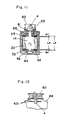
- a first coil 42 mounted on inner sidewall of a cell 32 and a second coil 4 3 mounted on a supporting means 14 forms two pair of rotary transformers each having coil gaps of d, and d, respectively.
- the supporting member 14 is supported to the cell 32 by bearings 81 and 82.
- the bearing 81 is stored in a bearing box 83.
- On outside of the bearing box 83 and corresponding surface of the cell 32 a screw-cuttings having very small pitch are formed. The screw-cuttings make possible to adjust the location of the supporting member 14, whereby the coil gaps d, and , are adjustable.
- another bearing 82 is suspended by a spring 84 which absorbs the change of thrust load occured by adjusting the supporting member 14 and prevents oscillation of axis of the supporting member 14.
- Numeral 85 designates an oil seal.
- the sum d 1 + d, of the coil gaps of the rotary transformer is decided by rotor length LR of the supporting member 14 and inner size Ls of the cell 32 and cannot be adjusted itself.
- the coil gap d is detected by measuring impedance of rotary transformer block. Therefore, electric characteristics of the rotary transformer block can be regulated by screwing the bearing box 83.
- a third coil 63 1 is further provided on a pulley 60 and chassis 83 in face to face manner as shown in Fig. 12. Impedance adjustment of the coil 63 1 is performed after adjusting two pair of coils of Fig. 11 described before.
Landscapes
- Physics & Mathematics (AREA)
- Engineering & Computer Science (AREA)
- Acoustics & Sound (AREA)
- Multimedia (AREA)
- Investigating Or Analyzing Materials By The Use Of Ultrasonic Waves (AREA)
- Ultra Sonic Daignosis Equipment (AREA)
- Transducers For Ultrasonic Waves (AREA)
Priority Applications (1)
| Application Number | Priority Date | Filing Date | Title |
|---|---|---|---|
| EP91111825A EP0455273B1 (de) | 1984-08-30 | 1985-08-30 | Ultraschallwandler für medizinische Diagnostik |
Applications Claiming Priority (4)
| Application Number | Priority Date | Filing Date | Title |
|---|---|---|---|
| JP181317/84 | 1984-08-30 | ||
| JP59181317A JPS6158648A (ja) | 1984-08-30 | 1984-08-30 | 機械走査式超音波探触子 |
| JP181316/84 | 1984-08-30 | ||
| JP59181316A JPS6158647A (ja) | 1984-08-30 | 1984-08-30 | 機械走査式超音波探触子 |
Related Child Applications (2)
| Application Number | Title | Priority Date | Filing Date |
|---|---|---|---|
| EP91111825.5 Division-Into | 1985-08-30 | ||
| EP91111825A Division EP0455273B1 (de) | 1984-08-30 | 1985-08-30 | Ultraschallwandler für medizinische Diagnostik |
Publications (2)
| Publication Number | Publication Date |
|---|---|
| EP0174167A2 true EP0174167A2 (de) | 1986-03-12 |
| EP0174167A3 EP0174167A3 (de) | 1988-12-14 |
Family
ID=26500551
Family Applications (2)
| Application Number | Title | Priority Date | Filing Date |
|---|---|---|---|
| EP91111825A Expired - Lifetime EP0455273B1 (de) | 1984-08-30 | 1985-08-30 | Ultraschallwandler für medizinische Diagnostik |
| EP85306166A Withdrawn EP0174167A3 (de) | 1984-08-30 | 1985-08-30 | Ultraschallwandler für medizinische diagnostische Untersuchung |
Family Applications Before (1)
| Application Number | Title | Priority Date | Filing Date |
|---|---|---|---|
| EP91111825A Expired - Lifetime EP0455273B1 (de) | 1984-08-30 | 1985-08-30 | Ultraschallwandler für medizinische Diagnostik |
Country Status (2)
| Country | Link |
|---|---|
| EP (2) | EP0455273B1 (de) |
| DE (1) | DE3588128T2 (de) |
Cited By (5)
| Publication number | Priority date | Publication date | Assignee | Title |
|---|---|---|---|---|
| EP0203717A1 (de) * | 1985-04-26 | 1986-12-03 | Matsushita Electric Industrial Co., Ltd. | Ultraschallsonde |
| EP0359546A3 (en) * | 1988-09-16 | 1990-05-02 | Hewlett-Packard Company | Ultrasound system with improved coupling fluid |
| WO1990013107A1 (en) * | 1989-04-25 | 1990-11-01 | Board Of Regents, The University Of Texas System | System for ultrasonic pan focal imaging and axial beam translation |
| US5052393A (en) * | 1988-09-16 | 1991-10-01 | Hewlett-Packard Company | Ultrasound system with improved coupling fluid |
| US7575552B2 (en) | 2004-06-10 | 2009-08-18 | Panasonic Corporation | Ultrasonic probe with acoustic medium |
Families Citing this family (1)
| Publication number | Priority date | Publication date | Assignee | Title |
|---|---|---|---|---|
| CN103675093B (zh) * | 2013-11-22 | 2016-04-27 | 国核电站运行服务技术有限公司 | 管材检测系统 |
Family Cites Families (4)
| Publication number | Priority date | Publication date | Assignee | Title |
|---|---|---|---|---|
| US4149419A (en) * | 1977-11-25 | 1979-04-17 | Smith Kline Instruments, Inc. | Ultrasonic transducer probe |
| DE3045623A1 (de) * | 1980-12-03 | 1982-06-24 | Siemens AG, 1000 Berlin und 8000 München | Ultraschall-applikator |
| US4424813A (en) * | 1981-08-14 | 1984-01-10 | Diasonics, Inc. | Multi-mode ultrasound scanner |
| AT384545B (de) * | 1981-12-01 | 1987-11-25 | Kretztechnik Gmbh | Ultraschall-untersuchungsgeraet |
-
1985
- 1985-08-30 EP EP91111825A patent/EP0455273B1/de not_active Expired - Lifetime
- 1985-08-30 DE DE3588128T patent/DE3588128T2/de not_active Expired - Lifetime
- 1985-08-30 EP EP85306166A patent/EP0174167A3/de not_active Withdrawn
Cited By (6)
| Publication number | Priority date | Publication date | Assignee | Title |
|---|---|---|---|---|
| EP0203717A1 (de) * | 1985-04-26 | 1986-12-03 | Matsushita Electric Industrial Co., Ltd. | Ultraschallsonde |
| US4677853A (en) * | 1985-04-26 | 1987-07-07 | Matsushita Electric Industrial Co., Ltd. | Ultrasonic probe |
| EP0359546A3 (en) * | 1988-09-16 | 1990-05-02 | Hewlett-Packard Company | Ultrasound system with improved coupling fluid |
| US5052393A (en) * | 1988-09-16 | 1991-10-01 | Hewlett-Packard Company | Ultrasound system with improved coupling fluid |
| WO1990013107A1 (en) * | 1989-04-25 | 1990-11-01 | Board Of Regents, The University Of Texas System | System for ultrasonic pan focal imaging and axial beam translation |
| US7575552B2 (en) | 2004-06-10 | 2009-08-18 | Panasonic Corporation | Ultrasonic probe with acoustic medium |
Also Published As
| Publication number | Publication date |
|---|---|
| EP0455273A2 (de) | 1991-11-06 |
| EP0455273B1 (de) | 1996-10-30 |
| DE3588128T2 (de) | 1997-04-30 |
| EP0174167A3 (de) | 1988-12-14 |
| DE3588128D1 (de) | 1996-12-05 |
| EP0455273A3 (en) | 1992-04-29 |
Similar Documents
| Publication | Publication Date | Title |
|---|---|---|
| US4452084A (en) | Inherent delay line ultrasonic transducer and systems | |
| EP0253268A1 (de) | Ultraschallsonde | |
| US4241611A (en) | Ultrasonic diagnostic transducer assembly and system | |
| US5400788A (en) | Apparatus that generates acoustic signals at discrete multiple frequencies and that couples acoustic signals into a cladded-core acoustic waveguide | |
| CN112353419B (zh) | 多阵元扫描式超声波探头及超声成像系统和超声成像方法 | |
| JPH074373B2 (ja) | 超音波内視鏡装置 | |
| EP0269314A2 (de) | Messkopf für Ultraschallabbildung | |
| US6160340A (en) | Multifrequency ultrasonic transducer for 1.5D imaging | |
| EP0455273B1 (de) | Ultraschallwandler für medizinische Diagnostik | |
| US4426886A (en) | Ultrasonic scanner | |
| US5211168A (en) | Moving electrode transducer for real time ultrasound imaging for use in medical applications | |
| EP0293803B1 (de) | Ultraschallgerät mit fächerförmiger Abtastung für die Fehlererkennung | |
| EP0306288B1 (de) | Ultraschall-Abbildungsgerät | |
| CN112472126B (zh) | 非整数维机械扫描式超声探头及成像系统和成像方法 | |
| GB1572617A (en) | Sound transducer head | |
| JPH0161060B2 (de) | ||
| JPH0160254B2 (de) | ||
| JP2000070268A (ja) | 超音波プローブ | |
| JPS5926303B2 (ja) | 超音波診断装置 | |
| JPH0248254B2 (de) | ||
| JPS61115546A (ja) | 超音波探触子 | |
| JPH03131242A (ja) | 超音波探触子 | |
| JP3236672B2 (ja) | 超音波診断装置 | |
| JPS6158648A (ja) | 機械走査式超音波探触子 | |
| JPH0464427B2 (de) |
Legal Events
| Date | Code | Title | Description |
|---|---|---|---|
| PUAI | Public reference made under article 153(3) epc to a published international application that has entered the european phase |
Free format text: ORIGINAL CODE: 0009012 |
|
| AK | Designated contracting states |
Kind code of ref document: A2 Designated state(s): DE FR GB |
|
| PUAL | Search report despatched |
Free format text: ORIGINAL CODE: 0009013 |
|
| AK | Designated contracting states |
Kind code of ref document: A3 Designated state(s): DE FR GB |
|
| 17P | Request for examination filed |
Effective date: 19890614 |
|
| 17Q | First examination report despatched |
Effective date: 19901031 |
|
| STAA | Information on the status of an ep patent application or granted ep patent |
Free format text: STATUS: THE APPLICATION IS DEEMED TO BE WITHDRAWN |
|
| 18D | Application deemed to be withdrawn |
Effective date: 19911031 |
|
| RIN1 | Information on inventor provided before grant (corrected) |
Inventor name: KAWACUHI, MASAMI Inventor name: MURAMATSU, FUMIO |