EP0269314A2 - Messkopf für Ultraschallabbildung - Google Patents
Messkopf für Ultraschallabbildung Download PDFInfo
- Publication number
- EP0269314A2 EP0269314A2 EP87309958A EP87309958A EP0269314A2 EP 0269314 A2 EP0269314 A2 EP 0269314A2 EP 87309958 A EP87309958 A EP 87309958A EP 87309958 A EP87309958 A EP 87309958A EP 0269314 A2 EP0269314 A2 EP 0269314A2
- Authority
- EP
- European Patent Office
- Prior art keywords
- transducer
- segments
- assembly
- ultrasonic
- housing
- Prior art date
- Legal status (The legal status is an assumption and is not a legal conclusion. Google has not performed a legal analysis and makes no representation as to the accuracy of the status listed.)
- Withdrawn
Links
Images

Classifications
-
- G—PHYSICS
- G10—MUSICAL INSTRUMENTS; ACOUSTICS
- G10K—SOUND-PRODUCING DEVICES; METHODS OR DEVICES FOR PROTECTING AGAINST, OR FOR DAMPING, NOISE OR OTHER ACOUSTIC WAVES IN GENERAL; ACOUSTICS NOT OTHERWISE PROVIDED FOR
- G10K11/00—Methods or devices for transmitting, conducting or directing sound in general; Methods or devices for protecting against, or for damping, noise or other acoustic waves in general
- G10K11/18—Methods or devices for transmitting, conducting or directing sound
- G10K11/26—Sound-focusing or directing, e.g. scanning
- G10K11/35—Sound-focusing or directing, e.g. scanning using mechanical steering of transducers or their beams
- G10K11/352—Sound-focusing or directing, e.g. scanning using mechanical steering of transducers or their beams by moving the transducer
- G10K11/355—Arcuate movement
Definitions
- This invention relates to ultrasonic imaging probe assemblies.
- the invention relates to hand-held ultrasonic imaging probe assemblies suitable for diagnostic ultrasound imaging.
- Diagnostic ultrasound imaging systems utilize piezoelectric transducer elements that convert electronic energy into mechanical movement to direct ultrasonic waves into a patient. Such systems utilize an ultrasonic transducer, imaging electronics, and a display.
- the imaging electronics actuate the transducer for propagation of ultrasonic energy into a patient's body. Within the body, the ultrasonic energy echoes or bounces off structures within the patient and returns to the transducer.
- the imaging electronics then process electrical output signals from the transducer to present a visual indication of the internal structure of the patient.
- US-A-4,537,074 discloses one such transducer array. As disclosed in US-A-4,537,074, it is known to pivotally mount such an annular array of transducer segments to cause ultrasonic energy emitted by the transducer to scan across a section of the patient. Use of a plurality of individually energized annular segments allows a transducer focal spot to be controlled. This is accomplished by applying appropriate electronic delays to the energization signals driving the transducer and/or sensed signals coming from the transducer. Use of ultrasonic transducers employing multiple segment arrays provide high resolution and improved depth of field in the displayed image.
- a later hand-held annular design transducer utilized a smaller transducer facing an oscillating mirror.
- the performance of this design was somewhat limited due to the small size of the transducer array.
- an ultrasonic imaging probe assembly comprising: a generally tubular housing; an ultrasonic transducer movably disposed within said housing and having a plurality of discrete segments, each said segment being capable of being individually energised; a drive means disposed within said housing and coupled to said ultrasonic transducer for imparting motion to said ultrasonic transducer; a power means for imparting motion to said drive means; and electrically conductive means coupled to said transducer for connecting said transducer to external circuitry, characterised in that said electrically conductive means comprises a bundle of individually insulated conductors including: a center signal carrying ocnductor coupled to one of said segments for carrying signals to and from said external circuitry; a plurality of reference conductors surrounding said center conductor and maintained at a reference potential; and a plurality of additional signal carrying conductors spaced from said center signal carrying conductor by said plurality of reference conductors, each conductor of said plurality of signal carrying conductors being
- an ultrasonic imaging probe assembly comprising: a generally tubular housing; an ultrasonic transducer movably disposed within said housing and having a plurality of discrete segments, each said segment being capable of being individually energised; a drive means disposed within said housing and coupled to said ultrasonic transducer for imparting motion to said ultrasonic transducer; a power means for imparting motion to said drive means; and electrically conductive means coupled to said transducer for connecting said transducer to external circuitry, characterised in that said assembly further comprises an ultrasonic window in said housing; said ultrasonic transducer faces said window and is orientated to direct energy through said window; said plurality of discrete segments comprises a center disk segment, an inner grouping of annular segments, and an outer grouping of truncated annular segments, said discrete segments in combination forming an elongated transducer surface; said drive means imparts to said ultrasonic transducer a rocking motion about a pivot
- an ultrasonic imaging probe assembly comprising: a generally tubular housing; an ultrasonic transducer movably disposed within said housing and having a plurality of discrete segments, each said segment being capable of being individually energised; a drive means disposed within said housing and coupled to said ultrasonic transducer for imparting motion to said ultrasonic transducer; a power means for imparting motion to said drive means; and electrically conductive means coupled to said transducer for connecting said transducer to external circuitry, characterised in that said drive means imparts to said transducer motion about a pivot axis; and said assembly further comprises an ultrasonic window comprising a cup that encloses one end of the tubular housing, said cup defining an annular shaped housing and a blunt generally planar probe end, said probe end being bounded by first and second curved side portions, said first curved side portion defining first and second arcuate side regions and said second curved side portions defining first and second pinched
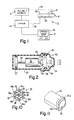
- FIG. 1 illustrates an ultrasonic imaging system S incorporating the present invention.
- the system includes a hand-held ultrasonic probe 10, circuitry 12 for both pulsing and receiving signals from the probe, imaging circuitry 14, and display apparatus 16.
- the system S propagates ultrasonic energy into a subject (not shown).
- the system responds to ultrasonic echoes thereby generated to produce a sector image 26 corresponding to the pattern of received ultrasonic echoes and indicating internal structure and/or condition of the subject's body.
- the probe 10 includes an ultrasonic transducer generally indicated at 18, a motor 20 for mechanically oscillating the transducer, and an encoder 22 for providing a substantially instantaneous indication of the azimuthal orientation of the transducer.
- the pulse/receiving circuitry 12 directs electrical pulsing signals over a multi-conductor cable 28 to the transducer 18, causing the transducer to propagate ultrasonic energy into the subject body.
- the pulse/receiving circuitry 12 directs electrical pulsing signals over a multi-conductor cable 28 to the transducer 18, causing the transducer to propagate ultrasonic energy into the subject body.
- ultrasonic echoes occur at tissue interfaces within the subject's body, some of the echoes are propagated back to the transducer.
- the transducer produces electrical output signals which are detected by the circuitry 12.
- the pulse/receive circuitry 12 transmits the echo indicating transducer output signals to the imaging circuitry 14.
- the imaging circuitry 14 also receives a signal over a conductor 24 coupled to the encoder 22 indicating the instantaneous orientation of the transducer 18.
- the imaging circuitry 14 processes the detected echo indicating signals and the orientation indicating signal from the encoder to produce, on the display apparatus 16, which comprises a CRT display set, a sector image 26 describing internal subject body structure.
- the system S corresponds generally to the imaging system disclosed in DE-A-3618082.
- the probe 10 includes a housing comprising a first cylindrical portion 30 made of a generally rigid material, such as durable plastic, closed at the left hand end as viewed in Figure 2.
- the probe 10 also includes an ultrasound transmitting window 32 that fits within a flared opening of the cylindrical portion 30.
- the window 32 is made of a polyethylene which facilitates the passage of ultrasonic energy between the transducer and the exterior of the housing. In use, the window 32 is held against the subject's body in order to couple ultrasonic energy emmanating from the probe to the body.
- the interior of the probe 10 in the vicinity of the transducer 18, indicated at reference character 34 defines a cavity filled with a liquid acoustic couplant material.
- the motor 20 comprises a brushless DC motor having very low inertia.
- the motor 20 is operated by known servo power circuitry (not shown) in a limited rotation mode. Angular displacement of the motor is approximately + 45° with respect to a predetermined center position.
- the encoder 22 is an optical encoder coupled rigidly to the motor 20 by a shaft 36. It is a three channel encoder preferably having two data channels of 512 cycles per channel, and an index channel.
- the transducer 18 is pivotally mounted for rotational movement about an axis 38. More specifically, the transducer 18 is mounted to a transducer assembly 40 which is journalled in bearings 42, 44 for rotation about the axis 38, which is substantially perpendicular to the longitudinal axis of the tubular housing portion 30.
- the assembly 40 is driven by a motor drive shaft 46 by way of a pair of beveled gears 48, 50.
- the bevel gear 48 is mounted axially on the shaft 46, the bevel gear 50 being coupled to the transducer assembly 40.
- a seal (not shown) but disclosed in DE-A-3618082. prevents fluid from contacting the motor bearings that support the shaft 46.
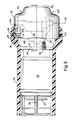
- FIG 3 illustrates in detail a probe assembly embodying the present invention and corresponding to that shown in Figure 2.
- an annular shaped housing end 32a of the window 32 defines an enclosure that fits within an annular flared recess in the housing portion 30 and abuts an annular flange or shoulder 51 defined by the housing 30.
- the housing 30 also defines an annular slot 52 for receipt of an O-ring 54 that prevents ultrasound coupling material that is applied to the patient from reaching the housing interior.
- a stationary transducer mounting member 60 Radially inward from an annular portion of the window 32 is a stationary transducer mounting member 60 ( Figure 4) that pivotally supports the transducer assembly 40.
- the transducer mounting member 60 defines a through passage 62 for accommodating the bevel gear 48 and motor drive shaft 46.
- the mounting member 60 is rigidly attached to a motor housing 31 in the housing 30 by threaded connectors 64 engaging a threaded opening in an endface 60a of the mounting member 60.
- a region 34 between the window portion 32 and the transducer assembly 40 is filled with a liquid couplant.
- an annular groove 65 in the mounting member 60 supports a second O-ring 66 that seals couplant within the region 34.
- a second annular groove or recess 67 in the mounting member 60 is engaged by a flange 32b of the window 32 to couple the window 32 to the housing portion 30. Inward pressure on the annular portion 32a of the window 32 by the compressed O-ring 54 keeps the flange 32b seated in the groove 67.
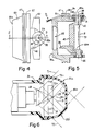
- FIGS 7-9 illustrate a transducer 18 constructed in accordance with the invention.
- the illustrated transducer is constructed from multiple transducer segments or elements 70a-70g.
- a face plate of the transducer (not shown) is plated onto the transducer elements 70a-70g and is maintained at electric ground.
- the face plate is constructed from an electrically conductive material which is transparent to ultrasonic waves emitted by the transducer 18.
- a first center transducer segment 70a is disk shaped as seen from the plane of the housing window 32.
- the next three transducer segments 70b-70d comprise annular piezo-electric elements symmetrically oriented about the center element 70a.
- Three additional segments 70e-70g comprise portions of annular members that are truncated along edge portions 72a, 72b of the transducer 18.
- the edges 72a, 72b approximate chords of a circle having a radius equal to the outer radius of the outermost transducer segment 70g.
- Each of the segments 70a-70g is spaced apart from adjacent elements by an acoustically absorptive material known in the prior art.
- a transducer holder 75 borders the segments 70a-70g and is also constructed from an acoustically absorptive material.
- the transducer 18 is slightly concave and in particular, a piezo-electric transducer surface 73 facing the window 32 has a focal length of approximately 90 millimeters.
- Seven electrical contact pads 74 coupled to the segments 70a-70g are illustrated in the rear elevation view of the transducer 18 of Figure 9. These contact pads are insulated from a transducer face plate maintained at a ground potential.
- the physical dimensions of the transducer 18 are noted in Figure 7.
- the transducer 18 is fixedly attached to the transducer mounting assembly 40 within a recess 40a ( Figure 5) defined by that assembly.
- Pivoting motion of the transducer 18 about the pivot axis 38 defined by the two bearings 42, 44 is illustrated in Figure 6.
- the transducer 18 is shown pivoting ⁇ 45° to generate acoustic waveforms 71, 72 traveling through the window 32 at 90° angles. It should be appreciated that the transducer segments 70a-70g are pulsed as the pivoting occurs so that acoustic signals sweep out a complete sector scan of a patient.
- the window 32 is flattened on one end to define a blunt, generally planar probe end 32p.
- the probe end 32p is bounded by first and second side portions.
- First side portions are defined by first and second arcuate side regions 32c and 32d.
- a curved edge 72c of the transducer 18 defined by the outermost truncated annular segment 70g rotates in close proximity to the first arcuate side region 32c.
- the second arcuate side region 32d defines a region for rotation of a second curved edge 72d of the transducer.
- the planar probe end 32p is only wide enough to accommodate movement of the truncated transducer 70.
- the second side portions of the window 32 are therefore pinched to define first and second pinched-in side regions 32e, 32f.
- each of the pinched-in side regions form a convex, then concave, then convex surface between the planar probe end 32p and the annular housing end 32a.
- pivot axis 38 An additional factor in reducing the size of the window 32 is the choice of pivot axis 38.
- the axis 38 passes through the transducer ground plane that fronts the array of segments.
- the transducer 18 rotates through a relatively small volume of the probe assembly since its side to side motion is minimal.
- An alternate axis 38a ( Figure 6) could be chosen between the window 32 and the transducer 18. This would result in greater transducer movement but not greater width of the acoustic transmitting portions of the window 32.
- a pivoting axis coincident with or ahead of the transducer 18 therefore also contributes (see Figure 6) to a reduced size of the window 32.
- the transducer mounting member 60 defines a through passage 80 for routing a cable 90 from inside the housing 30 through the mounting member 60 to a cable take-up mechanism 82.
- the cable take-up mechanism 82 is coupled to the transducer assembly 40 for rotation as the drive motor 20 oscillates the assembly 40 back and forth.
- the cable 90 ( Figure 10) is reeved about a groove 82a in the cable take-up 82.
- the cable take-up 82 defines an opening extending radially inward to a throughpassage 94 aligned with the pivot axis 38 of the transducer assembly 40.
- the passageway 94 extends along the pivot axis to the vicinity of the connecting pads 74 of Figure 9.
- individual signal carrying conductors ( Figure 10) are electrically connected to the pads 74 coupled to individual segments 70a-70g of the transducer 18.
- the take-up mechanism 82 accommodates a slack in the cable 90 so that the oscillating motion of the transducer 18 does not break the cable 90 as it is repeatedly flexed back and forth.
- the cable 90 mates with seven conventional signal carrying coaxial cables 91 which could not withstand the flexing and would take up much more space than the cable 90.
- the physical arrangement of individual signal carrying wires or conductors within in the cable 90 provides a compact, sturdy routing of transducer energization signals to the transducer.
- seven signal carrying wires are needed.
- the cable 90 is seen to include 19 individual conductors, each coated with an insulation material.
- Seven signal carrying conductors 96a-96g are separated from each other by reference conductors 98 maintained at ground potential.
- the 19 conductors are constructed of commonly known "magnet" wire used in motor and relay coil windings. Each wire has a small diameter, typically .004 inches, so that the entire hexagonal bundle of 19 conductors shown in Figure 10 has a width of only .02 inches.
- the arrangement of signal carrying conductors spaced from each other by the ground conductors 90 reduces cross-talk of induced signals created by the alternating current signals transmitted along the signal carrying wires.
- the entire bundle of 19 conductors is wrapped by a sheath (not shown) to facilitate routing of the cable 90 from within the housing 20 to the vicinity of the transducer 18.
Landscapes
- Physics & Mathematics (AREA)
- Engineering & Computer Science (AREA)
- Acoustics & Sound (AREA)
- Multimedia (AREA)
- Ultra Sonic Daignosis Equipment (AREA)
- Transforming Light Signals Into Electric Signals (AREA)
- Transducers For Ultrasonic Waves (AREA)
- Measurement Of Velocity Or Position Using Acoustic Or Ultrasonic Waves (AREA)
- Investigating Or Analyzing Materials By The Use Of Ultrasonic Waves (AREA)
Applications Claiming Priority (2)
| Application Number | Priority Date | Filing Date | Title |
|---|---|---|---|
| US935582 | 1986-11-26 | ||
| US06/935,582 US4762002A (en) | 1986-11-26 | 1986-11-26 | Probe array for ultrasonic imaging |
Publications (2)
| Publication Number | Publication Date |
|---|---|
| EP0269314A2 true EP0269314A2 (de) | 1988-06-01 |
| EP0269314A3 EP0269314A3 (de) | 1989-04-26 |
Family
ID=25467382
Family Applications (1)
| Application Number | Title | Priority Date | Filing Date |
|---|---|---|---|
| EP87309958A Withdrawn EP0269314A3 (de) | 1986-11-26 | 1987-11-11 | Messkopf für Ultraschallabbildung |
Country Status (3)
| Country | Link |
|---|---|
| US (1) | US4762002A (de) |
| EP (1) | EP0269314A3 (de) |
| JP (1) | JPS63142283A (de) |
Cited By (2)
| Publication number | Priority date | Publication date | Assignee | Title |
|---|---|---|---|---|
| FR2651990A1 (fr) * | 1989-09-15 | 1991-03-22 | Philips Electronique Lab | Sonde pour echographie en trois dimensions. |
| CN110356733A (zh) * | 2019-08-27 | 2019-10-22 | 嘉兴中科声学科技有限公司 | 防爆信标及液体储存罐 |
Families Citing this family (18)
| Publication number | Priority date | Publication date | Assignee | Title |
|---|---|---|---|---|
| USD304760S (en) | 1987-01-22 | 1989-11-21 | Diasonics, Inc. | Combined prostate and vaginal ultrasound probe |
| DE8717504U1 (de) * | 1987-10-19 | 1989-01-05 | Siemens AG, 1000 Berlin und 8000 München | Stoßwellenquelle mit zentralem Ultraschall-Ortungssystem |
| JPH01153145A (ja) * | 1987-12-11 | 1989-06-15 | Toshiba Corp | アニュラアレイ超音波探触子 |
| JPH03272752A (ja) * | 1990-03-20 | 1991-12-04 | Fujitsu Ltd | 超音波探触子 |
| US5243989A (en) * | 1990-05-11 | 1993-09-14 | Olympus Optical Co., Ltd. | Ultrasonic imaging device with noise preventing structure |
| US5117832A (en) * | 1990-09-21 | 1992-06-02 | Diasonics, Inc. | Curved rectangular/elliptical transducer |
| GB9109881D0 (en) * | 1991-05-08 | 1991-07-03 | Advanced Tech Lab | Transesophageal echocardiography scanner with rotating image plane |
| JPH06285106A (ja) * | 1993-03-30 | 1994-10-11 | Shimadzu Corp | 超音波治療装置 |
| US5398691A (en) * | 1993-09-03 | 1995-03-21 | University Of Washington | Method and apparatus for three-dimensional translumenal ultrasonic imaging |
| US5562096A (en) * | 1994-06-28 | 1996-10-08 | Acuson Corporation | Ultrasonic transducer probe with axisymmetric lens |
| US6287261B1 (en) * | 1999-07-21 | 2001-09-11 | Scimed Life Systems, Inc. | Focused ultrasound transducers and systems |
| US6780153B2 (en) * | 2001-06-25 | 2004-08-24 | Angelsen Bjoern A. J. | Mechanism and system for 3-dimensional scanning of an ultrasound beam |
| US20040254466A1 (en) * | 2003-06-16 | 2004-12-16 | James Boner | Apparatus and method for real time three-dimensional ultrasound imaging |
| FR2866801B1 (fr) * | 2004-02-27 | 2006-12-01 | Quantel Medical | Sonde echographique a balayage sectoriel utilisant un transducteur apte a venir au contact de la structure a examiner |
| US20090247879A1 (en) * | 2004-03-09 | 2009-10-01 | Angelsen Bjorn A J | Extended ultrasound imaging probe for insertion into the body |
| US20050203416A1 (en) * | 2004-03-10 | 2005-09-15 | Angelsen Bjorn A. | Extended, ultrasound real time 2D imaging probe for insertion into the body |
| US10603008B2 (en) * | 2009-02-19 | 2020-03-31 | Tessonics Corporation | Ultrasonic device for assessment of internal tooth structure |
| CN114098821B (zh) * | 2021-12-24 | 2025-04-25 | 深圳市影越医疗科技有限公司 | 一种超声探头 |
Family Cites Families (16)
| Publication number | Priority date | Publication date | Assignee | Title |
|---|---|---|---|---|
| US3906431A (en) * | 1965-04-09 | 1975-09-16 | Us Navy | Search and track sonar system |
| US4391281A (en) * | 1977-01-06 | 1983-07-05 | Sri International | Ultrasonic transducer system and method |
| FI62950C (fi) * | 1978-03-27 | 1983-04-11 | New York Inst Techn | Undersoekningsmodul till en ultraljudsavbildningsanordning |
| US4248090A (en) * | 1978-03-27 | 1981-02-03 | New York Institute Of Technology | Apparatus for ultrasonically imaging a body |
| US4421118A (en) * | 1981-08-12 | 1983-12-20 | Smithkline Instruments, Inc. | Ultrasonic transducer |
| US4543960A (en) * | 1983-04-11 | 1985-10-01 | Advanced Technology Laboratories, Inc. | Transesophageal echo cardiography scanhead |
| US4615330A (en) * | 1983-09-05 | 1986-10-07 | Olympus Optical Co., Ltd. | Noise suppressor for electronic endoscope |
| US4537074A (en) * | 1983-09-12 | 1985-08-27 | Technicare Corporation | Annular array ultrasonic transducers |
| JPS6080443A (ja) * | 1983-10-07 | 1985-05-08 | 株式会社エスジー | 超音波走査装置 |
| US4579123A (en) * | 1983-12-16 | 1986-04-01 | Hewlett-Packard Company | Stand-off device |
| CA1252553A (en) * | 1984-09-25 | 1989-04-11 | John G. Abbott | Ultrasonic compound scan with a rotating transducer |
| BR8505666A (pt) * | 1984-11-13 | 1986-08-12 | Du Pont | Cabo de transmissao tendo camadas concentricas de condutores |
| JPS61135637A (ja) * | 1984-12-07 | 1986-06-23 | 株式会社東芝 | 超音波プロ−ブ |
| JPS61144565A (ja) * | 1984-12-18 | 1986-07-02 | Toshiba Corp | 高分子圧電型超音波探触子 |
| DE3669008D1 (de) * | 1985-04-04 | 1990-03-15 | Philips Nv | Zusammengesetzter draht fuer hf-anwendungen, mit solch einem draht gewickelte spule und solch eine spule enthaltende ablenkeinheit. |
| US4773426A (en) * | 1985-06-03 | 1988-09-27 | Picker International, Inc. | Ultrasonic mechanical sector scanning transducer probe assembly |
-
1986
- 1986-11-26 US US06/935,582 patent/US4762002A/en not_active Expired - Fee Related
-
1987
- 1987-11-11 EP EP87309958A patent/EP0269314A3/de not_active Withdrawn
- 1987-11-26 JP JP62298845A patent/JPS63142283A/ja active Pending
Cited By (2)
| Publication number | Priority date | Publication date | Assignee | Title |
|---|---|---|---|---|
| FR2651990A1 (fr) * | 1989-09-15 | 1991-03-22 | Philips Electronique Lab | Sonde pour echographie en trois dimensions. |
| CN110356733A (zh) * | 2019-08-27 | 2019-10-22 | 嘉兴中科声学科技有限公司 | 防爆信标及液体储存罐 |
Also Published As
| Publication number | Publication date |
|---|---|
| JPS63142283A (ja) | 1988-06-14 |
| US4762002A (en) | 1988-08-09 |
| EP0269314A3 (de) | 1989-04-26 |
Similar Documents
| Publication | Publication Date | Title |
|---|---|---|
| EP0269314A2 (de) | Messkopf für Ultraschallabbildung | |
| EP0375132B1 (de) | Mechanisch steuerbare Miniatur-Ultraschallsonde | |
| US4149419A (en) | Ultrasonic transducer probe | |
| US4375818A (en) | Ultrasonic diagnosis system assembled into endoscope | |
| US5226422A (en) | Transesophageal echocardiography scanner with rotating image plane | |
| US4977898A (en) | Miniaturized encapsulated ultrasonic transducer | |
| US5070879A (en) | Ultrasound imaging method and apparatus | |
| US4834102A (en) | Endoscope for transesophageal echocardiography | |
| US5195519A (en) | Miniaturized mechanically-steerable ultrasonic probe | |
| EP0129878B1 (de) | Ultraschallkopf mit einem zweifach bewegbaren Wandler | |
| CA1129062A (en) | Ultrasonic sector scanner | |
| US5400788A (en) | Apparatus that generates acoustic signals at discrete multiple frequencies and that couples acoustic signals into a cladded-core acoustic waveguide | |
| US4205686A (en) | Ultrasonic transducer and examination method | |
| EP0090567B1 (de) | Ultraschallsonde zur Sektorabtastung | |
| US4374525A (en) | Ultrasonic diagnostic apparatus for endoscope | |
| EP0184337B1 (de) | Sonden mit lenkbarem Dopplereffektwandler | |
| US4426886A (en) | Ultrasonic scanner | |
| US4773426A (en) | Ultrasonic mechanical sector scanning transducer probe assembly | |
| US4869257A (en) | Ultrasonic mechanical sector scanning transducer probe assembly | |
| US6712765B2 (en) | Ultrasonic scanning method and apparatus | |
| EP0429799B1 (de) | Ultraschall-Bilddarstellungsverfahren und Gerät | |
| GB2099997A (en) | Apparatus for ultrasonic imaging | |
| EP1698281B1 (de) | Ultraschallsonde | |
| GB2082769A (en) | Improvements in Ultrasonic Diagnosis Systems | |
| JPH0965477A (ja) | 超音波トランスデューサ |
Legal Events
| Date | Code | Title | Description |
|---|---|---|---|
| PUAI | Public reference made under article 153(3) epc to a published international application that has entered the european phase |
Free format text: ORIGINAL CODE: 0009012 |
|
| AK | Designated contracting states |
Kind code of ref document: A2 Designated state(s): DE FR GB NL |
|
| PUAL | Search report despatched |
Free format text: ORIGINAL CODE: 0009013 |
|
| AK | Designated contracting states |
Kind code of ref document: A3 Designated state(s): DE FR GB NL |
|
| 17P | Request for examination filed |
Effective date: 19891012 |
|
| 17Q | First examination report despatched |
Effective date: 19910528 |
|
| STAA | Information on the status of an ep patent application or granted ep patent |
Free format text: STATUS: THE APPLICATION IS DEEMED TO BE WITHDRAWN |
|
| 18D | Application deemed to be withdrawn |
Effective date: 19911008 |
|
| RIN1 | Information on inventor provided before grant (corrected) |
Inventor name: ADAMS, DARWIN P. |