EP0174221A1 - Erdnussablagerungsgerät und Ablagerungsverfahren zur Konfektherstellung - Google Patents
Erdnussablagerungsgerät und Ablagerungsverfahren zur Konfektherstellung Download PDFInfo
- Publication number
- EP0174221A1 EP0174221A1 EP85401445A EP85401445A EP0174221A1 EP 0174221 A1 EP0174221 A1 EP 0174221A1 EP 85401445 A EP85401445 A EP 85401445A EP 85401445 A EP85401445 A EP 85401445A EP 0174221 A1 EP0174221 A1 EP 0174221A1
- Authority
- EP
- European Patent Office
- Prior art keywords
- articles
- moving member
- air
- upstanding
- side wall
- Prior art date
- Legal status (The legal status is an assumption and is not a legal conclusion. Google has not performed a legal analysis and makes no representation as to the accuracy of the status listed.)
- Granted
Links
Images


Classifications
-
- A—HUMAN NECESSITIES
- A21—BAKING; EDIBLE DOUGHS
- A21C—MACHINES OR EQUIPMENT FOR MAKING OR PROCESSING DOUGHS; HANDLING BAKED ARTICLES MADE FROM DOUGH
- A21C9/00—Other apparatus for handling dough or dough pieces
- A21C9/04—Apparatus for spreading granular material on, or sweeping or coating the surfaces of, pieces or sheets of dough
-
- A—HUMAN NECESSITIES
- A23—FOODS OR FOODSTUFFS; TREATMENT THEREOF, NOT COVERED BY OTHER CLASSES
- A23G—COCOA; COCOA PRODUCTS, e.g. CHOCOLATE; SUBSTITUTES FOR COCOA OR COCOA PRODUCTS; CONFECTIONERY; CHEWING GUM; ICE-CREAM; PREPARATION THEREOF
- A23G3/00—Sweetmeats; Confectionery; Marzipan; Coated or filled products
- A23G3/02—Apparatus specially adapted for manufacture or treatment of sweetmeats or confectionery; Accessories therefor
- A23G3/20—Apparatus for coating or filling sweetmeats or confectionery
- A23G3/2007—Manufacture of filled articles, composite articles, multi-layered articles
- A23G3/2023—Manufacture of filled articles, composite articles, multi-layered articles the material being shaped at least partially in a mould, in the hollows of a surface, a drum, an endless band or by drop-by-drop casting or dispensing of the materials on a surface or an article being completed
- A23G3/203—Apparatus for laying down the liquid, pasty or solid materials in moulds or drop-by-drop, on a surface or an article being completed, optionally with the associated heating, cooling, proportioning, cutting cast-tail, antidripping device
-
- A—HUMAN NECESSITIES
- A23—FOODS OR FOODSTUFFS; TREATMENT THEREOF, NOT COVERED BY OTHER CLASSES
- A23G—COCOA; COCOA PRODUCTS, e.g. CHOCOLATE; SUBSTITUTES FOR COCOA OR COCOA PRODUCTS; CONFECTIONERY; CHEWING GUM; ICE-CREAM; PREPARATION THEREOF
- A23G3/00—Sweetmeats; Confectionery; Marzipan; Coated or filled products
- A23G3/02—Apparatus specially adapted for manufacture or treatment of sweetmeats or confectionery; Accessories therefor
- A23G3/20—Apparatus for coating or filling sweetmeats or confectionery
- A23G3/2076—Apparatus for coating with powders or granules, e.g. sprinkling
-
- A—HUMAN NECESSITIES
- A23—FOODS OR FOODSTUFFS; TREATMENT THEREOF, NOT COVERED BY OTHER CLASSES
- A23P—SHAPING OR WORKING OF FOODSTUFFS, NOT FULLY COVERED BY A SINGLE OTHER SUBCLASS
- A23P20/00—Coating of foodstuffs; Coatings therefor; Making laminated, multi-layered, stuffed or hollow foodstuffs
- A23P20/10—Coating with edible coatings, e.g. with oils or fats
- A23P20/12—Apparatus or processes for applying powders or particles to foodstuffs, e.g. for breading; Such apparatus combined with means for pre-moistening or battering
Definitions
- the rope may be an. extrudate rope, or it may be formed by rolling or other forming operations.
- the extrudate rope 100 can be formed by extrusion through an opening while the rope is hot.
- the extrudate shortly after being extruded, bei.ng relatively thick and hot, must be cooled so that it does not either fall apart or flatten during further processing. While following a cooling path the extrudate rope 100 can be stretched.
- the extrudate rope at this early stage is slightly non-uniform, and is preferrably cooled along a relatively long path during which it is preferrably stretched at a pair of rollers so as to be suspended and so as to be formed by stretching into a relatively uniform size. While suspended the extrudate rope, which is preferrably composed of fudge at this point, can be surrounded by caramel at a nozzle inlet and can thereby be is coated by the caramel which adheres to the fudge.
- the extrudate rope passes through a trough containing peanuts so that peanuts surround the extrudate rope 100.
- the caramel being sticky, causes some of the peanuts to adhere to the extrudate rope 100.
- the extrudate rope at this point, is relatively cool and resists stretching, so that further operations can be made upon the extrudate rope 100.
- the extrudate rope is then cut by a guillotine cutter into bars having a relatively uniform length.
- the bars are then inspected to see that a relatively uniform coating of peanuts is maintained upon each bar. Due to the uneven distribution of peanuts upon some of the bars, those bars must be rejected. During this process, approximately 30% of the bars must be rejected for uneven peanut distribution. This is a significant problem which is addressed by the present invention.
- extrudate rope Although a single extrudate rope has been discussed, ordinarily multiple rows of extrudate ropes are processed simultaneously. In one apparatus, for example, 16 rows across are used.
- the extrudate rope of fudge which is initially formed, is formed into a relatively square sided bar. After coating with caramel and peanuts, the bar assumes a somewhat more rounded shape.
- candy bars Following deposition of the peanuts, a chocolate coating is dripped on the product, After cooling, this chocolate-coated bar forms the end product.
- This end product is referred to hereinafter as candy bars.
- a nut dispenser assembly is shown in figures 1, 3, and 4.
- a dispenser housing 48 has an impeller 52 with impeller blades 53 mounted on a drum 54 thereof. The impeller is keyed to one end of an impeller shaft 59.
- the final product has a nougat center that is coated with caramel and a layer of salted nuts which are at least partially embedded in the caramel.
- the impeller 52 through its rotation deposits a layer of salted peanuts on the belt 43.
- the sidewalls of the dispenser serves to retain nuts on the belt.
- a vibrator 13 spreads the nuts in an even layer as shown in figure 17.
- the belt travels under a caramel dispenser nozzle 202. If the caramel is too hot, it will melt the nougat; if too cold, it will not properly adhere to the peanuts.
- the fruit and nut feeding mechanism of Fogt introduces pieces of edible solids such as fruits or nuts into a flowing stream of plastic comestible material such as semi-frozen ice cream, water ice, or sherbet. Fogt attempts to avoid crushing of the solid edible pieces such as fruits or nuts during dispensing thereof.
- a plurality of pockets ar.e movable into position to receive the solid articles by gravity directly from an outlet of a hopper.
- a mechanism is used to stir a mass of solid pieces in a hopper to maintain a flow of pieces.
- Each pocket is periodically moved into and out of communication with the confined path of travel of the plastic stream and the contents of each pocket are forcably injected into the flowing stream.
- the mouth of the pockets are sealed as they pass from charging to discharging position, and from discharging to charging position.
- Lifting fingers are provided near the hopper outlet. These are operated by operating rods which lie close to the inclined wall of the hopper. The fingers stir up the mass of articles only near the discharge end of the hopper where Jamming is most likely to take place.
- a machine for depositing nuts on candy bars shown in Zeun '712 employs a plurality of rods 79 which are actuated to press peanuts into an underlying substrate, which substrate is edible.
- a rotary carrier employs a vacuum communicating with pockets 50, which pockets suck peanuts into pockets 50 and pockets pass beneath a peanut hopper full of peanuts.
- the nuts are retained in the pockets by suction and also by a shield 84.
- cams force tubes 75 outwardly, causing pins 78 and-79 to close ports 62 and 63 and cut off the vacuum from the pockets 50 and 50a.
- the outward movement of the pins 78, 79 by engagement with the peanuts in the pockets, positively ejects the nuts from the pockets and pushes them into the upper surface of the candy bars.
- a rotary agitator 60 has a plurality of wiper blades 63 formed of flexible material. This causes nuts which not entered openings 30 in the plate to be pushed into the openings and also to move the nuts away from an in turned branch 65.
- An arctuate shield 71 retains the nuts in the openings 30 as the drum rotates the peanuts to a point directly overlying a candy bar. The shield terminates at a point at which it is desired that the peanuts fall onto the candy bar.
- pins 110 act to push each peanut into the candy bars as the peanuts are deposited. Here, no vacuum need be used.
- Another object of the invention is to provide an improved apparatus for co-extrudj.ng nugget and caramel under conditions of controlled temperature.
- a further object of the present invention is to provide an improved applicator for edible articles which includes a source of vacuum, a source of pressurized air, and a rotating drum for applying articles.
- a still further object of the present invention is to provide a means for guiding a continuous extrudate rope so that it remains directly beneath an applicator.
- Another further object of the present invention is to provide an improved system for forming a confectionery product including a means for co-extruding nugget and caramel, a means for controlling the temperature of each of the extrudates, a means for conveying an extrudate rope formed by the co-extruded product, a means for applying edible articles to the extrudate rope.
- the improved apparatus of the present invention comprises a rotary peanut applicator for applying peanuts to the top and sides of a traveling extrudate rope formed of nugget and caramel comestible material.
- a rotary drum is used to transfer peanuts from a peanut hopper to the extrudate rope.
- the drum has a plurality of small holes therein, which when coupled with a vacuum applied to the interior of the drum, causes peanuts to individually adhere to each individual hole.
- a source of pressurized air is applied to the holes directly overlying the extrudate rope. This causes separation of the peanut from the drum.
- a zone of pressurized air is created for approximately 30 degrees of arch travel of the drum, so as to cause any peanuts not deposited upon the extrudate rope to fall off the drum where they can be collected and returned to the top of a peanut hopper which supplies the drum with peanuts.
- the improved apparatus of the present invention is usable in an improved system of the present invention, which includes a novel co-extruder for co-extruding the nugget and caramel which comprise the extrudate rope. Further, the temperature of the nugget and of the caramel is carefully controlled at the extruder so as to avoid melting of nugget while at the same time maintaining sufficient stickiness and softness of the caramel as to cause sticking of peanuts to the caramel.
- a guide means is usable in the system described above to facilitate proper positioning of the extrudate rope beneath a groove formed in the rotating drum, the groove being the area upon the drum which carries the peanuts.
- a drive for the rotating drum includes a motor and transmission assembly.
- Two pressurized supply lines supply two upstanding walls which have a cavity formed therein for conducting and communicating the air supply through the bottom of each of the walls which is closely adjacent the rotating drum. The walls themselves are stationary and are fixed to a stationary plate.
- a conveyor belt conveys extrudate rope from the co-extruder to the peanut applicating drum.
- the conveyor belt may preferrably continue on to a location where chocolate syrup is applied to the extrudate rope so that it overlies the peanuts and the caramel layers.
- the conveying means preferrably continues onward to a location where the extrudate rope is cut into single bars. This may be done by a guillotine cutter, by a moving knife, by a hot wire, or by any other cutting means.
- the individual bars are then conveyed to packaging equipment, where they are individually wrapped and sealed.
- the individually wrapped candy bars are then packaged into cartons or boxes. Cartons or boxes are then transferred to distributors and retailers.
- the resulting candy bars so produced are of a highly uniform, shape, weight, and position, as compared to other methods of forming the product as shown in the prior art.
- This is advantageous in that the wrappers, having a pre-labeled weight and ingredient list, and having a predetermined size, thus correctly state the minimum net weight and the ingredient list. This minimizes excess weight required to assure that all of the candy bars exceed or meet the stated weight.
- the wrappers having a predetermined size packaging of the candy bars is enhanced and may be made automatic, using automated machinery, because highly uniform candy bars can be readily packaged in this manner.
- the peanut applicator of the present invention may advantageously be employed in conjunction with the apparatus which produces a rope having the same general shape, composition, and size as the rope produced by the co-extruder.
- the apparatus which produces a rope having the same general shape, composition, and size as the rope produced by the co-extruder.
- this type of apparatus only the nugget center is extruded, a lengthy conveying system being employed to allow the nugget to cool.
- the nugget having sufficiently cooled, is conveyed in such manner as to be suspended at one point, which suspension can be made to accomplish two purposes.
- the extrudate rope is thereby stretched so as to be of a final desired diameter; and second while suspended it can be emersed or coated on all sides by a caramel coating.
- the caramel coating must be maintained at a sufficiently high temperature that it, at a later stage of processing, retains sufficient heat and is sufficiently sticky as to retain the peanuts applied to it at that later stage without the peanuts falling off. For this to occur, the caramel must be sufficiently soft that the peanuts applied will sink into the caramel somewhat. However, the caramel coating must be sufficiently cool that melting of the nugget layer does not occur. Any softening or melting of the nugget layer beyond the desired nugget temperature will result in deformation of the nugget and its surrounding caramel coating. This would tend to flaten the resulting candy bar, making it unsuitable for packaging.
- peanuts may be applied as taught by the prior art patents discussed in the above, or by suspending the caramel-covered nugget and pulling the rope through a supply of peanuts. This relies upon chance and upon the stickiness of the caramel to afix a sufficient number of peanuts, in an appropriate distribution to provide an acceptable candy bar. Due to this random variation in product quality, up to 30X of the resulting candy bars may be rejected. Furthermore, the prior art teachings of applying patents are either too expensive, too cumbersome, or are too prone to failure or jamming, as compared with the appartus of the present invention.
- the co-extruder which in and of itself is already known in the prior art may additionally have temperature gauges or meters as well as heating or cooling means as dtsired. Further, in the present invention it is contemplated that a thermostat or other temperature controlling device may be employed in conjunction with the temperature meter and with the heating or cooling means to separately maintain both the nugget and the caramel at predetermined temperature levels.
- a thermostat or other temperature controlling device may be employed in conjunction with the temperature meter and with the heating or cooling means to separately maintain both the nugget and the caramel at predetermined temperature levels.
- the peanut applicator of the present invention be used in conjunction with a tamping device for tamping the peanuts deeper into the caramel layer.
- This tamping device which may be a set of rollers, or moving arms, or which may be done manually if necessary, causes the peanuts adhering to the caramel to be more deeply embedded in the caramel layer. This results in fewer peanuts being lost during further processing, and also results in a more highly regular shape which enhances the packability of the resulting candy bars.
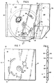
- FIG. 1 A partially broken away elevational view of a peanut applicator in operation according to the present invention, is shown in figure 1.
- An extrudate rope 100 moves from right to left as indicated by the arrows, in figure 1.
- the extrudate rope 100 is supported by a moving conveyor belt 201.
- the extrudate rope 100 passes beneath a rotating drum end member 3 which applies individual peanuts 601 to the top of the extrudate rope 100.
- a peanut hopper having a hopper back wall 710 and a slanted hopper rear wall 711 holds a peanut supply 600.
- the rotating drum end member 3 picks up-peanuts from the peanut hopper and rotates them to a postion at which they are applied to the top and sides of the extrudate rope 100.
- a flat end member outer wall 33 rotates with a cylindrical drum member 4 (which picks up peanuts as discussed hereunder).
- a cylindrical shaft body 11 is seen supporting the rotating drum end member 3 and the cylindrical drum member 4 for rotation.
- a shaft bore 98 in the rotating drum end member 3 receives the cylindrical shaft body 11.
- the rotating drum end member 3 and the cylindrical drum member 4 are in an enclosure formed by, as seen in figure 1, a top front wall plate edge 83, a top rear wall plate edge 193, and an end plate rear side 95.
- a top plate edge 91 of an end plate 7 is shown in the figure.
- extrudate rope 100 passes beneath the cylindrical drum member 4, individual peanuts 601 are applied to extrudate rope 100.
- the extrudate rope 100 is shown in figure 3 as being of a generally rectangular cross section, having a caramel coating 105 and a nougat' center 110.
- the extrudate rope 100 may be formed by any process, for example by co-extrusion of the caramel coating 105 and the nougat center 110, or in the alternative the nougat center 110 may be formed first by extrusion or by other means, and the caramel coating 105 applied later.
- FIG 2 is a top elevational view of the peanut applicator of figure 1.
- drive means and connections for vacuuming an air supply are shown in figure 2.
- a plurality of structural support members 907 are shown supporting the applicator assembly.
- the structural support members 907 are simply structural metal members which are welded, rivoted, or otherwise fastened to stationary portions of the peanut applicator, including a front wall plate 8 and at the rear to the end plate 7 and to the air supply end plate 6.
- the rear structural support members 907 may be connected to a rear wall plate 9 seen in figure 2.
- any support means may be used in the present invention, for example the peanut applicator apparatus could be suspended by attachment of a cable to any of the stationary parts (discussed hereunder).
- trust-racing could be used as well, or any other known type of structural support which can be anchored to any non-moving structures.
- the structural support members 907 are fixedly supported by a plurality of structural support bases 908, which in the usual case could be supports fastened to a floor or- maybe a part of the floor itself.
- An electric motor 902 shown in figure 2 is elevated above the conveyor belt 201.
- the electric motor 902 has an electrical cord 903 for supplying electrical power to the electric motor 902.
- the electric motor 902 has a motor output shaft 904.
- the motor output shaft 904 is connected, as is conventionally known, to a transverse bevel gear 905 which rotates a shaft angled downwardly from top to bottom in figure 2.
- the shaft of the transverse bevel gear 905 passes beneath the peanut hopper of figure 2 to a location where it rotates a chain drive pulley 909.
- the chain drive pulley 909 is connected by a chain passing beneath one of the structural support members 907.
- the chain drive 906 then connects about a Boston collar 120 which then rotates the peanut applicator moving parts.
- an electric motor 902 is shown as being used in the present invention, any type of rotary drive may be used.
- a pnuematic motor may.be used, or a steam-driven motor may be used, or any type of rotary drive contemplated as being within the scope of the present invention.
- the Boston collar 120 may be rotated directly by - any known rotary drive means.
- a pair of air supply hoses 931 are shown in figure 2 supplying air to portions of the interior of the cylindrical drum member 4, as explained further hereunder.
- a clamp 901 is shown in figure 2 connecting the peanut hopper to the rear wall plate 9 of the peanut applicator.
- the clamp 901 has a handle member which can be adjusted to tighten or loosen the clamp 901. Nonetheless, any type of connection may be made between the peanut supply hopper and the peanut applicator of the present invention.
- the peanut supply hopper may.be welded to the rear wall plate 9 of the peanut applicator, or it may be rivoted, bolted, glued, ultrasonically welded, or attached thereto by any means whatsoever.
- the peanut supply hopper has a width at least equal to that of the. groove formed in the cylindrical drum member 4 shown in figure 2.
- the peanut hopper should be at least as wide as the cylindrical drum member 4 itself and preferrably wider than the entire peanut applicator assembly so that constant refilling can be avoided.
- the height or depth of the peanut hopper is also generally arbitrary so long as a sufficient number of peanuts are supplied (as seen in the view of figure 1) to the cylindrical drum member 4 such that a sufficient number of individual peanuts 601 are available for deposition onto the extrudate rope 100.
- the peanut hopper is composed of a hopper back wall 710, to hopper side walls 700, and a threaded bores 620.
- the enclosure for the peanut hopper may have any arbitrary shape, such as cylindrical, spherical, triangular, or the like, so long as the enclosure, as seen in figure 1 having a slanted hopper rear wall 711, is sufficiently shaped to retain peanuts against the cylindrical drum member 4 without spalling or spilling of peanuts away from the peanut hopper.
- Figure 4 is an exploded view of the parts forming the peanut applicator assembly, but not including the parts for the peanut hopper portion of the peanut applicator.
- a front wall plate 8 is connectable to an end plate 7 and to an air supply end plate 6 to form a portion of a rigid enclosure of the rotating parts, which are the rotating drum end member 3, the cylindrical drum member 4, the shaft nut applicator rod 1, and both the near Boston collar 120 (as seen in- figure 4) and the far Boston collar 120.
- the enclosure is completed by assembly of the rear wall plate 9 to the edges of the air supply end plate 6 and the end plate 7.
- the stationary components include the enclosure members described above, as well as the hose connector 5, the air supply end plate 6, the stationary drum end members 2.
- Bolts connect stationary portions together, as suggested in the figures, as well as connecting the rotating drum end member 3 to the cylindrical drum member 4.
- the parts are further described in the remaining figures showing the individual components of he peanut applicator assembly. In figure 4, small details have been omitted in order to give a clear teaching of exactly how the components are assembled together in a perspective manner.
- Figure 5 is a side elevational view showing the peanut applicator assembly from the opposite side of that shown in figure 1, and generally with the near side same as that shown in figure 4.
- the peanut hopper is seen as having a hopper side wall 712, which is beneath the hopper side walls 700.
- the connection of the hose connector 5 is more clearly shown in relationship with a curvilinear slot 24.
- connection of the exterior facing plate surface 610 to the air supply end plate 6 is shown as being by a plurality of retaining bolts 720, only two of which are shown in figure 5, the remaining being indicated as being evenly spaced about a radius occupied by the two retaining bolts 720 shown.
- a first upstanding stationary wall 25 and a second upstanding stationary wall 26 is shown in dotted outline in figure 5, together with an air inlet passageway 290 shown in dotted outline in each one.
- FIG 5 Also shown in figure 5 is an air hose inlet location 941 and an air hose inlet locaton 942.
- the slots exposing a portion of the stationary drum end members 2 are seen in figure 5.
- the rear wall plate body 190 of the rear wall plate 9 is shown in dotted outline in figure 5.
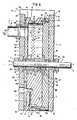
- FIG. 6 is a side sectional view taken along line 6-6 of figure 5.
- the air hose inlet location 941 is seen formed through the air supply end plate 6 in figure 6.
- the air hose inlet location 941 communicates with an air inlet passageway 290 which in turn communicates with an air supply bore 29 which in turn communicates with an air supply slot 28; all of - which are formed in the stationary drum end members 2.
- each of the air passages 42 pass adjacent to the air supply slot 28.
- pressurized air introduced into the air hose inlet location 941 passes through the stationary drum end members 2 and into and through the air passages 42. This air dislodges any peanuts which had been retained by. a vacuum applied to a side of the air passages 42.
- the second upstanding stationary wall 26 also has a similar air passageway there through, and is separated from the first upstanding stationary wall 25 shown in figure 6 by an arch of approximately 30 degrees.
- peanuts are held upon the cylindrical drum member 4 by the vacuum until such point as the peanuts directly overlie the extrudate rope 100, at which point pressurized air is applied to allow the peanuts 601 to adhere to the caramel coating 105.
- the second air passageway formed in the second upstanding stationary wall 26 dislodges peanuts at a location just before the bottom most wall of the peanut hopper is reached. At this location, the cylindrical drum member 4 again experiences at interior vacuum drawing and attaching peanuts to the. air passages 42 so as to draw them from the peanut hopper.
- a hub attaching member perimeter 34 is attached to the cylindrical shaft body 11 by means of a setscrew 399.
- the Boston collar 120 shown at either end of the shaft nut applicator rod 1 can also be attached by means of setscrews (not shown in figure 6).
- a bolt 470 is shown at the top and the bottom extent of the rotating drum end member 3 to affix it to the cylindrical drum member 4. Both of these members rotate together.
- the interior of the cylindrical drum member 4 is shown as having an interior cylindrical surface 44, which is seen in figure 6.
- the air passages 42 are also visible in the interior cylindrical surface 44.
- a portion of a curvilinear slot 24 is aligned with a vacuum outlet bore 61 formed in the air supply end plate 6.
- the hose connector 5 is aligned with the vacuum outlet bore 61 so as to communicate with the interior of cylindrical drum member 4.
- suction is applied from the interior of the cylindrical drum member 4 to each of the air passages 42.
- individual peanuts 601 are picked up by each of the individual air passages 42. This causes a precisely predetermined number of peanuts to be applied to the extrudate rope 100 as the extrudate rope 100 passes beneath the cylindrical drum member 4.
- the top of the front wall plate 8 is visible in figure 6 and is seen in elevational view.
- the rear wall plate 9 is not visible in figure 6. The other parts shown in figure 6 are discussed in greater detail hereunder, and are shown in the other figures.
- first upstanding stationary wall 25 remains motionless together with the stationary drum end members 2 and the air supply end plate 6. It is the cylindrical drum member 4 and the rotating drum end member 3 which rotate relative to the stationary drum end members 2.
- Figure 7 is a front elevational view of the air supply end plate 6.
- the attachment slots 62 are shown in their true shape; only two of the attachment slots 62 are shown, with six of the attachment slots 62 actually being provided spaced equangularly and also equadistantly from the center of the bore 68.
- the bore 68 is bored through the plate completely so as to be adapted to receive the shaft nut applicator rod 1.
- a rim 69 Surrounding the bore 68 is a rim 69. Between the rim 69 and the bore 68 is a shallow counterbore area which in figure 7 appears as an annular ring about the bore 68.
- the interior plate surface 60 is seen in figure 7, and has a pair of air inlet connection slots 63 shown in their true form in this figure.
- the air inlet connection slots 63 extend completely through the plate and are used to provide space for an air supply to pass through the air supply end plate 6.
- the slots are elongated so as to make close machining tolerances of the air inlet connection slots 63 unnecessary, and also to permit an adjustable relative inclination of the stationary drum end members 2 which is affixed to the air supply end plate 6 during operation.
- attachment slots 62 are also formed as slots, since the stationary drum end members 2 is fastened to the air supply end plate 6 by means of 6 bolts, the heads of which lie above the air supply end plate 6 in figure 7 and which are attached by insertion into threaded bores formed in the stationary drum end members 2.
- a vacuum outlet bore 61 is bored through the air supply end plate 6 to permit passage of air from the interior of the cylindrical drum member 4 into the vacuum outlet line.
- a pair of small threaded bores are disposed on opposite sides of the vacuum outlet bore 61, for permitting screw or bolt attachment of the hose connector 5 to the air supply end plate 6.
- the air supply end plate 6 has a top plate edge 64, a bottom plate edge 65, a first plate edge 66, and a'- second plate edge 67.
- the space between the bore 68 and the rim 69 is called an annular ledge 70.
- Figure 8 is a side elevational view of the air supply end plate 6 of figure 7.
- a plurality of threaded bores 620 are shown for receiving threaded fastening members such as bolts or. screws.
- a plurality of dowel holes 630 are shown in figure 8 for aligning the plate before insertion of threaded fasteners into the threaded bores 620.
- Figure 9 is a top elevational view of a end plate 7.
- the end plate front 90 is visible in figure 9 in frontal view.
- the end plate 7 has a top plate edge 91, a first side plate edge 92, a second side plate edge 94, and a bottom plate edge 93.
- the end plate 7 has a plurality of threaded bores 96 and a plurality of dowel holes 97, which are shown in figure 10.
- the threaded bores 96 and the dowel holes 97 are used for respectively fastening and aligning plate to the other members as shown in the preceding figures.
- the threaded bores 96 are adapted to receive a threaded member such as a screw or bolt for fastening purposes.
- Figure 10 is a side elevational view of the end plate 7 of figure 9. In this figure, the second side plate edge 94 is visible in frontal elevational view.
- FIG 11 is a front elevational view of the front wall plate 8.
- the wall front plate body 80 is visible in front elevational view.
- the front wall plate 8 has a top front wall plate edge 83, a bottom front wall plate edge 84, a left front wall plate edge 81, and a right front wall plate edge 82.
- the front wall plate 8 has a plurality of bores 85 and bores 86. Each of the bores is formed completely through the front wall plate 8.
- the left front wall plate edge 81 and the right front wall plate edge 82 are smooth and need not have any holes therein.
- FIG 12 is a front elevational view of a rear wall plate 9.
- the rear wall plate 9 has a rear wall plate body 190.
- the rear wall plate 9 also has a left rear wall plate edge 191, a right rear wall plate edge 192, a top rear wall plate edge 193, and a bottom rear plate edge 194.
- a plurality of bores 195 and of bores 196 are formed completely through the rear wall plate body 190.
- the bores are adapted to permit passage of a threaded member therethrough so that the rear wall plate 9 can be fastened, as by a screw to other members, as shown in figure 6. No other holes need be formed in the edges or in the front or rear surfaces of the rear wall plate body 190.
- threaded fasteners are used.
- any type of fastening means may be used, for example ultrasonic welding, glueing, use of adhesive, use of rivots, use of cable or string, or the like.
- Any type of fastening means for fastening parts together is comtemplated as being within the scope of the present invention.
- Figure 13 is a front elevational view of a rotating drum end member 3.
- the rotating drum end member 3 is adapted to be connected to, and rotate with, the cylindrical drum member 4.
- a plurality of bores 332 are formed through the rotating drum end member 3, on a portion of flat annular ledge 31.
- a perlmetral rim 331 is formed that is adapted to be snuggly received within the inner portion of the cylindrical drum member 4 to which the rotating drum end member 3 is to be attached.
- the rotating drum end member 3 has a flat inner surface 30, and a hub attaching member flat annular face 32 is formed on a cylindrical member fixedly attached to the flat inner surface 30 and to the hub-receiving bore 39.
- the hub-receiving bore 39 is adapted to receive the hub attaching member.
- the hub attaching member has a hub attaching member flat annular face 32 and a hub attaching member perimeter 34 as can be seen in figure 13.
- a key-shaped bore 37 is formed in the hub attaching - member.
- the hub attaching member has in the preferred embodiment a first setscrew threaded bore 35 and a second setscrew threaded bore 36.
- the first setscrew threaded bore 35 and the second setscrew threaded bore 36 are adapted to receive setscrews therein, for the purpose of fixedly attaching th entire rotating drum end member 3 to the shaft nut applicator rod 1.
- Figure 14 is a side sectional view of the rotating drum end member 3 of figure 13.
- all of the above-mentioned features are prominent as well as is the flat end member outer wall 33 which is the opposite surface to that shown in figure 13.
- a weld bead 38 is shown in both figures 13 and 14, and it is the weld bead 38 which fixedly attaches the hub attaching member to the main body of the rotating drum end member 3.
- FIG 15 is a side elevational view of the cylindrical drum member 4.
- the drum groove 41 can be clearly seen and has a plurality of air passages 42 formed therethrough.
- the drum groove 41 is adapted to closely abutt the surface of the extrudate rope 100 during opertion of the cylindrical drum member 4, so as to dispense peanuts onto the caramel coating 105.
- the cylindrical drum member 4 has a first rim portion 40 and a second rim portion 43; the first rim portion 40 is somewhat wider than the second rim portion'43.
- the cylindrical drum member 4 has a first drum side edge 45 and a second drum side edge 46.
- Figure 16 is a front elevational view of the cylindrical drum member 4, and shows the arrangement of two of the plurality of threaded bores 47.
- an interior cylindrical surface 44 is visible together with a dotted outline of the lower most extent of the drum groove 41.
- two of the air passages 42 are shown in dotted outline jn figure 16.
- Figure 17 is a side elevational view of the shaft nut applicator rod 1.
- the shaft nut applicator rod 1 has a first cylindrical shaft end 12 and a second cylindrical shaft end 13 the shaft nut applicator rod 1 is adapted to pass through and support the elements as seen in figure 6.
- Figure 18 is a front elevational view of the shaft nut applicator rod 1.
- the shaft nut applicator rod 1 has a circular perimeter, and the depth of the second slot edge 15 is seen in dotted outline.
- the first slot 16 has a upper first slot edge 14 and a lower first slot edge 18.
- the second slot 17 has an upper second slot edge 15 and a lower second slot edge 15.
- the shaft nut applicator rod 1 is shown as being a cylindrical solid body, it may be hollowed out, or it may peliginal, or even have an irregular shape, so long as the corresponding parts which must be fitted to it have corresponding shapes where entry of the shaft nut applicator rod 1 is permitted and where the other body is to rotate with the shaft nut applicator rod 1.
- the opening in the body through which the shaft nut applicator rod 1 passes need only be slightly larger than largest diameter of the shaft nut applicator rod 1.
- the shaft nut applicator rod 1 can be hollowed out, or formed from a honeycomb shape, so long as it is sufficiently strong to support and rotate the components of the peanut applicator assembly.
- the foregoing parts of the peanut applicator assembly may be manufactured preferrably of stainless steel or aluminum. Nonetheless, it is contemplated as being within the scope of the present invention to form the components of the peanut applicator assembly from any known material such as plastic, brass, wood, stone or the like.
- the shaft nut applicator rod 1 has a first slot 16 and second slot 17, any known means of attaching the parts which are to rotate together with the shaft nut applicator rod 1 may be used, for example by welding, ultrasonic welding, glueing, rivoting, use of adhesive, use of a shrink-fit between the compenents, r the like.
- Figure 19 is a side sectional view of the portion of the cylindrical drum member 4 indicated along 19-19 of figure 15. Here, the depth of the air passages, formed by internal bores 144 and air passages 42, are shown.
- the two internal bores 144 have relatively deeper penetrations into the thickness of the cylindrical drum member 4 due to the greater relative depth of the respective air passages 42 associated therewith.
- a plurality of central bores 145 are present as well, in this instance a single one of the central bores 145 are shown. The depth of the one of the- central bores 145 shown is much shorter than that of either of the internal bores 144.
- Each of the central bores 145 also is associated therewith one of the air passages 42.
- Figure 20 is a perspective view of the stationary drum end members 2 taken from the rear. In this view, particularly clearly shown are the first upstanding stationary wall 25, the second upstanding stationary wall 26, and the stationary cylindrical hub portion 22.
- the stationary cylindrical hub portion 22 has a stationary hub bore 23.
- a curvilinear slot 24 is shown formed through the body of the stationary drum end members 2.
- a disc 20 supports the first upstanding stationary wall 25, the second upstanding stationary wall 26, and the stationary cylindrical hub portion 22; these parts may be attached to the disc 20 by any known method, such as welding, ultrasonic bonding, by the use of threaded fastening members, or the like.
- a plurality of stationary end member mounting holes 21 are formed through the disc 20, and are spaced equiangularly and equidistantly from ihe center of the stationary cylindrical hub portion 22.
- the stationary end member mounting holes 21 are shown :n figure 20 as completely extending through the disc 20; each of the holes 21 is threaded and is adapted 03- receive a threaded fastening member.
- Figure 21 is a rear elevational view, which is taken from the front of figure 20 (which is itself ⁇ rear view).
- the true length of each of the first upstanding stationary wall 25 and the second upstanding stationary wall 26 are shown.
- the curvilinear slot 24 is shown in true dimensions also in figure 21.
- a transverse air supply bore 292 is shown in dotted outline in figure 21, and communicates with a air supply bore 29 (also shown in dotted outline).
- FIG 21 is shown in dotted outline a transverse air supply bore 292 which communicates with an air supply bore 29.
- the air supply bore 29 in turn communicates with an air supply slot 28.
- air under pressure is supplied to the transverse air supply bore 292 to thereby supply it to the air supply slot 28 by way of the air supply bore 29.
- This supply air path arrangement is formed in virtually identical fashion in both the first upstanding stationary wall 25 and in the- second upstanding stationary wall 26.
- the transverse air supply bore 292 penetrates the surface opposing that shown in figure 21 (shown more clearly in figure 23).
- first upstanding stationary wall 25 and the second upstanding stationary wall 26 are welded to the annular rim 27 as indicated in figure 21.
- Figure 22 is a side sectional view taken along the line 22-22 of figure 21.
- the stationary end member mounting holes 21 are shown clearly as passing entirely through the thickness of the stationary drum end members 2.
- a for shortened elevational view of the second upstanding stationary wall 26 is visible in figure 22.
- the end portion of the first upstanding stationary wall 25 is also visible in elevational view in figure 22.
- the air supply slot 28 is seen in figure 22 in dotted outline.
- the stationary cylindrical. hub portion 22 is in cross section, and the weld attachment points are shown in the figure.
- a raised annular rim 27 is visible on the right hand portion of the stationary drum end members 2 as seen in the figure. This portion is' adapted to engage with the annular ledge 70 of the air supply end plate 6. This serves to locate the plates - together such that they are entirely concentric.
- Figure 23 is a sectional view taken along the line 23-23 of figure 21.
- a section is taken through the middle of the first upstanding stationary wall 25, and shows clearly the outline of the air passageway.
- the transverse air supply bore 292 intersects the air supply bore 29, which in turn opens out into the air supply slot 28.
- air entering the transverse air supply bore 292 is communicated to the air supply slot 28.
- This air then would be in direct communication with the rotating body of the cylindrical drum member 4.
- the air passages 42 would receive air from the air supply slot 28, due to the close positioning of the air supply slot 28 to the air passages 42.
- Figure 24 is an end elevational view of the first upstanding stationary wall 25.
- the oblong oval outline of the air supply slot 28 is seen clearly. It is seen that the air supply bore 29 is circular.
- the stationary cylindrical hub portion 22 is visible in figure 24 and is behind the first upstanding stationary wall 25 in the figure, the sides of the stationary cylindrical hub portion 22 pertruding beyond either side of the first upstanding stationary wall 25.
- the curvilinear slot 24 is visible in figure 23.
- FIG 25 is a front elevational view of the hose - connector 5.
- the hose connector 5 has an interior hose connector bore 152, which is adapted to receive the shaft nut applicator rod 1.
- the hose connector bore 152 flares outwardly somewhat before intersecting the top surface 153 of the hose.connector 5.
- a pair of bores 154 are seen in figure 25, and are adapted to permit passage of a threaded fastener therethrough so that the hose connector 5 can be fastened to the front surface of the air supply end plate 6. This allows attachment of a vacuum hose, for example as by a friction fit by manually forcing the vacuum hose over the outer surface of the cylindrical hose connector member 151. Any connecting means may be used, however, between the vacuum hose and the hose connector 5.
- the hose may be glued to the hose connector 5, or the hose may be applied about the outer surface of the cylindrical hose connector member 151 and a metal band wrapped about the outer surface of the vacuum hose and then tightened as by a screw or other means, so as to fractionally retain the hose on the hose connector 5.
- Figure 26 is a sectional view of the hose connector 5 taken along line 24-24 of figure 25.
- the parts are numbered as in figure 25.
- the hose connector 5, as with. all of the other parts used, may be of any material that is sufficiently strong to enable a hose to be attached - to it, for example aluminum, steel, stainless steel, bronze, wood, ceramic material, or plastics are all contemplated as being within the scope of the present invention.
- Figure 27 is a view partially in section taken along line 27-27 of figure 1.
- the extrudate rope 100 in figure 27 is shown as being of circular cross-section, which is merely one of a virtually infinite number of variations contemplated as beinq usable with the present invention; in the preferred embodiment, the generally rectangular cross-section of the extrudate rope 100 as shown in figure 3 would be used .
- the groove of the cylindrical drum member 4 meets the extrudate rope 100.
- a pair of wooden blocks 810 These blocks underlie the conveyor belt 201 so as to create a region between them within which the extrudate rope 100 tends to remain centered.
- Beneath the conveyor belt 201 and the wooden blocks 810 is a support 108.
- the support 108 is conventionally made of steel or other metal, but may in fact be any support surface over which a conveyor belt may pass.
- vacuum hose hose and air pressure lines are shown. which are conventionally made of rubber or the like material, the vacuum hose may be formed of any type of conduit including stainless steel, plastic, ceramic material or the like. Furthermore, a director source of vacuum may be formed in any fashion from the location of the hose connector 5, as for example a strong fan of suitably small size may be used to draw air out of the cylindrical drum member 4 from the location at whichtaine- hose connector 5 is connected.
- the improved peanut applicator and system of the present invention is capable of achieving the above-enumerated objects and while preferred embodiments of the present invention have been disclosed, it will be understood that it is not limited thereto but may be otherwise embodied within the scope of the following claims.
Landscapes
- Life Sciences & Earth Sciences (AREA)
- Chemical & Material Sciences (AREA)
- Engineering & Computer Science (AREA)
- Food Science & Technology (AREA)
- Polymers & Plastics (AREA)
- Oil, Petroleum & Natural Gas (AREA)
- Seeds, Soups, And Other Foods (AREA)
- Manufacturing And Processing Devices For Dough (AREA)
- Confectionery (AREA)
Priority Applications (1)
| Application Number | Priority Date | Filing Date | Title |
|---|---|---|---|
| AT85401445T ATE39209T1 (de) | 1984-07-20 | 1985-07-15 | Erdnussablagerungsgeraet und ablagerungsverfahren zur konfektherstellung. |
Applications Claiming Priority (2)
| Application Number | Priority Date | Filing Date | Title |
|---|---|---|---|
| US06/632,823 US4760778A (en) | 1984-07-20 | 1984-07-20 | Peanut applicator and process of making a confectionery product |
| US632823 | 1984-07-20 |
Publications (2)
| Publication Number | Publication Date |
|---|---|
| EP0174221A1 true EP0174221A1 (de) | 1986-03-12 |
| EP0174221B1 EP0174221B1 (de) | 1988-12-14 |
Family
ID=24537096
Family Applications (1)
| Application Number | Title | Priority Date | Filing Date |
|---|---|---|---|
| EP85401445A Expired EP0174221B1 (de) | 1984-07-20 | 1985-07-15 | Erdnussablagerungsgerät und Ablagerungsverfahren zur Konfektherstellung |
Country Status (5)
| Country | Link |
|---|---|
| US (1) | US4760778A (de) |
| EP (1) | EP0174221B1 (de) |
| AT (1) | ATE39209T1 (de) |
| CA (1) | CA1251355A (de) |
| DE (1) | DE3566769D1 (de) |
Cited By (2)
| Publication number | Priority date | Publication date | Assignee | Title |
|---|---|---|---|---|
| EP0304570A3 (en) * | 1987-07-06 | 1989-10-18 | Sollich Gmbh & Co. Kg | Process and apparatus for the continuous production of hot confectionery paste subdivisible in sticks or bars |
| US4927004A (en) * | 1987-03-02 | 1990-05-22 | Etablissement Gersan | Feeder |
Families Citing this family (12)
| Publication number | Priority date | Publication date | Assignee | Title |
|---|---|---|---|---|
| US6424722B1 (en) * | 1997-01-13 | 2002-07-23 | Micro Ear Technology, Inc. | Portable system for programming hearing aids |
| US7787647B2 (en) | 1997-01-13 | 2010-08-31 | Micro Ear Technology, Inc. | Portable system for programming hearing aids |
| US6449662B1 (en) * | 1997-01-13 | 2002-09-10 | Micro Ear Technology, Inc. | System for programming hearing aids |
| US6537599B2 (en) | 1998-11-06 | 2003-03-25 | Mars, Incorporated | Method for making bakery goods and bakery goods prepared thereby |
| DK1252799T3 (da) | 2000-01-20 | 2012-01-23 | Starkey Lab Inc | Fremgangsmåde og apparat til tilpasning af høreapparater |
| US7275498B2 (en) | 2001-12-06 | 2007-10-02 | The Proctor 'gamble Company | Flowable solids dispensing apparatus and method of use |
| EP1593310B1 (de) * | 2004-05-07 | 2008-12-10 | Chocoladefabriken Lindt & Sprüngli (Schweiz) AG | Verfahren und Vorrichtung zum automatischen Einlegen von Lebensmittelstücken in ein Aufnahmeteil |
| CA2601662A1 (en) | 2006-09-18 | 2008-03-18 | Matthias Mullenborn | Wireless interface for programming hearing assistance devices |
| WO2008091706A1 (en) * | 2007-01-25 | 2008-07-31 | Radio Robots Llc | Remotely controlled system and method for the preparation of a user-defined food product or beverage |
| WO2010085612A2 (en) * | 2009-01-23 | 2010-07-29 | Mars, Incorporated | Product shaping method and apparatus |
| DE102010035105A1 (de) * | 2010-08-23 | 2012-02-23 | Bahlsen Gmbh & Co. Kg | Imbissprodukt und Verfahren zu dessen Herstellung |
| FR2987546B1 (fr) * | 2012-03-05 | 2015-06-05 | Vmi | Machine a petrir en continu une pate pour preparation boulangere ou patissiere telle que du pain de mie, et fraseur pour une telle machine |
Citations (6)
| Publication number | Priority date | Publication date | Assignee | Title |
|---|---|---|---|---|
| CH117155A (de) * | 1925-12-12 | 1927-01-03 | Buehler Ag Geb | Verfahren und Vorrichtung zum Entfernen von in fortschreitend bewegten Formplatten sich befindenden Formlingen. |
| GB689612A (en) * | 1951-04-24 | 1953-04-01 | Peter Paul Inc | Machine for depositing nuts on candy bars |
| US2837042A (en) * | 1956-01-03 | 1958-06-03 | Jr Claude C Laval | Cereal manufacturing device |
| US2868141A (en) * | 1950-08-23 | 1959-01-13 | Nat Biscuit Co | Sandwich machines |
| US3132847A (en) * | 1962-03-29 | 1964-05-12 | Cherry Burrell Corp | Apparatus for distributing fruit or nuts and the like into a flowable product |
| US4212609A (en) * | 1978-05-17 | 1980-07-15 | Fay Rudolph J | Method and apparatus for producing shaped and sized food articles |
Family Cites Families (12)
| Publication number | Priority date | Publication date | Assignee | Title |
|---|---|---|---|---|
| US2054319A (en) * | 1930-10-20 | 1936-09-15 | Electric Sorting Machine Compa | Sorting apparatus |
| US2032962A (en) * | 1934-11-22 | 1936-03-03 | Vogt Processes Inc | Fruit and nut feeding mechanism |
| US2152758A (en) * | 1937-04-05 | 1939-04-04 | Electric Sorting Machine Compa | Sorting machine |
| US2547516A (en) * | 1948-08-13 | 1951-04-03 | Peter Paul Inc | Machine for depositing nuts on candy bars |
| US2566712A (en) * | 1948-12-15 | 1951-09-04 | Peter Paul Inc | Machine for depositing nuts on candy bars |
| US2967493A (en) * | 1957-09-24 | 1961-01-10 | William S Cloud | Method and apparatus for applying nuts to candy |
| US3245360A (en) * | 1961-09-22 | 1966-04-12 | Pearson Candy Company | Apparatus for forming a confectionery product |
| US3156201A (en) * | 1962-11-07 | 1964-11-10 | Massey Ferguson Inc | Vacuum-type seed planter |
| JPS5211562A (en) * | 1975-07-16 | 1977-01-28 | Kyodo Denshi Kogyo Kk | Device of automatically feeding additives |
| US4239126A (en) * | 1977-11-30 | 1980-12-16 | Dobson Austin J | Seed sower having apertured pick-up member |
| JPS59198929A (ja) * | 1983-04-25 | 1984-11-10 | 増田 文彦 | 菓子生地等の表面への粉粒状物散布方法 |
| US4643905A (en) * | 1984-05-10 | 1987-02-17 | Vroman Foods, Inc. | Method for producing frozen confections including edible particulate material |
-
1984
- 1984-07-20 US US06/632,823 patent/US4760778A/en not_active Expired - Fee Related
-
1985
- 1985-06-28 CA CA000485803A patent/CA1251355A/en not_active Expired
- 1985-07-15 DE DE8585401445T patent/DE3566769D1/de not_active Expired
- 1985-07-15 EP EP85401445A patent/EP0174221B1/de not_active Expired
- 1985-07-15 AT AT85401445T patent/ATE39209T1/de not_active IP Right Cessation
Patent Citations (6)
| Publication number | Priority date | Publication date | Assignee | Title |
|---|---|---|---|---|
| CH117155A (de) * | 1925-12-12 | 1927-01-03 | Buehler Ag Geb | Verfahren und Vorrichtung zum Entfernen von in fortschreitend bewegten Formplatten sich befindenden Formlingen. |
| US2868141A (en) * | 1950-08-23 | 1959-01-13 | Nat Biscuit Co | Sandwich machines |
| GB689612A (en) * | 1951-04-24 | 1953-04-01 | Peter Paul Inc | Machine for depositing nuts on candy bars |
| US2837042A (en) * | 1956-01-03 | 1958-06-03 | Jr Claude C Laval | Cereal manufacturing device |
| US3132847A (en) * | 1962-03-29 | 1964-05-12 | Cherry Burrell Corp | Apparatus for distributing fruit or nuts and the like into a flowable product |
| US4212609A (en) * | 1978-05-17 | 1980-07-15 | Fay Rudolph J | Method and apparatus for producing shaped and sized food articles |
Cited By (2)
| Publication number | Priority date | Publication date | Assignee | Title |
|---|---|---|---|---|
| US4927004A (en) * | 1987-03-02 | 1990-05-22 | Etablissement Gersan | Feeder |
| EP0304570A3 (en) * | 1987-07-06 | 1989-10-18 | Sollich Gmbh & Co. Kg | Process and apparatus for the continuous production of hot confectionery paste subdivisible in sticks or bars |
Also Published As
| Publication number | Publication date |
|---|---|
| US4760778A (en) | 1988-08-02 |
| DE3566769D1 (en) | 1989-01-19 |
| CA1251355A (en) | 1989-03-21 |
| EP0174221B1 (de) | 1988-12-14 |
| ATE39209T1 (de) | 1988-12-15 |
Similar Documents
| Publication | Publication Date | Title |
|---|---|---|
| US4851248A (en) | Process of making a confectionery product | |
| EP0174221A1 (de) | Erdnussablagerungsgerät und Ablagerungsverfahren zur Konfektherstellung | |
| RU2678426C2 (ru) | Ультразвуковое ротационное формование | |
| US5603965A (en) | Apparatus for co-distributing confection products | |
| CA2683659C (en) | Ribbon cutter apparatus and method for making sandwich baked goods | |
| KR102082543B1 (ko) | 식품의 바닥부를 코팅하기 위한 시스템 및 방법 | |
| US3036533A (en) | Method and apparatus for coating food articles | |
| US6520111B2 (en) | Rotary drum seeder | |
| US3717752A (en) | Particle spraying device | |
| US4925689A (en) | Method for producing frozen confections | |
| US5031567A (en) | Apparatus for preparing portions of paste-form products | |
| US4537121A (en) | Apparatus for the manufacture of ice cream sandwiches | |
| US4715275A (en) | Apparatus for producing frozen confections including edible particulate material | |
| US2115969A (en) | Apparatus for producing peanut coated candies | |
| US3363586A (en) | Method and apparatus for producing decorated confections | |
| US4212617A (en) | Apparatus for producing a flow of short cheese strands | |
| CA1247937A (en) | Method and apparatus for producing frozen confections | |
| US5931086A (en) | Apparatus for the assembly of sandwich products | |
| US4962699A (en) | Distributing apparatus | |
| BE894208A (fr) | Produits de confiserie composites, et procede et appareillage pour leur preparation | |
| JPH0346097B2 (de) | ||
| JPS60172276A (ja) | 流動性食品の成形方法及び装置 | |
| BE1029174B1 (nl) | Inrichting voor het bestrijken van vierkante gebakjes | |
| US3257041A (en) | Device for dispensing pulverulent material | |
| JP3379722B2 (ja) | スティックレス型冷菓の製造方法及び製造装置 |
Legal Events
| Date | Code | Title | Description |
|---|---|---|---|
| PUAI | Public reference made under article 153(3) epc to a published international application that has entered the european phase |
Free format text: ORIGINAL CODE: 0009012 |
|
| AK | Designated contracting states |
Kind code of ref document: A1 Designated state(s): AT BE CH DE FR GB IT LI LU NL SE |
|
| 17P | Request for examination filed |
Effective date: 19860424 |
|
| 17Q | First examination report despatched |
Effective date: 19861223 |
|
| GRAA | (expected) grant |
Free format text: ORIGINAL CODE: 0009210 |
|
| AK | Designated contracting states |
Kind code of ref document: B1 Designated state(s): AT BE CH DE FR GB IT LI LU NL SE |
|
| REF | Corresponds to: |
Ref document number: 39209 Country of ref document: AT Date of ref document: 19881215 Kind code of ref document: T |
|
| ITF | It: translation for a ep patent filed | ||
| REF | Corresponds to: |
Ref document number: 3566769 Country of ref document: DE Date of ref document: 19890119 |
|
| ET | Fr: translation filed | ||
| PLBE | No opposition filed within time limit |
Free format text: ORIGINAL CODE: 0009261 |
|
| STAA | Information on the status of an ep patent application or granted ep patent |
Free format text: STATUS: NO OPPOSITION FILED WITHIN TIME LIMIT |
|
| 26N | No opposition filed | ||
| ITPR | It: changes in ownership of a european patent |
Owner name: CESSIONE;SOCIETE' DES PRODUCTS NESTLE' S.A. |
|
| REG | Reference to a national code |
Ref country code: CH Ref legal event code: PUE Owner name: SOCIETE DES PRODUITS NESTLE S.A. |
|
| REG | Reference to a national code |
Ref country code: FR Ref legal event code: TP |
|
| REG | Reference to a national code |
Ref country code: GB Ref legal event code: 732 |
|
| NLS | Nl: assignments of ep-patents |
Owner name: SOCIETE DES PRODUITS NESTLE S.A. TE VEVEY, ZWITSER |
|
| EPTA | Lu: last paid annual fee | ||
| ITTA | It: last paid annual fee | ||
| EAL | Se: european patent in force in sweden |
Ref document number: 85401445.3 |
|
| PGFP | Annual fee paid to national office [announced via postgrant information from national office to epo] |
Ref country code: LU Payment date: 19960701 Year of fee payment: 12 |
|
| PGFP | Annual fee paid to national office [announced via postgrant information from national office to epo] |
Ref country code: GB Payment date: 19960708 Year of fee payment: 12 |
|
| PGFP | Annual fee paid to national office [announced via postgrant information from national office to epo] |
Ref country code: FR Payment date: 19960709 Year of fee payment: 12 |
|
| PGFP | Annual fee paid to national office [announced via postgrant information from national office to epo] |
Ref country code: AT Payment date: 19960711 Year of fee payment: 12 |
|
| PGFP | Annual fee paid to national office [announced via postgrant information from national office to epo] |
Ref country code: SE Payment date: 19960717 Year of fee payment: 12 |
|
| PGFP | Annual fee paid to national office [announced via postgrant information from national office to epo] |
Ref country code: DE Payment date: 19960722 Year of fee payment: 12 Ref country code: CH Payment date: 19960722 Year of fee payment: 12 |
|
| PGFP | Annual fee paid to national office [announced via postgrant information from national office to epo] |
Ref country code: NL Payment date: 19960729 Year of fee payment: 12 |
|
| PGFP | Annual fee paid to national office [announced via postgrant information from national office to epo] |
Ref country code: BE Payment date: 19960828 Year of fee payment: 12 |
|
| PG25 | Lapsed in a contracting state [announced via postgrant information from national office to epo] |
Ref country code: LU Free format text: LAPSE BECAUSE OF NON-PAYMENT OF DUE FEES Effective date: 19970715 Ref country code: GB Free format text: LAPSE BECAUSE OF NON-PAYMENT OF DUE FEES Effective date: 19970715 Ref country code: AT Free format text: LAPSE BECAUSE OF NON-PAYMENT OF DUE FEES Effective date: 19970715 |
|
| PG25 | Lapsed in a contracting state [announced via postgrant information from national office to epo] |
Ref country code: SE Effective date: 19970716 |
|
| PG25 | Lapsed in a contracting state [announced via postgrant information from national office to epo] |
Ref country code: LI Free format text: LAPSE BECAUSE OF NON-PAYMENT OF DUE FEES Effective date: 19970731 Ref country code: CH Free format text: LAPSE BECAUSE OF NON-PAYMENT OF DUE FEES Effective date: 19970731 Ref country code: BE Free format text: LAPSE BECAUSE OF NON-PAYMENT OF DUE FEES Effective date: 19970731 |
|
| BERE | Be: lapsed |
Owner name: SOC. DES PRODUITS NESTLE S.A. Effective date: 19970731 |
|
| PG25 | Lapsed in a contracting state [announced via postgrant information from national office to epo] |
Ref country code: NL Free format text: LAPSE BECAUSE OF NON-PAYMENT OF DUE FEES Effective date: 19980201 |
|
| GBPC | Gb: european patent ceased through non-payment of renewal fee |
Effective date: 19970715 |
|
| REG | Reference to a national code |
Ref country code: CH Ref legal event code: PL |
|
| PG25 | Lapsed in a contracting state [announced via postgrant information from national office to epo] |
Ref country code: FR Free format text: LAPSE BECAUSE OF NON-PAYMENT OF DUE FEES Effective date: 19980331 |
|
| NLV4 | Nl: lapsed or anulled due to non-payment of the annual fee |
Effective date: 19980201 |
|
| PG25 | Lapsed in a contracting state [announced via postgrant information from national office to epo] |
Ref country code: DE Free format text: LAPSE BECAUSE OF NON-PAYMENT OF DUE FEES Effective date: 19980401 |
|
| EUG | Se: european patent has lapsed |
Ref document number: 85401445.3 |
|
| REG | Reference to a national code |
Ref country code: FR Ref legal event code: ST |