EP0174286B1 - Turbogenerator usw. mit einer Schaufel-Winkel-Einstelleinrichtung für eine hydraulische Turbine oder Pumpe - Google Patents
Turbogenerator usw. mit einer Schaufel-Winkel-Einstelleinrichtung für eine hydraulische Turbine oder Pumpe Download PDFInfo
- Publication number
- EP0174286B1 EP0174286B1 EP85850264A EP85850264A EP0174286B1 EP 0174286 B1 EP0174286 B1 EP 0174286B1 EP 85850264 A EP85850264 A EP 85850264A EP 85850264 A EP85850264 A EP 85850264A EP 0174286 B1 EP0174286 B1 EP 0174286B1
- Authority
- EP
- European Patent Office
- Prior art keywords
- pump
- turbine
- hub
- vanes
- adjusting
- Prior art date
- Legal status (The legal status is an assumption and is not a legal conclusion. Google has not performed a legal analysis and makes no representation as to the accuracy of the status listed.)
- Expired - Lifetime
Links
- ZZUFCTLCJUWOSV-UHFFFAOYSA-N furosemide Chemical compound C1=C(Cl)C(S(=O)(=O)N)=CC(C(O)=O)=C1NCC1=CC=CO1 ZZUFCTLCJUWOSV-UHFFFAOYSA-N 0.000 title claims abstract description 4
- 238000005192 partition Methods 0.000 claims 1
- 238000011144 upstream manufacturing Methods 0.000 claims 1
- XLYOFNOQVPJJNP-UHFFFAOYSA-N water Substances O XLYOFNOQVPJJNP-UHFFFAOYSA-N 0.000 abstract description 9
- 230000005540 biological transmission Effects 0.000 abstract 1
- 230000007246 mechanism Effects 0.000 description 3
- 230000009347 mechanical transmission Effects 0.000 description 2
- 238000010276 construction Methods 0.000 description 1
- 238000012423 maintenance Methods 0.000 description 1
- 238000005381 potential energy Methods 0.000 description 1
- 230000007704 transition Effects 0.000 description 1
Images
Classifications
-
- F—MECHANICAL ENGINEERING; LIGHTING; HEATING; WEAPONS; BLASTING
- F03—MACHINES OR ENGINES FOR LIQUIDS; WIND, SPRING, OR WEIGHT MOTORS; PRODUCING MECHANICAL POWER OR A REACTIVE PROPULSIVE THRUST, NOT OTHERWISE PROVIDED FOR
- F03B—MACHINES OR ENGINES FOR LIQUIDS
- F03B3/00—Machines or engines of reaction type; Parts or details peculiar thereto
- F03B3/12—Blades; Blade-carrying rotors
- F03B3/14—Rotors having adjustable blades
- F03B3/145—Mechanisms for adjusting the blades
-
- F—MECHANICAL ENGINEERING; LIGHTING; HEATING; WEAPONS; BLASTING
- F05—INDEXING SCHEMES RELATING TO ENGINES OR PUMPS IN VARIOUS SUBCLASSES OF CLASSES F01-F04
- F05B—INDEXING SCHEME RELATING TO WIND, SPRING, WEIGHT, INERTIA OR LIKE MOTORS, TO MACHINES OR ENGINES FOR LIQUIDS COVERED BY SUBCLASSES F03B, F03D AND F03G
- F05B2260/00—Function
- F05B2260/40—Transmission of power
- F05B2260/406—Transmission of power through hydraulic systems
-
- F—MECHANICAL ENGINEERING; LIGHTING; HEATING; WEAPONS; BLASTING
- F05—INDEXING SCHEMES RELATING TO ENGINES OR PUMPS IN VARIOUS SUBCLASSES OF CLASSES F01-F04
- F05B—INDEXING SCHEME RELATING TO WIND, SPRING, WEIGHT, INERTIA OR LIKE MOTORS, TO MACHINES OR ENGINES FOR LIQUIDS COVERED BY SUBCLASSES F03B, F03D AND F03G
- F05B2260/00—Function
- F05B2260/70—Adjusting of angle of incidence or attack of rotating blades
- F05B2260/76—Adjusting of angle of incidence or attack of rotating blades the adjusting mechanism using auxiliary power sources
-
- Y—GENERAL TAGGING OF NEW TECHNOLOGICAL DEVELOPMENTS; GENERAL TAGGING OF CROSS-SECTIONAL TECHNOLOGIES SPANNING OVER SEVERAL SECTIONS OF THE IPC; TECHNICAL SUBJECTS COVERED BY FORMER USPC CROSS-REFERENCE ART COLLECTIONS [XRACs] AND DIGESTS
- Y02—TECHNOLOGIES OR APPLICATIONS FOR MITIGATION OR ADAPTATION AGAINST CLIMATE CHANGE
- Y02E—REDUCTION OF GREENHOUSE GAS [GHG] EMISSIONS, RELATED TO ENERGY GENERATION, TRANSMISSION OR DISTRIBUTION
- Y02E10/00—Energy generation through renewable energy sources
- Y02E10/20—Hydro energy
Definitions
- This invention concerns a hydroturbine-generator or an electro motor-pump assembly according to the preamble of claim 1.
- the hydro turbine comprises a rotating hub provided with a number of vanes and arranged in a tube or the like for flowing water.
- the rotary energy obtained is transmitted to a generator for producing electric current.
- the rotary energy generated is of course entirely depending on the amount of flowing water as well as its potential energy, head.
- the water amount may vary considerably which means that the turbine will operate with different volume flows at different times.
- the turbine is designed to have a maximum efficiency at a certain flow and a certain head, the energy of the water will be utilised more or less well.
- vanes adjustable which means that the vane angle with relation to the water flow may be varied, there is a possibility to optimise the efficiency within a relatively wide range of water amounts.
- FR-A-1180324 deals with a turbine generator of a conventional type which is mounted on site and must be demounted in pieces for service etc.
- the non-rotating fairing behind the hub of the turbine is attached to the lower tube. This means that when demounting, the rotating unit must be parted from the non-rotating unit and hoisted up. Then the service man must go down into the tube to reach the remaining parts.
- the entire unit can be taken up from the site for service.
- the entire unit includes rotating and non-rotating parts.
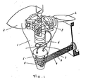
- the invention is more closely described below with reference to the enclosed drawing which shows a partly cut view of a part of the hydraulic part is a submersible energy unit which also includes a generator.
- FIG. 1 stands for a hub and 2 for vanes turnably attached to the hub.
- 3 stands for mechanical transmission means, 4 a hydraulic cylinder, 5 a stationary fairing behind 6 a rotary part belonging to the hub 7,8 and 9 finally stand for pressure medium tubes.
- the entire machine is designed as a single unit easily mountable in a perferably vertical tube or shaft for the flowing water.
- the device according to this invention makes this possible in an easy and reliable way.
- Pressure medium is brought from a medium source via the tubes 7 and 8 into the stationary fairing, 5 behind the rotary unit.
- Said fairing is connected to the rotating part 6, the transition being sealed by a mechanical real device. This means that the rotary unit is submersible like all other parts in the device.
- the unit consisting of the fairing 5 and the associated rotating part 6 may be an integrated part of the hub or its cone 1 or be attached in the latter.
- the pressure impulses are transmitted in a hydraulic cylinder 4, which also may be an integrated part of the hub.
- the movement of the hydraulic cylinder is transmitted via a mechanism 3 comprising links and slide guides to the attachments of the vanes 2 in the hub.
- the building of the control mechanism has several great advantages.
- the equipment may be designed independent of other means, such as a gear box, which may be mounted between the turbine and the generator.
- the hydraulic control of the vane adjustment is variable and very exact.
- the location in the bottom part of the hub cone means in addition, that a drainage may be very easily obtained through the tube 9. Another advantage is that all reaction forces are internally absorbed.
Landscapes
- Engineering & Computer Science (AREA)
- Chemical & Material Sciences (AREA)
- Combustion & Propulsion (AREA)
- Mechanical Engineering (AREA)
- General Engineering & Computer Science (AREA)
- Hydraulic Turbines (AREA)
- Structures Of Non-Positive Displacement Pumps (AREA)
- Other Liquid Machine Or Engine Such As Wave Power Use (AREA)
- Nitrogen And Oxygen Or Sulfur-Condensed Heterocyclic Ring Systems (AREA)
- Pharmaceuticals Containing Other Organic And Inorganic Compounds (AREA)
- Transition And Organic Metals Composition Catalysts For Addition Polymerization (AREA)
- Hydraulic Motors (AREA)
- Control Of Vehicle Engines Or Engines For Specific Uses (AREA)
Claims (2)
Priority Applications (1)
| Application Number | Priority Date | Filing Date | Title |
|---|---|---|---|
| AT85850264T ATE57993T1 (de) | 1984-09-05 | 1985-08-23 | Turbogenerator usw. mit einer schaufel-winkeleinstelleinrichtung fuer eine hydraulische turbine oder pumpe. |
Applications Claiming Priority (2)
| Application Number | Priority Date | Filing Date | Title |
|---|---|---|---|
| SE8404443A SE450278B (sv) | 1984-09-05 | 1984-09-05 | Anordning for instellning av skovelbladsvinklarna i en vattenturbin |
| SE8404443 | 1984-09-05 |
Publications (2)
| Publication Number | Publication Date |
|---|---|
| EP0174286A1 EP0174286A1 (de) | 1986-03-12 |
| EP0174286B1 true EP0174286B1 (de) | 1990-10-31 |
Family
ID=20356925
Family Applications (1)
| Application Number | Title | Priority Date | Filing Date |
|---|---|---|---|
| EP85850264A Expired - Lifetime EP0174286B1 (de) | 1984-09-05 | 1985-08-23 | Turbogenerator usw. mit einer Schaufel-Winkel-Einstelleinrichtung für eine hydraulische Turbine oder Pumpe |
Country Status (7)
| Country | Link |
|---|---|
| EP (1) | EP0174286B1 (de) |
| JP (1) | JPS6198972A (de) |
| AT (1) | ATE57993T1 (de) |
| CA (1) | CA1249201A (de) |
| DE (1) | DE3580328D1 (de) |
| NO (1) | NO853437L (de) |
| SE (1) | SE450278B (de) |
Families Citing this family (5)
| Publication number | Priority date | Publication date | Assignee | Title |
|---|---|---|---|---|
| SE455629B (sv) * | 1986-11-25 | 1988-07-25 | Flygt Ab | Rotationskoppling |
| DE4306140A1 (de) * | 1993-02-27 | 1994-09-01 | Klein Schanzlin & Becker Ag | Hydraulische Verstelleinrichtung |
| DE4446624A1 (de) * | 1994-12-24 | 1996-06-27 | Klein Schanzlin & Becker Ag | Verstellpropeller |
| DE4446622A1 (de) * | 1994-12-24 | 1996-06-27 | Klein Schanzlin & Becker Ag | Verstellpropeller mit darin angeordnetem Verstellmechanismus |
| CN107246381B (zh) * | 2017-08-04 | 2020-01-14 | 广东力源工程技术有限公司 | 一种节能的流量调节装置 |
Family Cites Families (8)
| Publication number | Priority date | Publication date | Assignee | Title |
|---|---|---|---|---|
| US1950776A (en) * | 1932-12-15 | 1934-03-13 | James Leffel & Company | Hydraulic turbine |
| CH170547A (de) * | 1933-10-04 | 1934-07-15 | Escher Wyss Maschf Ag | Kreiselmaschine, insbesondere Wasserturbine, mit hohler Welle und beweglichen Laufradschaufeln. |
| FR61496E (fr) * | 1951-03-30 | 1955-05-04 | Electricite De France | Dispositif pour la régulation automatique de groupes hydroélectriques |
| CH345622A (de) * | 1956-09-10 | 1960-03-31 | Escher Wyss Ag | Laufrad für Turbinen oder Pumpen mit drehbaren Schaufeln, insbesondere für grossen Verstellbereich |
| US3140074A (en) * | 1962-11-29 | 1964-07-07 | Dominion Eng Works Ltd | Fluid machines |
| GB1103221A (en) * | 1963-12-05 | 1968-02-14 | English Electric Co Ltd | Improvements in and relating to hydraulic turbines and pump/turbines |
| US3785747A (en) * | 1972-11-10 | 1974-01-15 | Allis Chalmers | Axial flow hydraulic turbine generator installation |
| JPS56151299A (en) * | 1980-04-25 | 1981-11-24 | Hitachi Ltd | Adjusting device for movable vane of vertical-shaft pump |
-
1984
- 1984-09-05 SE SE8404443A patent/SE450278B/sv not_active IP Right Cessation
-
1985
- 1985-08-02 JP JP60171005A patent/JPS6198972A/ja active Pending
- 1985-08-23 EP EP85850264A patent/EP0174286B1/de not_active Expired - Lifetime
- 1985-08-23 AT AT85850264T patent/ATE57993T1/de not_active IP Right Cessation
- 1985-08-23 DE DE8585850264T patent/DE3580328D1/de not_active Expired - Fee Related
- 1985-08-29 CA CA000489701A patent/CA1249201A/en not_active Expired
- 1985-09-02 NO NO853437A patent/NO853437L/no unknown
Also Published As
| Publication number | Publication date |
|---|---|
| EP0174286A1 (de) | 1986-03-12 |
| JPS6198972A (ja) | 1986-05-17 |
| DE3580328D1 (de) | 1990-12-06 |
| SE450278B (sv) | 1987-06-15 |
| NO853437L (no) | 1986-03-06 |
| SE8404443D0 (sv) | 1984-09-05 |
| ATE57993T1 (de) | 1990-11-15 |
| SE8404443L (sv) | 1986-03-06 |
| CA1249201A (en) | 1989-01-24 |
Similar Documents
| Publication | Publication Date | Title |
|---|---|---|
| US4629904A (en) | Micro-hydroelectric power plant | |
| US4258271A (en) | Power converter and method | |
| US4392063A (en) | Turbine installation comprising a turbine installed in a duct | |
| EP0104034A1 (de) | Windturbine | |
| US3785747A (en) | Axial flow hydraulic turbine generator installation | |
| US4496282A (en) | Reversible two-stage hydraulic machine | |
| US5905311A (en) | Integrated hydroelectric unit | |
| AU2002325610B2 (en) | Wind power plant for generating energy | |
| EP0274368B1 (de) | Rotierende Abdichtung | |
| EP0174286A1 (de) | Turbogenerator usw. mit einer Schaufel-Winkel-Einstelleinrichtung für eine hydraulische Turbine oder Pumpe | |
| US20040197215A1 (en) | Method of converting storage pumps into reversible pump-turbines | |
| DE3015756A1 (de) | Windturbine | |
| EP1131556B1 (de) | Verfahren zum betrieb einer wasserturbine | |
| CN2534383Y (zh) | 节能式水力发电装置 | |
| US4955789A (en) | Duplex turbine replacement unit and method | |
| MXPA04005531A (es) | Turbina a impulso, particularmente del tipo reversible. | |
| GB976695A (en) | Improvements in or relating to hydraulic installations comprising a turbine and a pump | |
| EP1299642B1 (de) | HYDRAULISCHE STRöMUNGSMASCHINE | |
| US3936224A (en) | Power turbine | |
| JPH04121459A (ja) | 低流速用水車装置 | |
| RU1813915C (ru) | Ветродвигатель | |
| SU1701974A1 (ru) | Гидроэлектростанци | |
| RU2193104C1 (ru) | Гидротурбина с затвором | |
| RU2191919C1 (ru) | Гидротурбина | |
| RU2005906C1 (ru) | Способ получения электроэнергии и гидроветровое устройство для его осуществления |
Legal Events
| Date | Code | Title | Description |
|---|---|---|---|
| PUAI | Public reference made under article 153(3) epc to a published international application that has entered the european phase |
Free format text: ORIGINAL CODE: 0009012 |
|
| 17P | Request for examination filed |
Effective date: 19850902 |
|
| AK | Designated contracting states |
Kind code of ref document: A1 Designated state(s): AT CH DE FR GB IT LI SE |
|
| 17Q | First examination report despatched |
Effective date: 19880301 |
|
| GRAA | (expected) grant |
Free format text: ORIGINAL CODE: 0009210 |
|
| AK | Designated contracting states |
Kind code of ref document: B1 Designated state(s): AT CH DE FR GB IT LI SE |
|
| PG25 | Lapsed in a contracting state [announced via postgrant information from national office to epo] |
Ref country code: SE Effective date: 19901031 |
|
| REF | Corresponds to: |
Ref document number: 57993 Country of ref document: AT Date of ref document: 19901115 Kind code of ref document: T |
|
| REF | Corresponds to: |
Ref document number: 3580328 Country of ref document: DE Date of ref document: 19901206 |
|
| ITF | It: translation for a ep patent filed | ||
| ET | Fr: translation filed | ||
| PLBE | No opposition filed within time limit |
Free format text: ORIGINAL CODE: 0009261 |
|
| STAA | Information on the status of an ep patent application or granted ep patent |
Free format text: STATUS: NO OPPOSITION FILED WITHIN TIME LIMIT |
|
| 26N | No opposition filed | ||
| ITTA | It: last paid annual fee | ||
| PGFP | Annual fee paid to national office [announced via postgrant information from national office to epo] |
Ref country code: GB Payment date: 19960814 Year of fee payment: 12 |
|
| PGFP | Annual fee paid to national office [announced via postgrant information from national office to epo] |
Ref country code: AT Payment date: 19960827 Year of fee payment: 12 |
|
| PGFP | Annual fee paid to national office [announced via postgrant information from national office to epo] |
Ref country code: FR Payment date: 19960829 Year of fee payment: 12 |
|
| PGFP | Annual fee paid to national office [announced via postgrant information from national office to epo] |
Ref country code: CH Payment date: 19960925 Year of fee payment: 12 |
|
| PGFP | Annual fee paid to national office [announced via postgrant information from national office to epo] |
Ref country code: DE Payment date: 19961024 Year of fee payment: 12 |
|
| PG25 | Lapsed in a contracting state [announced via postgrant information from national office to epo] |
Ref country code: GB Free format text: LAPSE BECAUSE OF NON-PAYMENT OF DUE FEES Effective date: 19970823 Ref country code: AT Free format text: LAPSE BECAUSE OF NON-PAYMENT OF DUE FEES Effective date: 19970823 |
|
| PG25 | Lapsed in a contracting state [announced via postgrant information from national office to epo] |
Ref country code: LI Free format text: LAPSE BECAUSE OF NON-PAYMENT OF DUE FEES Effective date: 19970831 Ref country code: CH Free format text: LAPSE BECAUSE OF NON-PAYMENT OF DUE FEES Effective date: 19970831 |
|
| GBPC | Gb: european patent ceased through non-payment of renewal fee |
Effective date: 19970823 |
|
| REG | Reference to a national code |
Ref country code: CH Ref legal event code: PL |
|
| PG25 | Lapsed in a contracting state [announced via postgrant information from national office to epo] |
Ref country code: FR Free format text: LAPSE BECAUSE OF NON-PAYMENT OF DUE FEES Effective date: 19980430 |
|
| PG25 | Lapsed in a contracting state [announced via postgrant information from national office to epo] |
Ref country code: DE Free format text: LAPSE BECAUSE OF NON-PAYMENT OF DUE FEES Effective date: 19980501 |
|
| REG | Reference to a national code |
Ref country code: FR Ref legal event code: ST |