EP0174385B1 - Dispositif de support pour conducteurs électriques - Google Patents
Dispositif de support pour conducteurs électriques Download PDFInfo
- Publication number
- EP0174385B1 EP0174385B1 EP84110862A EP84110862A EP0174385B1 EP 0174385 B1 EP0174385 B1 EP 0174385B1 EP 84110862 A EP84110862 A EP 84110862A EP 84110862 A EP84110862 A EP 84110862A EP 0174385 B1 EP0174385 B1 EP 0174385B1
- Authority
- EP
- European Patent Office
- Prior art keywords
- carriers
- insulating material
- longitudinal
- transverse
- outer face
- Prior art date
- Legal status (The legal status is an assumption and is not a legal conclusion. Google has not performed a legal analysis and makes no representation as to the accuracy of the status listed.)
- Expired
Links
- 239000004020 conductor Substances 0.000 title claims abstract 19
- 239000000969 carrier Substances 0.000 claims abstract description 35
- 239000011810 insulating material Substances 0.000 claims abstract description 30
- 238000010276 construction Methods 0.000 claims abstract 3
- 239000012530 fluid Substances 0.000 abstract 1
- 238000005452 bending Methods 0.000 description 1
- 230000015572 biosynthetic process Effects 0.000 description 1
- 238000006243 chemical reaction Methods 0.000 description 1
- 230000001419 dependent effect Effects 0.000 description 1
- 239000007788 liquid Substances 0.000 description 1
- 239000000463 material Substances 0.000 description 1
- 238000012986 modification Methods 0.000 description 1
- 230000004048 modification Effects 0.000 description 1
- 239000011120 plywood Substances 0.000 description 1
- 230000001105 regulatory effect Effects 0.000 description 1
- 239000002023 wood Substances 0.000 description 1
Images


Classifications
-
- F—MECHANICAL ENGINEERING; LIGHTING; HEATING; WEAPONS; BLASTING
- F16—ENGINEERING ELEMENTS AND UNITS; GENERAL MEASURES FOR PRODUCING AND MAINTAINING EFFECTIVE FUNCTIONING OF MACHINES OR INSTALLATIONS; THERMAL INSULATION IN GENERAL
- F16B—DEVICES FOR FASTENING OR SECURING CONSTRUCTIONAL ELEMENTS OR MACHINE PARTS TOGETHER, e.g. NAILS, BOLTS, CIRCLIPS, CLAMPS, CLIPS OR WEDGES; JOINTS OR JOINTING
- F16B7/00—Connections of rods or tubes, e.g. of non-circular section, mutually, including resilient connections
- F16B7/04—Clamping or clipping connections
- F16B7/044—Clamping or clipping connections for rods or tubes being in angled relationship
-
- H—ELECTRICITY
- H01—ELECTRIC ELEMENTS
- H01F—MAGNETS; INDUCTANCES; TRANSFORMERS; SELECTION OF MATERIALS FOR THEIR MAGNETIC PROPERTIES
- H01F27/00—Details of transformers or inductances, in general
- H01F27/28—Coils; Windings; Conductive connections
- H01F27/30—Fastening or clamping coils, windings, or parts thereof together; Fastening or mounting coils or windings on core, casing, or other support
- H01F27/303—Clamping coils, windings or parts thereof together
-
- H—ELECTRICITY
- H02—GENERATION; CONVERSION OR DISTRIBUTION OF ELECTRIC POWER
- H02B—BOARDS, SUBSTATIONS OR SWITCHING ARRANGEMENTS FOR THE SUPPLY OR DISTRIBUTION OF ELECTRIC POWER
- H02B1/00—Frameworks, boards, panels, desks, casings; Details of substations or switching arrangements
- H02B1/20—Bus-bar or other wiring layouts, e.g. in cubicles, in switchyards
- H02B1/202—Cable lay-outs
Definitions
- the invention relates to an insulating material holder (according to the preamble of claim 1) for electrical lines in high-voltage devices.
- the insulating material brackets required to fix these electrical cables are often individually designed for each transformer or choke on the drawing board and then made from wood, plywood or transformer board.
- Such a custom-made custom-made insulating material holder is extremely complex and leads to undesirably long delivery times.
- insulating material holder according to the preamble of claim 1 is also known.
- the clamping blocks are wedge-shaped and are inserted in dovetail-shaped grooves in the longitudinal and cross members.
- FR-A-1 287 983 a variable support structure for pipes is also known, in which the bars arranged perpendicular to one another are clamped in relatively complex cuboidal clamping blocks at the crossing points.
- the invention has for its object to provide an insulating material holder of the type required in the preamble of claim 1, which is characterized by universal applicability and which thus allows the same elements of the holder to be used for a wide variety of needs.
- the insulating material holder according to the invention for electrical lines of a high-voltage device for example for the lines 1 of the three-phase regulating transformer shown in a small detail in FIG. 1, essentially contains longitudinal members 2, cross members 3, line members 4, clamping blocks 5, further clamping blocks 6, screws 7 and nuts 8. All of the above-mentioned parts of the insulating material holder advantageously consist of a transformer board, which is preferably fully impregnable.
- FIGS. 1 to 5 shows the structure of the clamping blocks 5 for the first variant of the invention illustrated in FIGS. 1 to 5.
- the clamping blocks 5 are cuboid in shape and have six outer sides, of which the first outer side 5a, the third outer side 5b and the fifth outer side 5c are visible in FIG. 3. Two continuous grooves 9a, 9b are provided on the first outer side 5a and open out on the third outer side.
- the second outer side of the tensioning block 5 opposite the first outer side 5a is provided with two continuous grooves 10a, 10b which open out on the fifth outer side 5c and the opposite sixth outer side of the tensioning block 5.
- the grooves 9a, 9b on the first outer side 5a of the clamping block 5 run at right angles to the grooves 10a, 10b on the opposite second outer side of the clamping block.
- the tensioning block 5 is further provided with a bore 11 which is continuous from the first outer side 5a to the opposite second outer side and which is preferably arranged in the center of the tensioning block 5 between the grooves 9a, 9b or 10a, 10b located on the same outer side.
- the grooves 9a, 9b and 10a, 10b serve - as will be explained in more detail - for the positive reception of the side members 2 and the cross members 3, while the bore 11 is intended for the passage of a screw 7.
- the further clamping blocks 6 (cf. in particular FIG. 4) are provided with grooves 12a, 12b only on one outer side 6a, while the opposite outer side 6b is of flat design. These further clamping blocks 6 are also provided with a continuous bore 13.
- FIGS. 2 and 4 The formation of a node of the insulating material holder according to the invention can thus be seen from FIGS. 2 and 4: the longitudinal beams 2 engage positively in the grooves 9a, 9b of the clamping block 5, while the transverse beams 3 of the grooves 10a, 10b on the opposite one Outside of the clamping block 5 are added.
- the outer supports of the longitudinal beams 2 and the cross beams 3 are provided by the further clamping blocks 6. All three clamping blocks are held together by a screw 7 (not shown in FIG. 4) with nuts 8.
- the node can be moved in a simple manner in the direction of the longitudinal beams 2 or in the direction of the cross beams 3 in order to be able to optimally adapt the position of the node to the respective application.
- FIGS. 1 and 2 it can also be seen how the lines 1 are fixed to the cross members 3 by means of a line carrier 4.
- the cable carrier 4 is a rail, which is provided at both ends with a bore 14 for receiving a screw 7.
- the rail-shaped longitudinal beams 2 and cross beams 3 have a rectangular profile.
- 5 shows a variant in which the longitudinal members 2 'have an L-shaped angle profile, in which case the clamping blocks 6' are provided with two angular recesses 15a, 15b which cover the short legs of the L-shaped longitudinal members 2 '. form-fit.
- Longitudinal beams 2 'of an L-shaped angle profile, which are used as vertical beams, enable greater bending strengths to be achieved when the horizontally arranged cross beams are subjected to a corresponding load.
- the mounting points of the electrical cables can also be steplessly moved using the clamping blocks and fixed in any desired position using the screws and nuts.
- the few necessary individual parts of the insulating material holder according to the invention can be kept in stock in some standard dimensions, so that all mechanical and electrical requirements can be met with a few components.
- the components that can be used for a wide variety of applications can be stored and are therefore available at short notice.
- the material used is a transformer board that can be fully impregnated, use up to the highest voltages is possible.
- Any necessary conversions can be carried out effortlessly with the insulating material holder according to the invention, since the distribution and spacing of the nodes as well as the position of the line terminal points can be freely selected and changed at any time without difficulty.
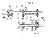
- the clamping blocks 25 are provided with bores 31 on at least two diagonally opposite corners - preferably in the area of all four corners - which pass through from the first outer side 25a to the opposite second outer side.
- the third outer side 25b and the fifth outer side 25c of the cuboid clamping block 25 are also visible in FIG. 8.
- the distance between these bores 31 is dimensioned such that, taking into account the dimensioning of square nuts 28a arranged on the screws 7 between two clamping blocks 25 (see FIG. 9), the longitudinal and transverse beams 2, 3 engage in a form-fitting manner between these nuts 28a.
- the bores 31 are thus arranged in the clamping blocks 25 in such a way that half the width of the nuts 28a and half the width of the longitudinal or transverse beams 2, 3 results in the spacing of the bore 31 from the central plane of the clamping block 25. In this way, in the area of a node (see FIG. 9), the two intersecting beams 2, 3 can be properly fixed in position with the aid of only two screws and four nuts 28a placed on the screws 7 between the two clamping blocks 25.
- the two clamping blocks 25 are clamped together via external nuts 28b.
- FIGS. 6 to 9 To fasten the lines 1 by means of the line carrier 9, further cuboidal clamping blocks 26 are also provided in the embodiment of FIGS. 6 to 9, which have two through bores. The distance between these bores is dimensioned such that - taking into account the dimensioning of the square nuts 28a arranged between two clamping blocks - the cross members 3 engage in a form-fitting manner between these nuts 28a (cf. FIGS. 6 and 7).
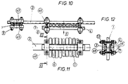
- the longitudinal beams 2 and the transverse beams 3 have a U-shaped cross-sectional profile.
- the clamping blocks 45 (cf. FIG. 13) have two continuous grooves 49a, 49b on the first outside 45a, which open out on the third outside 45b and the opposite fourth outside of the cuboid clamping blocks 45.
- the cuboidal clamping blocks 45 are provided with bores 51 which pass from the first outer side 45a to the opposite, planar second outer side.
- the bores 51 lie outside of the grooves 49a, 49b, the spacing of which is dimensioned in such a way that the two webs of the U-shaped cross-sectional profile of the longitudinal and transverse beams 2, 3 engage in a form-fitting manner in these grooves (cf. FIG. 14).
- two clamping blocks 45 are arranged so that the groove sides of these clamping blocks face each other and the grooves are perpendicular to one another.
- the longitudinal and transverse beams 2, 3 are then clamped together in the manner shown in FIG. 14, two clamping blocks 45 each being held together by two diagonally arranged screws 7 with attached nuts 9.
- the line carriers 4 also have a U-shaped cross-sectional profile.
- further clamping blocks 46 are used, which - like the clamping blocks 45 - have two continuous grooves on one outside for the positive engagement of the two webs of the U-shaped cross-sectional profile of the cross beams 3 or the cable carriers 4, which, however, are only provided with two bores arranged outside the two grooves for receiving screws 7 (cf. FIGS. 10 to 12).
Landscapes
- Engineering & Computer Science (AREA)
- Power Engineering (AREA)
- General Engineering & Computer Science (AREA)
- Mechanical Engineering (AREA)
- Insulating Bodies (AREA)
- Installation Of Indoor Wiring (AREA)
- Installation Of Bus-Bars (AREA)
- Insulating Of Coils (AREA)
Claims (12)
caractérisé par les particularités suivantes:
Priority Applications (3)
| Application Number | Priority Date | Filing Date | Title |
|---|---|---|---|
| EP84110862A EP0174385B1 (fr) | 1984-09-12 | 1984-09-12 | Dispositif de support pour conducteurs électriques |
| DE8484110862T DE3471397D1 (en) | 1984-09-12 | 1984-09-12 | Holder for electrical conductors |
| AT84110862T ATE34483T1 (de) | 1984-09-12 | 1984-09-12 | Halterung fuer elektrische leitungen. |
Applications Claiming Priority (1)
| Application Number | Priority Date | Filing Date | Title |
|---|---|---|---|
| EP84110862A EP0174385B1 (fr) | 1984-09-12 | 1984-09-12 | Dispositif de support pour conducteurs électriques |
Publications (2)
| Publication Number | Publication Date |
|---|---|
| EP0174385A1 EP0174385A1 (fr) | 1986-03-19 |
| EP0174385B1 true EP0174385B1 (fr) | 1988-05-18 |
Family
ID=8192149
Family Applications (1)
| Application Number | Title | Priority Date | Filing Date |
|---|---|---|---|
| EP84110862A Expired EP0174385B1 (fr) | 1984-09-12 | 1984-09-12 | Dispositif de support pour conducteurs électriques |
Country Status (3)
| Country | Link |
|---|---|
| EP (1) | EP0174385B1 (fr) |
| AT (1) | ATE34483T1 (fr) |
| DE (1) | DE3471397D1 (fr) |
Cited By (2)
| Publication number | Priority date | Publication date | Assignee | Title |
|---|---|---|---|---|
| CN107958766A (zh) * | 2017-11-16 | 2018-04-24 | 温州电力设计有限公司 | 低损耗变电设备 |
| CN108053983A (zh) * | 2018-01-11 | 2018-05-18 | 山东电力设备有限公司 | 一种110kV双绕组车载变压器引线结构 |
Families Citing this family (2)
| Publication number | Priority date | Publication date | Assignee | Title |
|---|---|---|---|---|
| DE4416381C2 (de) * | 1994-05-04 | 1996-09-12 | Aeg Tro Transformatoren Gmbh | Anordnung zur Führung und Befestigung von Ableitungsdrähten in elektrischen Transformatoren oder Drosselspulen |
| ES2261091B1 (es) * | 2005-06-16 | 2007-11-01 | Alfredo Javier Ibisate Gracia | Sistema de amarre entre perfiles. |
Family Cites Families (3)
| Publication number | Priority date | Publication date | Assignee | Title |
|---|---|---|---|---|
| FR987516A (fr) * | 1949-04-01 | 1951-08-14 | Alsthom Cgee | Nouvelles dispositions de montage des câbles électriques des tableaux, châssis, armoires, coffrets de répartition, etc. |
| FR1287983A (fr) * | 1961-04-21 | 1962-03-16 | Dispositif de serrage pour l'assemblage d'un support formé de tubes | |
| SE428068B (sv) * | 1981-09-24 | 1983-05-30 | Figeholms Bruk Ab | Stag for utanfor lindningar anordnade ledare i transformatorer och reaktorer |
-
1984
- 1984-09-12 DE DE8484110862T patent/DE3471397D1/de not_active Expired
- 1984-09-12 EP EP84110862A patent/EP0174385B1/fr not_active Expired
- 1984-09-12 AT AT84110862T patent/ATE34483T1/de not_active IP Right Cessation
Cited By (3)
| Publication number | Priority date | Publication date | Assignee | Title |
|---|---|---|---|---|
| CN107958766A (zh) * | 2017-11-16 | 2018-04-24 | 温州电力设计有限公司 | 低损耗变电设备 |
| CN107958766B (zh) * | 2017-11-16 | 2019-11-01 | 温州电力设计有限公司 | 低损耗变电设备 |
| CN108053983A (zh) * | 2018-01-11 | 2018-05-18 | 山东电力设备有限公司 | 一种110kV双绕组车载变压器引线结构 |
Also Published As
| Publication number | Publication date |
|---|---|
| DE3471397D1 (en) | 1988-06-23 |
| ATE34483T1 (de) | 1988-06-15 |
| EP0174385A1 (fr) | 1986-03-19 |
Similar Documents
| Publication | Publication Date | Title |
|---|---|---|
| EP1117167A1 (fr) | Dispositif pour connecter des barres omnibus aux contacts d'un appareil électrique | |
| DE2639642A1 (de) | Anschlusskontaktanordnung mit klemmkontaktstuecken | |
| EP0995205B1 (fr) | Bobine d'inductance planaire multicouche et son procede de production | |
| EP0442591B1 (fr) | Installation de commutation multichamp avec une disposition de barres omnibus | |
| EP0793243B1 (fr) | Transformateur | |
| BE1025564A1 (de) | Modularer Anschlussblock mit einer Mehrzahl von Anschlussmodulen für ein Elektronikbauteil | |
| DE69510317T2 (de) | Metallgekapselte gasisolierte Schaltvorrichtung | |
| EP0616401B1 (fr) | Pile de barres omnibus | |
| EP0174385B1 (fr) | Dispositif de support pour conducteurs électriques | |
| DE19918842B4 (de) | Sammelanschluß für elektr. Verteileranlagen | |
| DE102013103441A1 (de) | Modulare halterung fuer elektrische leiter | |
| DE3508327A1 (de) | Stromwandler mit einem rechteckigen eisenkern | |
| EP0465883B1 (fr) | Borne de connexion pour fixation sur un rail conducteur | |
| DE2850657A1 (de) | Drosselspule | |
| EP1356548A1 (fr) | Dispositif de contact pour la liaison liberable d'un bloc d'assemblage mobile avec des rails conducteurs fixes | |
| DE2454508B2 (de) | Verbindungsvorrichtung für Fernmeldekreise | |
| DE2733895C2 (de) | Einbauvorrichtung zum Einschub eines Bausteins | |
| EP0304513B1 (fr) | Dispositif d'éclairage à basse tension | |
| DE2714227C3 (de) | Hülsenartiger Isolator | |
| DE2425457A1 (de) | Schaltverbindung fuer wicklungen elektrischer maschinen, insbesondere turbogeneratoren | |
| DE3527206A1 (de) | Anschlussblock fuer stromrichtergeraete | |
| AT523609B1 (de) | Schaltschrank für eine elektrische Umrichterbaugruppe | |
| DE3213883C2 (de) | Schaltleitungsbündel für Transformatoren | |
| DE10049086A1 (de) | Reihenklemme | |
| DE9211879U1 (de) | Elektrischer Baustein |
Legal Events
| Date | Code | Title | Description |
|---|---|---|---|
| PUAI | Public reference made under article 153(3) epc to a published international application that has entered the european phase |
Free format text: ORIGINAL CODE: 0009012 |
|
| AK | Designated contracting states |
Kind code of ref document: A1 Designated state(s): AT CH DE FR GB IT LI SE |
|
| 17P | Request for examination filed |
Effective date: 19860430 |
|
| 17Q | First examination report despatched |
Effective date: 19870803 |
|
| GRAA | (expected) grant |
Free format text: ORIGINAL CODE: 0009210 |
|
| ITF | It: translation for a ep patent filed | ||
| AK | Designated contracting states |
Kind code of ref document: B1 Designated state(s): AT CH DE FR GB IT LI SE |
|
| REF | Corresponds to: |
Ref document number: 34483 Country of ref document: AT Date of ref document: 19880615 Kind code of ref document: T |
|
| GBT | Gb: translation of ep patent filed (gb section 77(6)(a)/1977) | ||
| REF | Corresponds to: |
Ref document number: 3471397 Country of ref document: DE Date of ref document: 19880623 |
|
| ET | Fr: translation filed | ||
| PLBE | No opposition filed within time limit |
Free format text: ORIGINAL CODE: 0009261 |
|
| STAA | Information on the status of an ep patent application or granted ep patent |
Free format text: STATUS: NO OPPOSITION FILED WITHIN TIME LIMIT |
|
| 26N | No opposition filed | ||
| PGFP | Annual fee paid to national office [announced via postgrant information from national office to epo] |
Ref country code: FR Payment date: 19920807 Year of fee payment: 9 |
|
| PGFP | Annual fee paid to national office [announced via postgrant information from national office to epo] |
Ref country code: AT Payment date: 19920811 Year of fee payment: 9 |
|
| PGFP | Annual fee paid to national office [announced via postgrant information from national office to epo] |
Ref country code: SE Payment date: 19920814 Year of fee payment: 9 Ref country code: GB Payment date: 19920814 Year of fee payment: 9 Ref country code: CH Payment date: 19920814 Year of fee payment: 9 |
|
| ITTA | It: last paid annual fee | ||
| PGFP | Annual fee paid to national office [announced via postgrant information from national office to epo] |
Ref country code: DE Payment date: 19921123 Year of fee payment: 9 |
|
| PG25 | Lapsed in a contracting state [announced via postgrant information from national office to epo] |
Ref country code: GB Effective date: 19930912 Ref country code: AT Effective date: 19930912 |
|
| PG25 | Lapsed in a contracting state [announced via postgrant information from national office to epo] |
Ref country code: SE Effective date: 19930913 |
|
| PG25 | Lapsed in a contracting state [announced via postgrant information from national office to epo] |
Ref country code: LI Effective date: 19930930 Ref country code: CH Effective date: 19930930 |
|
| GBPC | Gb: european patent ceased through non-payment of renewal fee |
Effective date: 19930912 |
|
| PG25 | Lapsed in a contracting state [announced via postgrant information from national office to epo] |
Ref country code: FR Free format text: LAPSE BECAUSE OF NON-PAYMENT OF DUE FEES Effective date: 19940531 |
|
| REG | Reference to a national code |
Ref country code: CH Ref legal event code: PL |
|
| PG25 | Lapsed in a contracting state [announced via postgrant information from national office to epo] |
Ref country code: DE Effective date: 19940601 |
|
| REG | Reference to a national code |
Ref country code: FR Ref legal event code: ST |
|
| EUG | Se: european patent has lapsed |
Ref document number: 84110862.4 Effective date: 19940410 |