EP0174698B1 - Generator für Fernsehspezialeffekte - Google Patents
Generator für Fernsehspezialeffekte Download PDFInfo
- Publication number
- EP0174698B1 EP0174698B1 EP85201423A EP85201423A EP0174698B1 EP 0174698 B1 EP0174698 B1 EP 0174698B1 EP 85201423 A EP85201423 A EP 85201423A EP 85201423 A EP85201423 A EP 85201423A EP 0174698 B1 EP0174698 B1 EP 0174698B1
- Authority
- EP
- European Patent Office
- Prior art keywords
- television
- reached
- picture
- count
- store
- Prior art date
- Legal status (The legal status is an assumption and is not a legal conclusion. Google has not performed a legal analysis and makes no representation as to the accuracy of the status listed.)
- Expired
Links
Images


Classifications
-
- H—ELECTRICITY
- H04—ELECTRIC COMMUNICATION TECHNIQUE
- H04N—PICTORIAL COMMUNICATION, e.g. TELEVISION
- H04N5/00—Details of television systems
- H04N5/222—Studio circuitry; Studio devices; Studio equipment
- H04N5/262—Studio circuits, e.g. for mixing, switching-over, change of character of image, other special effects ; Cameras specially adapted for the electronic generation of special effects
Definitions
- the invention relates to a television special effects generator comprising: an input for receiving a video signal in the form of successive samples encoded in digital form and correspoond- ing to picture elements on display, the display being built up from line and field sequential scans; a frame store for storing video signals forming a television frame; input addressing means for writing the input video signal samples into desired locations in the store; output addressing means for reading video signal samples from selected locations in the store; and an output coupled to the store for receiving successive video signal samples read from the store as the output video signal; in which the output addressing means is capable of generating read address signals which cause the store locations to be read in a sequence which corresponds to incrementally increasing (or decreasing) picture lines in a television field until a given point is reached and then incrementally decreasing (or increasing) picture lines: characterised in that for alternate television fields the stepping of the output addresses is inhibited for one line period when the given point is reached.
- Such special effects generators are normally capable of expanding (zooming) and compressing (squeezing) a television picture and of moving the picture to selected parts of the display screen. They may also be capable of causing multiple pictures to be displayed and of rotating a picture about an axis perpendicular to the plane of the picture and one or more axes in the plane of the picture. Such generators have also been used for displaying a reversed picture which, if a squeeze- zoom action is combined with a picture direction reversal, can produce an effect in which the picture appears to "flip" like a card being turned over. These effects are produced by appropriate control of the write and read addresses of the frame store which are normally controlled by means of counters.
- a reflection effect has been produced by mixing a picture with a reversed picture and ensuring that the centre line matches. This gives a mirror image of the left hand side of the screen in the right hand side. This effect is, however, complicated to set up and requires a two channel mixer for its achievement.
- U.K. Patent No. GB-A-1583928 discloses a television effects generator as set forth in the opening paragraph in which the output addressing means comprises up/down counters whose counting directions are reversed to produce a mirror effect. This provides a simple means for producing a mirror image of one half of the displayed picture in the other half of the displayed picture. All that is required is a simple instruction to the read address generator to reverse its sequence of addresses when a given point is reached to cause samples from the store to be read out in reverse order. Thus the need for two channels to produce this effect is eliminated.
- the invention provides a television special effects generator as set forth in the opening paragraph characterised in that for alternate television fields the incremental increasing (or decreasing) of the output addresses is inhibited for one line period when the given point is reached.
- the output addressing means may be capable of generating read address signals which cause the store locations to be read in a sequence which corresponds to incrementally increasing (or decreasing) picture element positions along a television line until a given point is reached and then incrementally decreasing (or increasing) picture element positions, characterised in thatthe stepping of the output addressing means is inhibited for one sampling period when the given point is reached.
- the video signal comprises a first data stream representing the luminance component and a second data stream comprising multiplexed components representing colour difference components Cr and Cb
- means may be provided for advancing one colour difference component by a sampling period and delaying the other colour difference component by one sampling period after the given point is reached.
- Means may be provided to vary the given point. This enables the line about which the picture is reflected to be positioned at any selected vertical or horizontal position on the picture.
- Means may be provided for expanding the television picture represented by the video signal after the given point has been reached. This enables the whole of the display screen to be filled when the reflection takes place about a line not on the picture centre line.
- the television special effects generator may be characterised in that the output addressng means comprises a first up/down counter which is clocked at the sampling rate and which is controlled to reverse its count direction when a given count has been reached and/or a second up/down counter which is clocked at the television line rate and which is controlled to reverse its count direction when a given count has been reached.
- This provides a simple way of reversing the sequence of addresses generated by the address generator.
- the or the first and/or second up/down counters may be presettable to a desired initial count state.
- the special effects generated shown in block schematic form in Figure 1 comprises a frame store 1 in the form of a random access memory, an input highway 2 for conveying an input video signal in the form of two 8 bit PCM words, one for luminance at a sampling rate of 13.5 MHz and one for two interleaved colour difference signals at a sampling rate for each colour difference signal of 6.75 MHz giving a multiplexed 13.5 MHz sampling rate, and output highway 3 for conveying an output video signal, a memory write addressor 4, a memory read addressor 5, and a read addressor control unit 6.
- the read addressor 5 comprises a clock generator 7, an up/down counter 8 and an address encoder 9.
- the write addressor 4 is similar to the read addressor 5 but may have a unidirectional counter instead of the up/down counter 8.
- the video input signal samples on the highway 2 written into selected locations in the frame store 1 under the control of the write addressor 4.
- the stored samples are then read out under the control of the read addressor 5 onto the highway 3 to form the output video signal.
- the control unit 6 produces a signal which causes the up/down counter to change count direction when a given, pre-set, count is reached. Conveniently this count corresponds to the mid point of the picture in either or both of the horizontal and vertical directions.
- the up/down counter 8 is constructed as two separate counters the first clocked at the sampling rate and the second at the television line rate.
- the control unit 6 thus includes a selection means for selecting whether or not a mirror effect is desired in the horizontal and/or vertical direction. If so it compares the counter output with a pre-set count and causes reversal of the count direction of the counter when that count has been reached.
- the up/down counters may be presettable so that a picture reversal can be effected by presetting the counters to a maximum count and causing them to count down either to zero or, if the mirror effect is required, to a given count before reversing and counting up.
- Figures 2 and 3 illustrate the effects obtainable by generating the read addresses for the frame store 1 by means of addressors including up/ down counters.
- Figures 2a) and 2d) show a picture produced normally i.e. both up/down counters are arranged to count up from zero to the maximum count.
- Figure 2b) shows the effect produced when the up/down counter clocked at the line frequency is arranged to count up from zero to a given count (in this case to a count corresponding to the centre line of the picture) and then count down to zero.
- Figure 2c) shows the effect when the up/down counter is preset to the maximum count value and is caused to count down to the given count and then to count up back to the preset maximum count.
- Figure 3 illustrates the effects produced when both up/down counters are reversed at a given count.
- both counters start from the zero count
- the line rate clocked counter starts from a preset maximum count and the sample rate clocked counter starts from zero
- the line rate clocked counter starts from zero and the sample rate clocked counter starts from a preset maximum count
- both the line rate and sample rate clocked counters start from a preset maximum count.
- Further effects may be produced by pre- or post-processing of the video signal. For example, if a rotator is connected before the frame store and the effect illustrated in Figure 3 is selected a combined effect simulating a kaleidoscope can be obtained. If a rotator is connected after the frame store a completely different effect is produced since this would result in the total picture being rotated together rather than the four quadrants being separately rotated.
- Figure 4 illustrates the problems involved with the reversal of the up/ down counter clocked at line rate.
- the crosses represent samples corresponding to a diagonal line on the picture on lines n-2, n-1, n, n+1, n+2 of a picture where n is the line about which the mirror effect is to be produced. It is assumed thatthe television picture, as is normal, is assembled from two interlaced fields 0 and 1.
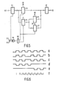
- Figure 5 shows an arrangement for correcting the positions of the Cr and Cb components.
- those lines having a diagonal slash through them represent 8 bit parallel highways, the other lines representing single signal paths.
- An input 50 is connected to an 8 bit latch 51 which is clocked at the sample rate from clock pulses applied to an input 52.
- the output of the latch 51 is fed to two further latches 53 and 54.
- the latch 53 has its output enabled by a signal applied to input 55, the signal being of the form illustrated in Figure 6a).
- the latch 54 is permanently enabled.
- the output of latch 54 is fed to a buffer 65 which is enabled by a signal at input 56 which takes the form illustrated in Figure 6d) and to a latch 57 which is enabled by a signal at input 58 which takes the form illustrated in Figure 6e).
- the input 52 is also connected to a first input of an exclusive OR- gate 59 whose output is connected to the clock input of a D-type bistable circuit 60 which provides clock signals to the latches 53, 54 and 57 at half the sample rate, the clock signal to the latch 54 being in antiphase to the clock signal to the latches 53 and 57.
- the outputs of the latches 53, 55 and 57 are fed via a buffer 61 to an output 62.
- An invert signal is applied to input 63 which causes the phase of the clock outputs from the bistable 60 to be reversed when it changes state.
- the latches 51,53,54,57 are tri-state latches and may be a type 74 LS 374 TTL integrated circuits while the buffer 55 also has a tri-state output and may be a type 74 LS 244 integrated circuit.
- the arrangement shown in Figure 5 effectively advances the Cb sample by the sample clock period and retards the Cr sample by the sample clock period when the given count is reached by causing the clock signals to be inverted by applying a signal to input 63 which via the exclusive OR gate 59 inverts the sample clock applied to the clock input of the bistable 60.
- the change in clock signals is shown in Figure 6b) and c), Figure 6b) showing the signal applied to latches 53 and 57 and Figure 6c) showing the signal applied to latch 54.
- the enable signals to the latch 57 and buffer 65 cause the Cr signal to pass via the latch 57 ratherthan the buffer 65.
- the Cr, Cb sequence is maintained.
- the luminance component after the mirror point is so timed that a one sample period error between the luminance and colour difference components is produced.
- a one sample period delay between the change in chrominance and the corresponding change in luminance which may give rise to false colours on sharp transitions.
- This may be overcome by reducing the delay in the luminance path by one sampling period when the given count is reached. This can be achieved simply by bypassing a latch which is clocked at the sampling rate.
- the picture reversal, or mirroring is produced about a horizontal or vertical centre line. If the horizontal orvertical line is not centrally placed but is placed towards the originating edge then a gap will appear at the other edge unless the mirrored portion is expanded. Similarly if the line is nearer to the mirrored edge part of the picture will be missing from the mirrored portion.
- the mirror lines need not be vertical or horizontal if the counters are preset more than once per field.
- the mirror line may be made continuously adjustable by including a potentiometer control, analogue to digital converter and an adder in the path to set the given count.
- the memory read addressor need not comprise an up/down counter, although this gives a convenient implementation.
- a unidirectional counter may be used to address a read only memory encoder which is programmed to produce an address reversal at a given count of the unidirectional counter.
- the memory write addressor 4 may be controlled completely independently of the memory read addressor 5 and consequently effects such as compression, expansion and rotation may be performed using the memory write addressor 4 and combined with the mirror effect using the memory read addressor 5.
Landscapes
- Engineering & Computer Science (AREA)
- Multimedia (AREA)
- Signal Processing (AREA)
- Studio Circuits (AREA)
- Processing Of Color Television Signals (AREA)
Claims (7)
Applications Claiming Priority (2)
| Application Number | Priority Date | Filing Date | Title |
|---|---|---|---|
| GB8423325 | 1984-09-14 | ||
| GB08423325A GB2164520A (en) | 1984-09-14 | 1984-09-14 | Television special effects generator |
Publications (2)
| Publication Number | Publication Date |
|---|---|
| EP0174698A1 EP0174698A1 (de) | 1986-03-19 |
| EP0174698B1 true EP0174698B1 (de) | 1990-02-14 |
Family
ID=10566743
Family Applications (1)
| Application Number | Title | Priority Date | Filing Date |
|---|---|---|---|
| EP85201423A Expired EP0174698B1 (de) | 1984-09-14 | 1985-09-10 | Generator für Fernsehspezialeffekte |
Country Status (5)
| Country | Link |
|---|---|
| US (1) | US4700228A (de) |
| EP (1) | EP0174698B1 (de) |
| JP (1) | JPS6173485A (de) |
| DE (1) | DE3576062D1 (de) |
| GB (1) | GB2164520A (de) |
Families Citing this family (12)
| Publication number | Priority date | Publication date | Assignee | Title |
|---|---|---|---|---|
| DE3722172A1 (de) * | 1987-07-04 | 1989-01-12 | Thomson Brandt Gmbh | Verfahren und vorrichtung zur ausschnittvergroesserung eines fernsehbildes |
| US4864386A (en) * | 1988-09-12 | 1989-09-05 | Tektronix, Inc. | Double display mode for differential gain |
| US5053762A (en) * | 1989-04-28 | 1991-10-01 | Microtime, Inc. | Page turn simulator |
| GB8918584D0 (en) * | 1989-08-15 | 1989-09-27 | British Telecomm | Image reversing unit |
| US5293540A (en) * | 1991-07-29 | 1994-03-08 | Nview Corporation | Method and apparatus for merging independently generated internal video with external video |
| BE1005197A3 (fr) * | 1991-08-23 | 1993-05-25 | Seldis | Dispositif de prise de vues et de reproduction d'au moins une image. |
| JP3223639B2 (ja) * | 1993-04-15 | 2001-10-29 | ソニー株式会社 | 画像メモリのリードアドレス発生方法 |
| JPH06303516A (ja) * | 1993-04-17 | 1994-10-28 | Sony Corp | 画像変換装置 |
| EP0655710B1 (de) | 1993-11-29 | 2000-10-04 | Olympus Optical Co., Ltd. | Anordnung zur Bildrotation und Überlagerung |
| WO1998011720A1 (fr) * | 1996-09-11 | 1998-03-19 | Sony Corporation | Dispositif d'effets speciaux, procede de traitement d'image et procede de generation d'image objective |
| KR100468675B1 (ko) * | 1997-07-25 | 2005-03-16 | 삼성전자주식회사 | 스태틱램자기테스트회로의어드레스발생기및어드레스발생방법 |
| TWI748447B (zh) * | 2020-05-12 | 2021-12-01 | 瑞昱半導體股份有限公司 | 影音介面之控制訊號傳輸電路及控制訊號接收電路 |
Family Cites Families (5)
| Publication number | Priority date | Publication date | Assignee | Title |
|---|---|---|---|---|
| US4011401A (en) * | 1975-04-25 | 1977-03-08 | Sarkes Tarzian, Inc. | Special effects generator capable of repositioning image segments |
| JPS5836780B2 (ja) * | 1975-08-15 | 1983-08-11 | 沖電気工業株式会社 | ガゾウヘンカンホウシキ |
| JPS5345120A (en) * | 1976-10-05 | 1978-04-22 | Tokyo Hoso:Kk | Video special effect device |
| DE2725362C3 (de) * | 1977-06-04 | 1980-08-28 | Robert Bosch Gmbh, 7000 Stuttgart | Verfahren zum Verarbeiten von Farbfernsehsignalen |
| NL7903241A (nl) * | 1979-04-25 | 1980-10-28 | Philips Nv | Televisie sleutelsignaalschakeling. |
-
1984
- 1984-09-14 GB GB08423325A patent/GB2164520A/en not_active Withdrawn
-
1985
- 1985-09-10 US US06/774,419 patent/US4700228A/en not_active Expired - Fee Related
- 1985-09-10 EP EP85201423A patent/EP0174698B1/de not_active Expired
- 1985-09-10 DE DE8585201423T patent/DE3576062D1/de not_active Expired - Lifetime
- 1985-09-14 JP JP60202557A patent/JPS6173485A/ja active Pending
Also Published As
| Publication number | Publication date |
|---|---|
| DE3576062D1 (de) | 1990-03-22 |
| US4700228A (en) | 1987-10-13 |
| JPS6173485A (ja) | 1986-04-15 |
| GB8423325D0 (en) | 1984-10-17 |
| EP0174698A1 (de) | 1986-03-19 |
| GB2164520A (en) | 1986-03-19 |
Similar Documents
| Publication | Publication Date | Title |
|---|---|---|
| EP0174698B1 (de) | Generator für Fernsehspezialeffekte | |
| US4774581A (en) | Television picture zoom system | |
| US4707742A (en) | Video signal processing arrangement | |
| EP0287331B1 (de) | Speichersystem für bemusterte Daten, zum Beispiel für ein Bildvergrösserungssystem in einem Fernsehempfänger | |
| US4796089A (en) | Television receiver display apparatus having multi-image display capability | |
| US4680630A (en) | Apparatus for processing digital video signals to produce a television image by line and field sequential scanning | |
| JP2880168B2 (ja) | 拡大表示可能な映像信号処理回路 | |
| HK1004048B (en) | Sampled data memory system eg for a television picture magnification system | |
| US5434624A (en) | Apparatus for producing a multi-scene video signal | |
| US4970588A (en) | Video monitoring apparatus with plural inputs | |
| KR0167799B1 (ko) | 영상신호압축장치 | |
| US4814875A (en) | Digital envelope shaping apparatus | |
| US5181110A (en) | Video signal processing circuit capable of enlarging and displaying a picture | |
| EP0392618A1 (de) | Einrichtung zur Erzeugung eines Horizontalrückstellsignals, synchron mit einem hilfsträgerverriegelten Taktsignal | |
| US4635116A (en) | Video signal delay circuit | |
| US4412250A (en) | Memory-type sync generator with reduced memory requirements | |
| US4695873A (en) | Horizontal line data position and burst phase encoding apparatus and method | |
| EP0420281B1 (de) | Wellenformanzeigeschaltung mit Luminanzinterpolation | |
| EP0056052B1 (de) | Synchronisierender kreis, anpassbar an verschiedene fernsehsysteme | |
| KR100232028B1 (ko) | 모자이크 효과 발생 장치 | |
| GB2161666A (en) | Video signal processing arrangement | |
| KR0165278B1 (ko) | 게이트 펄스 발생회로 | |
| JP2986653B2 (ja) | クロック選択回路 | |
| JPS62143555A (ja) | 光学走査器出力の垂直分解能の向上方法および同方法を用いる光学走査器 | |
| JP3648923B2 (ja) | カラー映像信号の処理装置 |
Legal Events
| Date | Code | Title | Description |
|---|---|---|---|
| PUAI | Public reference made under article 153(3) epc to a published international application that has entered the european phase |
Free format text: ORIGINAL CODE: 0009012 |
|
| AK | Designated contracting states |
Kind code of ref document: A1 Designated state(s): DE FR GB IT |
|
| 17P | Request for examination filed |
Effective date: 19860827 |
|
| RAP3 | Party data changed (applicant data changed or rights of an application transferred) |
Owner name: N.V. PHILIPS' GLOEILAMPENFABRIEKEN Owner name: PHILIPS ELECTRONIC AND ASSOCIATED INDUSTRIES LIMIT |
|
| 17Q | First examination report despatched |
Effective date: 19890404 |
|
| GRAA | (expected) grant |
Free format text: ORIGINAL CODE: 0009210 |
|
| AK | Designated contracting states |
Kind code of ref document: B1 Designated state(s): DE FR GB IT |
|
| REF | Corresponds to: |
Ref document number: 3576062 Country of ref document: DE Date of ref document: 19900322 |
|
| ITF | It: translation for a ep patent filed | ||
| ET | Fr: translation filed | ||
| PLBE | No opposition filed within time limit |
Free format text: ORIGINAL CODE: 0009261 |
|
| STAA | Information on the status of an ep patent application or granted ep patent |
Free format text: STATUS: NO OPPOSITION FILED WITHIN TIME LIMIT |
|
| 26N | No opposition filed | ||
| ITTA | It: last paid annual fee | ||
| ITPR | It: changes in ownership of a european patent |
Owner name: CAMBIO RAGIONE SOCIALE;PHILIPS ELECTRONICS N.V. |
|
| REG | Reference to a national code |
Ref country code: FR Ref legal event code: CD |
|
| PGFP | Annual fee paid to national office [announced via postgrant information from national office to epo] |
Ref country code: FR Payment date: 19950927 Year of fee payment: 11 |
|
| PGFP | Annual fee paid to national office [announced via postgrant information from national office to epo] |
Ref country code: DE Payment date: 19951123 Year of fee payment: 11 |
|
| PGFP | Annual fee paid to national office [announced via postgrant information from national office to epo] |
Ref country code: GB Payment date: 19960830 Year of fee payment: 12 |
|
| PG25 | Lapsed in a contracting state [announced via postgrant information from national office to epo] |
Ref country code: FR Effective date: 19960930 |
|
| PG25 | Lapsed in a contracting state [announced via postgrant information from national office to epo] |
Ref country code: DE Effective date: 19970603 |
|
| REG | Reference to a national code |
Ref country code: FR Ref legal event code: ST |
|
| REG | Reference to a national code |
Ref country code: FR Ref legal event code: ST |
|
| PG25 | Lapsed in a contracting state [announced via postgrant information from national office to epo] |
Ref country code: GB Free format text: LAPSE BECAUSE OF NON-PAYMENT OF DUE FEES Effective date: 19970910 |
|
| GBPC | Gb: european patent ceased through non-payment of renewal fee |
Effective date: 19970910 |