EP0175009A1 - Matrixdrucker, insbesondere Matrixzeilendrucker - Google Patents
Matrixdrucker, insbesondere Matrixzeilendrucker Download PDFInfo
- Publication number
- EP0175009A1 EP0175009A1 EP84111106A EP84111106A EP0175009A1 EP 0175009 A1 EP0175009 A1 EP 0175009A1 EP 84111106 A EP84111106 A EP 84111106A EP 84111106 A EP84111106 A EP 84111106A EP 0175009 A1 EP0175009 A1 EP 0175009A1
- Authority
- EP
- European Patent Office
- Prior art keywords
- matrix
- printer according
- carrier
- matrix printer
- conductors
- Prior art date
- Legal status (The legal status is an assumption and is not a legal conclusion. Google has not performed a legal analysis and makes no representation as to the accuracy of the status listed.)
- Granted
Links
- 239000011159 matrix material Substances 0.000 title claims abstract description 21
- 239000004020 conductor Substances 0.000 claims description 36
- 239000000853 adhesive Substances 0.000 claims description 3
- 230000001070 adhesive effect Effects 0.000 claims description 3
- 239000012876 carrier material Substances 0.000 claims description 3
- 230000007704 transition Effects 0.000 claims description 3
- 238000004519 manufacturing process Methods 0.000 description 4
- 238000003754 machining Methods 0.000 description 2
- 239000000463 material Substances 0.000 description 2
- 230000000284 resting effect Effects 0.000 description 2
- 229910000838 Al alloy Inorganic materials 0.000 description 1
- 230000002411 adverse Effects 0.000 description 1
- 238000005452 bending Methods 0.000 description 1
- 238000005266 casting Methods 0.000 description 1
- 238000010304 firing Methods 0.000 description 1
- 229910001234 light alloy Inorganic materials 0.000 description 1
- 238000012423 maintenance Methods 0.000 description 1
- 238000005476 soldering Methods 0.000 description 1
Images

Classifications
-
- B—PERFORMING OPERATIONS; TRANSPORTING
- B41—PRINTING; LINING MACHINES; TYPEWRITERS; STAMPS
- B41J—TYPEWRITERS; SELECTIVE PRINTING MECHANISMS, i.e. MECHANISMS PRINTING OTHERWISE THAN FROM A FORME; CORRECTION OF TYPOGRAPHICAL ERRORS
- B41J25/00—Actions or mechanisms not otherwise provided for
- B41J25/001—Mechanisms for bodily moving print heads or carriages parallel to the paper surface
- B41J25/006—Mechanisms for bodily moving print heads or carriages parallel to the paper surface for oscillating, e.g. page-width print heads provided with counter-balancing means or shock absorbers
-
- B—PERFORMING OPERATIONS; TRANSPORTING
- B41—PRINTING; LINING MACHINES; TYPEWRITERS; STAMPS
- B41J—TYPEWRITERS; SELECTIVE PRINTING MECHANISMS, i.e. MECHANISMS PRINTING OTHERWISE THAN FROM A FORME; CORRECTION OF TYPOGRAPHICAL ERRORS
- B41J29/00—Details of, or accessories for, typewriters or selective printing mechanisms not otherwise provided for
Definitions
- the invention relates to a matrix printer, in particular a matrix line printer, with a carrier for the printing elements which can be made to move back and forth, the drive means for the printing elements having electromagnets with cable connections, which consist of flexible strips and are connected via a switching logic to a character generator.
- Matrix printers of this type are used as data printers in data processing units with high data output or are used in word processing systems as typing printers for texts of correspondence quality.
- Such a printer is known from DE-AS 22 24 116 or US Pat. No. 3,999,644.
- a carriage, carriage or the like. equipped with a large number of electromagnets which move a pressure needle in the direction of the pressure roller and have the required cable connections at their rear ends.
- 33 electromagnets 66 cable connections are required.
- a disadvantage of such cable connections is the movement of the carrier with the electromagnet, so that the cable connections have to be moved as well.
- the fastening of the electromagnets on the carrier requires special devices in order to ensure equal distances between the printing needles and a precise vertical alignment with the printing roller or with the recording medium resting on the printing roller.
- the known solution considers a special holder necessary, which is described in DE-PS 24 24 629. Thereafter, a number of mounts are provided on the bar-shaped support in the longitudinal direction, on each of which a unit-forming electromagnet with its recording pen and its guide is arranged, and each mount has a partially cylindrical seat for receiving the electromagnet and an adjoining back, in which a bearing for guiding the recording pen is arranged.
- This design does the beam-shaped support heavy and complex and not only makes it more expensive to manufacture, but also has a significant impact on other components of the printer. The result of this is, for example, an electric drive motor which is more powerful in its performance data and more complex guide means for the beam-shaped carrier.
- the invention has for its object to propose a low-mass carrier for the electromagnets, which is easy and economical to manufacture and which meets all concerns of the pendulum movements of the print head of a matrix printer.
- the reciprocating support for the printing elements consists of an approximately angular profile bar and that the electromagnets are fastened in the upright profile bar wall opposite the recording medium or the platen, the fastening means from the side of the record carrier or the platen roller are embedded in the profile bar wall and are accessible.
- the angular profile bar combines the known beam-shaped support and the known holder for the electromagnets in a single functional part and therefore saves considerable moving mass.
- the angular profile bar can also be selected from commercially available materials and only requires fine machining.
- the position of the electromagnets can be determined with a high degree of accuracy within narrow tolerance limits by uniform machining of the longitudinal edges and the holes for the electromagnets according to distance and direction.
- the carrier according to the invention is therefore easy, precise and economical to manufacture.
- the guidance of the carrier for the oscillating movements can now also be made simple, safe and permanent by providing guide projections on the carrier parallel to the row of the pressure elements in the rest position or in the pressure position, which protrusions rest on rollers mounted on the printer chassis in a stationary manner.
- the accuracy of the guidance is improved during assembly and any maintenance work that may become necessary on the printer in that the rollers mounted on the printer chassis are individually adjustable.
- the pendulum movements are transferred to the connecting cables for the electromagnets that are moved. These pendulum movements can be absorbed without endangering the connecting cables in such a way that each of the electromagnets at the cable connections for the electromagnetic coil are connected to flat conductors insulated in a carrier material, which are guided in an arc from the moving carrier to a fixed plug contact.
- the arcs of the individual conductors unpredictably allow movement across the flat conductor cross section due to the arc in continuous operation.
- the desired arch shape is easily derived from the low bending resistance of the conductors with a flat cross-section.
- the like. can be simplified in that the flat, insulated conductors have a small thickness and are individually guided to a common holder and that in the course behind a further holder the flat, insulated conductors are brought together to form a ribbon cable and in the further course individual groups of conductors are formed, which have a plug .
- the cable connections in the immediate area of the electromagnets can also be laid economically by fastening the individual flat, insulated conductors in the immediate vicinity of the electromagnetic coil by means of a holding strip.
- a holding strip acts here as a strain relief compared to the soldering points of the connections for the electromagnetic coil.
- the fastening of the holding strip itself takes place in that the holding strip consists of an adhesive strip.
- Handling, laying, contact with printer parts and the like. can also be taken into account in that the ribbon cable is provided on both sides with the flexible holders at the transitions of the arc from one conductor direction to another conductor direction.
- ribbon cable for the print head (carrier with electromagnets and pressure elements) of the printer can also be applied in such a way that for additional electrical devices, such as e.g. Sensors, further flat conductors are provided on the ribbon cable.
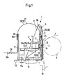
- the matrix printer shown in FIGS. 1 to 3 is designed as a matrix line printer.
- the pendulum drive itself is only indicated in Fig. 1.
- the pendulum travel la of the carrier 1 is e.g. approx. 6.5 mm on both sides, so that at least one full-width character in matrix notation is covered.
- the electromagnets 4 are constructed in the manner of a moving core magnet, so that the pressure elements 2 are always held in a rearward position or are fired into a front printing position after actuation of the electromagnet 4.
- pressure hammers with pressure peaks can also be used as pressure elements 2, such pressure hammers being able to be designed as resilient strips according to the principle of stored energy by means of a permanent magnet and for firing the pressure hammer by means of an electromagnet canceling the magnetic field of the permanent magnet.
- the electromagnets 4 are connected with the cable connections 3 to a switching logic (control) (not shown) and to a character generator.
- the matrix printer is equipped with appropriate interfaces for connection to the desired data processing system.
- the oscillating carrier 1 is made of a light material, such as an aluminum alloy, and forms a profile bar 5 in its basic shape.
- the carrier 1 can of course also be made as a casting from a light alloy or plastic.
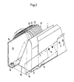
- the carrier 1 lies opposite the platen roller 6 (as a printing abutment) or the recording medium 7 resting on the platen roller 6 and moving stepwise or continuously, or the ink ribbon 7a (Figs. 1 and 2).
- the profile bar 5 forms a rear interior space 8 which is open at the top and rear and is delimited by side walls 8a and 8b.
- An approximately upright profile bar wall 9 (FIG. 3) is provided for the electromagnets 4 and a horizontal plate 10 is provided for the horizontal guide base.
- the profile bar wall 9 has a rib 11 running in the longitudinal direction in order to arrange the bores 12 for the spacing and alignment of the electromagnets 4 or their pressure needles.
- the electromagnets 4 have a guide shaft 13 which is threaded.
- the profile bar wall 9 is inclined slightly upward to allow a clear view of the writing gap.
- the guide projections 15a, 15b, 15c consist of hardened profile pieces 15d in order to ensure guidance that is as free of play and wear-free as possible in smooth or profiled rollers 17.
- the rollers 17 can be readjusted individually during assembly or after unavoidable wear.
- a bearing with an eccentricity 17a serves this purpose.
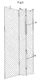
- each electromagnet 4 has flat, very thin conductors 18 and 19 in cross section, which are first soldered to the contacts of the respective electromagnetic coil and up to the top of the horizontal plate 10 or to the profile bar wall 9 and are fastened there by means of a holding strip 20 (FIG. 3). From this fastening, the conductors 18 and 19 arranged in parallel next to one another each run in an arc 21 to a contact sleeve 18a of the electronic circuit.
- the flat conductors 18 and 19 encased in a transparent, insulating carrier material each have a minimum thickness 22. They are guided in pairs 23 to a holder 24 (FIGS. 1 and 4), then run again individually or in groups to a further holder 25 on a cable holder 16a and then form a single ribbon cable 26 which has individual groups 27 of conductors , each ending in a connector 28. These plugs 28 are inserted into the associated contact sleeves 18a of the fixed electronic circuit.
- the conductor guide described is able (Fig. 2) to the left and right the described pendulum movements of e.g. 6.5 mm without causing damage in continuous operation.
- the individual flat, insulated conductors 18, 19 are fastened above (or below) the electromagnetic coils 4 by means of the holding strip 20, which consists of a simple insulating adhesive strip 30.
- the ribbon cable 26 is provided on both sides (FIG. 5) with the brackets 24 at the transitions 29 of the arc 21 from one conductor direction to another conductor direction.
- 4 and 5 is particularly suitable for additional electrical devices 31, such as for sensors and the like add more flat conductors 32, 33, 34.
- ground connection 35 is guided to the printer chassis 16 and the conductors 32 are laid to a special connector 36.
- a conductor guide is a single piece, the conductors of which are insulated on all sides. Only the conductor ends on the conductors 18 and 19 and the contact pins 37 are exposed.
Landscapes
- Accessory Devices And Overall Control Thereof (AREA)
- Impact Printers (AREA)
- Character Spaces And Line Spaces In Printers (AREA)
Abstract
Description
- Die Erfindung betrifft einen Matrixdrucker, insbesondere einen Matrixzeilendrucker, mit einem in hin- und hergehende Bewegungen versetzbaren Träger für die Druckelemente, wobei die Antriebsmittel für die Druckelemente Elektromagnete mit Kabelanschlüssen aufweisen, die aus flexiblen Streifen bestehen und über eine Schaltlogik mit einem Zeichengenerator verbunden sind.
- Derartige Matrixdrucker werden als Datendrucker in Datenverarbeitungseinheiten mit hohem Datenausstoß verwendet oder dienen in Textverarbeitungsanlagen als Schönschreibdrucker für Texte in Korrespondenzqualität.
- Ein solcher Drucker ist aus der DE-AS 22 24 116 bzw. US-PS 3,999,644 bekannt. Bei dem Drucker wird ein Schlitten, Wagen o.dgl. mit einer hohen Anzahl von Elektromagneten bestückt, die in Richtung zur Druckwalze eine Drucknadel bewegen und an ihren rückwärtigen Enden die erforderlichen Kabelanschlüsse aufweisen. Bei z.B. 33 Elektromagneten sind somit 66 Kabelanschlüsse erforderlich. Nachteilig bei solchen Kabelanschlüssen ist die Bewegung des Trägers mit dem Elektromagneten, so daß die Kabelanschlüsse mitbewegt werden müssen. Davon abgesehen, erfordert die Befestigung der Elektromagnete auf dem Träger besondere Vorrichtungen, um gleiche Abstände der Drucknadeln und eine genaue senkrechte Ausrichtung zur Druckwalze bzw. zu dem auf der Druckwalze aufliegenden Aufzeichnungsträger zu sichern. Die bekannte Lösung hält eine besondere Halterung für erforderlich, die in der DE-PS 24 24 629 beschrieben ist. Danach sind auf dem balkenförmigen Träger eine Anzahl in seiner Längsrichtung nebeneinander angebrachter Halterungen vorgesehen, auf denen jeweils ein eine Einheit bildender Elektromagnet mit seinem Aufzeichnungsstift und dessen Führung angeordnet ist und jede Halterung besitzt einen teilzylindrischen Sitz zur Aufnahme des Elektromagneten und einen sich daran anschließenden Rücken, in dem ein Lager für die Führung des Aufzeichnungsstiftes angeordnet ist. Diese Gestaltung macht den balkenförmigen Träger schwer und aufwendig und verteuert nicht nur seine Herstellung, sondern zeigt erhebliche Auswirkungen auf andere Baugruppen des Druckers. Die Folge davon ist z.B. ein stärker in seinen Leistungsdaten bemessener elektrischer Antriebsmotor und aufwendigere Führungsmittel für den balkenförmigen Träger. Es ist daher bereits aus physikalischen Gründen abzulehnen, die Masse des balkenförmigen Trägers, der um die Masse der Elektromagnete vergrößert sein muß, nun auch noch durch die Masse einer besonderen Halterung zu vergrößern. Nachteilig ist außerdem, daß die Kabelanschlüsse die bewegte träge Masse weiter vergrößern und hierbei die Lebensdauer der elektrischen Leiter nachteilig beeinflussen.
- Der Erfindung liegt die Aufgabe zugrunde, einen massearmen Träger für die Elektromagnete vorzuschlagen, der leicht und wirtschaftlich herstellbar ist und der allen Belangen der Pendelbewegungen des Druckkopfes eines Matrixdruckers gerecht wird.
- Die gestellte Aufgabe wird erfindungsgemäß dadurch gelöst, daß der hin- und hergehende Träger für die Druckelemente aus einem etwa winkelförmigen Profilstab besteht und daß die Elektromagnete in der dem Aufzeichnungsträger bzw. der Schreibwalze gegenüberliegenden, etwa aufrechtstehenden Profilstabwandung befestigt sind, wobei die Befestigungsmittel von der Seite des Aufzeichnungsträgers bzw. der Schreibwalze her in der Profilstabwandung eingelassen und zugänglich sind. Der winkelförmige Profilstab vereinigt den bekannten balkenförmigen Träger und den bekannten Halter für die Elektromagnete in einem einzigen Funktionsteil und erspart daher erheblich an bewegter Masse. Der winkelförmige Profilstab kann außerdem von handelsüblichen Materialien ausgewählt werden und bedarf lediglich einer Fein-Bearbeitung. Die Lage der Elektromagnete kann durch eine einheitliche Bearbeitung der Längskanten und der Bohrungen für die Elektromagnete nach Abstand und Richtung mit hoher Genauigkeit in engen Toleranzgrenzen festgelegt werden. Der erfindungsgemäße Träger ist daher leicht, genau und wirtschaftlich herstellbar.
- Die Führung des Trägers für die Pendelbewegungen kann nunmehr ebenfalls einfach, sicher und dauerhaft gestaltet werden, indem parallel zur Reihe der in Ruhestellung bzw. in Druckstellung befindlichen Druckelemente Führungsvorsprünge am Träger vorgesehen sind, die an auf dem Druckerchassis ortsfest gelagerten Rollen anliegen.
- Die Genauigkeit der Führung wird bei Montage und etwa notwendig werdender Wartungsarbeiten am Drucker dadurch verbessert, daß die auf dem Druckerchassis ortsfest gelagerten Rollen einzeln einstellbar sind.
- Die Pendelbewegungen übertragen sich auf die Anschlußkabel für die mitbewegten Elektromagnete. Diese Pendelbewegungen lassen sich, ohne die Anschlußkabel zu gefährden, derart auffangen, daß jeder der Elektromagnete an den Kabelanschlüssen für die Elektromagnetspule mit flachen, in einem Trägermaterial isolierten Leitern verbunden sind, die in einem Bogen vom bewegten Träger zu einem feststehenden Steckkontakt geführt sind. Die Bögen der einzelnen Leiter lassen unvorhersehbarerweise eine Bewegung quer zum flachliegenden Leiterquerschnitt aufgrund des Bogens im Dauerbetrieb zu. Die gewünschte Bogenform ergibt sich hierbei leicht aus dem geringen Biegewiderstand der mit Flachquerschnitt versehenen Leiter.
- Eine angestrebte verbesserte Leiterführung, die Übersichtlichtkeit des Leitersystems, ferner die Haltbarkeit im Dauerbetrieb, Abknickstellen, Austausch u. dgl. lassen sich dadurch vereinfachen, daß die flachen, isolierten Leiter eine geringe Dicke aufweisen und einzeln zu einer gemeinsamen Halterung geführt sind und daß im Verlauf hinter einer weiteren Halterung die flachen, isolierten Leiter zu einem Flachbandkabel zusammengeführt und im weiteren Verlauf einzelne Gruppen von Leitern gebildet sind, die einen Stecker aufweisen......
- Die Kabelanschlüsse im unmittelbaren Bereich der Elektromagnete können außerdem wirtschaftlich verlegt werden, indem die einzelnen flachen, isolierten Leiter in der unmittelbaren Nähe der Elektromagnetspule mittels eines Haltestreifens befestigt sind. Ein solcher Haltestreifen wirkt hier wie eine Zugentlastung gegenüber den Lötstellen der Anschlüsse für die Elektromagnetspule.
- Die Befestigung des Haltestreifens selbst erfolgt nach einem weiteren Merkmal dadurch, daß der Haltestreifen aus einem Klebestreifen besteht.
- Handhabung, Verlegung, Berührung mit Druckerteilen u.dgl. lassen sich ferner dahingehend berücksichtigen, indem das Flachbandkabel an den Übergängen des Bogens von einer Leiterrichtung in eine andere Leiterrichtung beidseitig mit den flexiblen Halterungen versehen ist.
- Der Grundgedanke des Flachbandkabels für den Druckkopf (Träger mit Elektromagneten und Druckelementen) des Druckers kann auch derart angewendet werden, daß für zusätzliche elektrische Einrichtungen, wie z.B. Sensoren, weitere flache Leiter an dem Flachbandkabel vorgesehen sind.
- In der Zeichnung ist ein Ausführungsbeispiel der Erfindung schematisch dargestellt und wird im folgenden näher erläutert. Es zeigen:
- Fig. 1 einen Querschnitt des Trägers für die Druckelemente,
- Fig. 2 eine Ansicht des Trägers für die Druckelemente mit Blickrichtung auf die Außenseite des winkelförmigen Profilstabs
- Fig. 3 einen stark vergrößerten Querschnitt durch den Montagestreifen,
- Fig. 4 eine Draufsicht auf das Flachbandkabel und
- Fig. 5 eine Seitenansicht oder einen Schnitt V - V zu dem Flachbandkabel gemäß Fig. 4.
- Der in den Fig. 1 bis 3 dargestellte Matrixdrucker ist als Matrixzeilendrucker gestaltet. Von dem Matrixzeilendrucker ist der Einfachheit halber nur der Träger 1 mit den Druckelementen 2, d.h. mit besonders kurzen Drucknadeln, und den Kabelanschlüssen 3 für die Elektromagnete 4 gezeichnet. Der Pendelantrieb selbst ist in Fig. 1 nur angedeutet. Der Pendelweg la des Trägers 1 beträgt z.B. nach beiden Seiten ca. 6,5 mm, so daß zumindest ein Schriftzeichen in Matrixschreibweise in voller Breite überstrichen wird.
- Die Elektromagnete 4 sind in der Bauweise eines Tauchspulenkernmagnets ausgeführt, so daß die Druckelemente 2 stets in einer rückwärtigen Position gehalten werden oder nach Betätigung des Elektromagneten 4 in eine vordere Druckposition abgeschossen werden. Anstelle der Drucknadeln können als Druckelemente 2 auch Druckhämmer mit Druckspitzen eingesetzt werden, wobei solche Druckhämmer als federnde Streifen nach dem Prinzip der gespeicherten Energie mittels eines Dauermagneten und für den Abschuß des Druckhammers mittels eines das Magnetfeld des Dauermagneten aufhebenden Elektromagneten ausgeführt sein können.
- Die Elektromagnete 4 sind mit den Kabelanschlüssen 3 an eine weiter nicht dargestellte Schaltlogik (Ansteuerung) und an einen Zeichengenerator angeschlossen. Der Matrixdrucker ist hierfür mit entsprechenden Schnittstellen zum Anschluß an die jeweils gewünschte Datenverarbeitungsanlage ausgestattet.
- Der pendelnd bewegte Träger 1 ist aus einem Leichtwerkstoff, wie z.B. aus einer Aluminiumlegierung hergestellt, und bildet in seiner Grundform einen Profilstab 5. Der Träger 1 kann selbstverständlich auch als Gußstück aus einer leichten Legierung oder aus Kunststoff hergestellt sein. Der Träger 1 liegt im montierten Zustand der Schreibwalze 6 (als Druckwiderlager) bzw. dem auf der Schreibwalze 6 aufliegenden und schrittweise oder kontinuierlich bewegten Aufzeichnungsträger 7 bzw. dem Farbband 7a gegenüber (Fig. 1 und 2). Der Schreibwalze 6 abgewandt bildet der Profilstab 5 einen hinteren, nach oben und hinten offenen Innenraum 8, der durch Seitenwände 8a und 8b begrenzt ist. Für die Elektromagnete 4 ist eine etwa aufrechtstehende Profilstabwandung 9 (Fig. 3) und für die horizontale Führungsbasis eine horizontale Platte 10 vorgesehen. Die Profilstabwandung 9 weist eine in Längsrichtung verlaufende Rippe 11 auf, um die Bohrungen 12 für die Beabstandung und Ausrichtung der Elektromagnete 4 bzw. deren Drucknadeln anzuordnen. Die Elektromagnete 4 besitzen einen Führungsschaft 13, der mit Gewinde versehen ist. In die Rippe 11 ist ein Befestigungsmittel 14, das hier aus einem Gewindering besteht, von der Seite des Aufzeichnungsträgers 7 bzw. von der Schreibwalze 6 her eingelassen und von dort auch zugänglich.
- Die Profilstabwandung 9 verläuft nach oben leicht geneigt, um einen freien Einblick in den Schreibspalt zu ermöglichen. Am Träger 1 befinden sich mehrere, dem Pendelweg la des Trägers 1 angemessene Führungsvorsprünge 15a, 15b und 15c, die an ortsfesten, drehbar am Druckerchassis 16 gelagerten Rollen 17 anliegen. Die Führungsvorsprünge 15a, 15b, 15c bestehen aus gehärteten Profilstücken 15d, um in glatten oder profilierten Rollen 17 eine möglichst spielfreie und verschleißarme Führung zu gewährleisten. Die Rollen 17 können bei Montage oder nach einem unvermeidlichen Verschleiß einzeln nachgestellt werden. Hierzu dient eine Lagerung mit einer Exzentrizität 17a.
- Die Elektromagnete 4 weisen Kabelanschlüsse 3 im Innenraum 8 auf, so daß von z.B. 33 Elektromagneten 66 Kabelanschlüsse alleine für die Elektromagnete auf dem Träger 1 aus dem Innenraum 8 heraus zu den ortsfesten Kontakten der Elektronikschaltung geführt werden müssen. Zu diesem Zweck (Fig. 1 bis 4) weist jeder Elektromagnet 4 im Querschnitt flache, sehr dünne Leiter 18 und 19 auf, die zunächst an den Kontakten der jeweiligen Elektromagnetspule verlötet sind und bis zur Oberseite der horizontalen Platte 10 bzw. zur Profilstabwandung 9 verlaufen und dort mittels eines Haltestreifens 20 befestigt sind (Fig. 3). Von dieser Befestigung verlaufen die parallel nebeneinander angeordneten Leiter 18 und 19 jeweils in einem Bogen 21 zu einer Kontaktmuffe 18a der Elektronikschaltung.
- Wie Fig. 5 zeigt, weisen die flachen, in einem transparenten, isolierenden Trägermaterial eingehüllten Leiter 18 und 19 jeweils eine minimale Dicke 22 auf. Sie sind zu Paaren 23 bis zu einer Halterung 24 geführt (Fig. 1 und 4), verlaufen danach wieder einzeln oder in Gruppen zu einer weiteren Halterung 25 an einer Kabelhalterung 16a und bilden anschließend ein einziges Flachbandkabel 26, das einzelne Gruppen 27 von Leitern aufweist, die jeweils in einem Stecker 28 enden. Diese Stecker 28 sind in die zugehörigen Kontaktmuffen 18a der ortsfesten Elektronikschaltung eingeführt. Die beschriebene Leiterführung ist in der Lage (Fig. 2), nach links und rechts die beschriebenen Pendelbewegungen von z.B. 6,5 mm auszuführen, ohne daß im Dauerbetrieb Schäden auftreten.
- Die einzelnen flachen, isolierten Leiter 18, 19 sind oberhalb (oder unterhalb) der Elektromagnetspulen 4 mittels des Haltestreifens 20 befestigt, der aus einem einfachen isolierenden Klebestreifen 30 besteht. Das Flachbandkabel 26 ist an den Übergängen 29 des Bogens 21 von einer Leiterrichtung in eine andere Leiterrichtung beidseitig (Fig. 5) mit den Halterungen 24 versehen.
- Die Leiterführung nach den Fig. 4 und 5 ist besonders geeignet, für zusätzliche elektrische Einrichtungen 31, wie z.B. für Sensoren u.dgl. weitere flache Leiter 32, 33, 34 hinzuzufügen.
- So ist der Masseanschluß 35 an das Druckerchassis 16 geführt und die Leiter 32 sind zu einem besonderen Stecker 36 verlegt. In der Herstellung ist eine solche Leiterführung ein einziges Stück, dessen Leiter allseitig isoliert sind. Lediglich die Leiterenden an den Leitern 18 und 19 sowie die Kontakstifte 37 liegen frei.
Claims (9)
Priority Applications (5)
| Application Number | Priority Date | Filing Date | Title |
|---|---|---|---|
| AT84111106T ATE36137T1 (de) | 1984-09-18 | 1984-09-18 | Matrixdrucker, insbesondere matrixzeilendrucker. |
| EP84111106A EP0175009B1 (de) | 1984-09-18 | 1984-09-18 | Matrixdrucker, insbesondere Matrixzeilendrucker |
| DE8484111106T DE3473132D1 (en) | 1984-09-18 | 1984-09-18 | Matrix printer, in particular a matrix line printer |
| US06/777,538 US4727805A (en) | 1984-09-18 | 1985-09-18 | Shuttle for matrix printers |
| JP60204582A JPS6174853A (ja) | 1984-09-18 | 1985-09-18 | マトリツクスプリンタ |
Applications Claiming Priority (1)
| Application Number | Priority Date | Filing Date | Title |
|---|---|---|---|
| EP84111106A EP0175009B1 (de) | 1984-09-18 | 1984-09-18 | Matrixdrucker, insbesondere Matrixzeilendrucker |
Publications (2)
| Publication Number | Publication Date |
|---|---|
| EP0175009A1 true EP0175009A1 (de) | 1986-03-26 |
| EP0175009B1 EP0175009B1 (de) | 1988-08-03 |
Family
ID=8192158
Family Applications (1)
| Application Number | Title | Priority Date | Filing Date |
|---|---|---|---|
| EP84111106A Expired EP0175009B1 (de) | 1984-09-18 | 1984-09-18 | Matrixdrucker, insbesondere Matrixzeilendrucker |
Country Status (5)
| Country | Link |
|---|---|
| US (1) | US4727805A (de) |
| EP (1) | EP0175009B1 (de) |
| JP (1) | JPS6174853A (de) |
| AT (1) | ATE36137T1 (de) |
| DE (1) | DE3473132D1 (de) |
Cited By (1)
| Publication number | Priority date | Publication date | Assignee | Title |
|---|---|---|---|---|
| US4686899A (en) * | 1985-09-28 | 1987-08-18 | Mannesmann Tally Gmbh | Shuttle mounting in matrix line printer |
Families Citing this family (7)
| Publication number | Priority date | Publication date | Assignee | Title |
|---|---|---|---|---|
| DE68911564T2 (de) * | 1988-03-21 | 1994-06-09 | Hewlett Packard Co | Vorrichtung zum Sichern des Flachliegens eines Blattes und der Druckspalteinstellung. |
| US5065169A (en) * | 1988-03-21 | 1991-11-12 | Hewlett-Packard Company | Device to assure paper flatness and pen-to-paper spacing during printing |
| DE8814238U1 (de) * | 1988-11-14 | 1990-03-22 | Siemens Nixdorf Informationssysteme AG, 33106 Paderborn | Druckvorrichtung |
| JPH02137967A (ja) * | 1988-11-18 | 1990-05-28 | Seikosha Co Ltd | シリアルプリンタ |
| JPH02182641A (ja) * | 1988-12-30 | 1990-07-17 | Canon Inc | 画像記録装置 |
| EP0376309B1 (de) * | 1988-12-30 | 1995-08-16 | Canon Kabushiki Kaisha | Tintenstrahlaufzeichnungsvorrichtung |
| JP2001343803A (ja) * | 2000-06-01 | 2001-12-14 | Canon Inc | 画像形成装置 |
Citations (3)
| Publication number | Priority date | Publication date | Assignee | Title |
|---|---|---|---|---|
| FR1360788A (fr) * | 1963-04-02 | 1964-05-15 | Dispositif pour l'alimentation en courant électrique d'engins mobiles | |
| US3802544A (en) * | 1972-04-28 | 1974-04-09 | Centronics Data Computer | High speed dot matrix printer |
| DE2443241A1 (de) * | 1974-09-10 | 1976-03-25 | Philips Patentverwaltung | Flachbandkabel zur fuehrung an buchungsmaschinen |
Family Cites Families (6)
| Publication number | Priority date | Publication date | Assignee | Title |
|---|---|---|---|---|
| US4359289A (en) * | 1979-11-20 | 1982-11-16 | Printronix, Inc. | Counterbalanced bidirectional shuttle drive having linear motor |
| US4425047A (en) * | 1980-09-11 | 1984-01-10 | Tokyo Electric Co., Ltd. | Printing machine capable of printing characters on long and short paper sheets |
| JPS6222376Y2 (de) * | 1980-09-25 | 1987-06-06 | ||
| US4416560A (en) * | 1981-10-16 | 1983-11-22 | Printek, Inc. | Computer printer carriage control apparatus including an encoding disk |
| US4402620A (en) * | 1981-12-23 | 1983-09-06 | International Business Machines Corp. | Compact shuttle printer mechanism |
| JPS59138473A (ja) * | 1983-01-28 | 1984-08-08 | Citizen Watch Co Ltd | インパクト型ドツト印字ヘツド |
-
1984
- 1984-09-18 DE DE8484111106T patent/DE3473132D1/de not_active Expired
- 1984-09-18 AT AT84111106T patent/ATE36137T1/de not_active IP Right Cessation
- 1984-09-18 EP EP84111106A patent/EP0175009B1/de not_active Expired
-
1985
- 1985-09-18 US US06/777,538 patent/US4727805A/en not_active Expired - Fee Related
- 1985-09-18 JP JP60204582A patent/JPS6174853A/ja active Pending
Patent Citations (3)
| Publication number | Priority date | Publication date | Assignee | Title |
|---|---|---|---|---|
| FR1360788A (fr) * | 1963-04-02 | 1964-05-15 | Dispositif pour l'alimentation en courant électrique d'engins mobiles | |
| US3802544A (en) * | 1972-04-28 | 1974-04-09 | Centronics Data Computer | High speed dot matrix printer |
| DE2443241A1 (de) * | 1974-09-10 | 1976-03-25 | Philips Patentverwaltung | Flachbandkabel zur fuehrung an buchungsmaschinen |
Cited By (1)
| Publication number | Priority date | Publication date | Assignee | Title |
|---|---|---|---|---|
| US4686899A (en) * | 1985-09-28 | 1987-08-18 | Mannesmann Tally Gmbh | Shuttle mounting in matrix line printer |
Also Published As
| Publication number | Publication date |
|---|---|
| DE3473132D1 (en) | 1988-09-08 |
| US4727805A (en) | 1988-03-01 |
| ATE36137T1 (de) | 1988-08-15 |
| EP0175009B1 (de) | 1988-08-03 |
| JPS6174853A (ja) | 1986-04-17 |
Similar Documents
| Publication | Publication Date | Title |
|---|---|---|
| EP0175009B1 (de) | Matrixdrucker, insbesondere Matrixzeilendrucker | |
| DE2652339A1 (de) | Elektrodynamische betaetigungsvorrichtung | |
| DE3018516A1 (de) | Druckkopf | |
| DE1245627B (de) | Druckhammereinrichtung | |
| DE2306309C2 (de) | Elektromagnetische Antriebseinrichtung für einen Schnelldrucker | |
| DE2216967C3 (de) | Schreibkopf für zusammengesetzte Schrift- oder Kodezeichen | |
| EP0423910B1 (de) | Drucker, insbesondere Matrixnadeldrucker | |
| DE69122846T2 (de) | Verbinder für die Kupplung eines Druckkopfes mit einer Schaltung in einem Drucker | |
| DE2309763C3 (de) | Ablenkelektrodenanordnung und Verfahren zu ihrer Herstellung | |
| DE2249125B1 (de) | Drucker mit einer auswaehlanordnung fuer druckelemente | |
| DE7030354U (de) | Druckhammerelement fuer datenverarbeitungs-druckwerke. | |
| DE3402621C2 (de) | ||
| EP0188669B1 (de) | Matrixdruckkopf | |
| EP0040883A2 (de) | Matrixdrucker mit magnetischer Druckkopfeinstellung | |
| DE2852352C2 (de) | Elektrostatischer Druckkopf | |
| EP0338176A1 (de) | Matrixnadeldruckkopf | |
| DE2924672A1 (de) | Nadeldruckwerk | |
| EP0077900B1 (de) | Vorrichtung zum Aufzeichnen von Informationen auf einen Aufzeichnungsträger | |
| DE1074124B (de) | Kon taktfedersatz insbesondere fur Einrich tungen der Nachrichten vermittlungstechnik | |
| DE2224716C3 (de) | Mosaikdrucker | |
| DE2445619B2 (de) | Elektrische druckvorrichtung | |
| DE2850780C2 (de) | Maschine zum Schreiben von Brailleschrift | |
| EP0188672B1 (de) | Matrixdruckkopf | |
| DE69111288T2 (de) | Matrixdruckkopf. | |
| DE68911278T2 (de) | Punktmatrixdrucker mit Anschlagdruckkopf. |
Legal Events
| Date | Code | Title | Description |
|---|---|---|---|
| PUAI | Public reference made under article 153(3) epc to a published international application that has entered the european phase |
Free format text: ORIGINAL CODE: 0009012 |
|
| 17P | Request for examination filed |
Effective date: 19850816 |
|
| AK | Designated contracting states |
Kind code of ref document: A1 Designated state(s): AT BE DE FR GB IT NL SE |
|
| 17Q | First examination report despatched |
Effective date: 19870409 |
|
| GRAA | (expected) grant |
Free format text: ORIGINAL CODE: 0009210 |
|
| AK | Designated contracting states |
Kind code of ref document: B1 Designated state(s): AT BE DE FR GB IT NL SE |
|
| REF | Corresponds to: |
Ref document number: 36137 Country of ref document: AT Date of ref document: 19880815 Kind code of ref document: T |
|
| REF | Corresponds to: |
Ref document number: 3473132 Country of ref document: DE Date of ref document: 19880908 |
|
| GBT | Gb: translation of ep patent filed (gb section 77(6)(a)/1977) | ||
| ITF | It: translation for a ep patent filed | ||
| ET | Fr: translation filed | ||
| PGFP | Annual fee paid to national office [announced via postgrant information from national office to epo] |
Ref country code: DE Payment date: 19890222 Year of fee payment: 5 |
|
| PLBE | No opposition filed within time limit |
Free format text: ORIGINAL CODE: 0009261 |
|
| STAA | Information on the status of an ep patent application or granted ep patent |
Free format text: STATUS: NO OPPOSITION FILED WITHIN TIME LIMIT |
|
| 26N | No opposition filed | ||
| PG25 | Lapsed in a contracting state [announced via postgrant information from national office to epo] |
Ref country code: GB Effective date: 19890918 Ref country code: AT Effective date: 19890918 |
|
| PG25 | Lapsed in a contracting state [announced via postgrant information from national office to epo] |
Ref country code: SE Effective date: 19890919 |
|
| PG25 | Lapsed in a contracting state [announced via postgrant information from national office to epo] |
Ref country code: BE Effective date: 19890930 |
|
| BERE | Be: lapsed |
Owner name: MANNESMANN TALLY G.M.B.H. Effective date: 19890930 |
|
| PG25 | Lapsed in a contracting state [announced via postgrant information from national office to epo] |
Ref country code: NL Effective date: 19900401 |
|
| GBPC | Gb: european patent ceased through non-payment of renewal fee | ||
| NLV4 | Nl: lapsed or anulled due to non-payment of the annual fee | ||
| PG25 | Lapsed in a contracting state [announced via postgrant information from national office to epo] |
Ref country code: FR Effective date: 19900531 |
|
| PG25 | Lapsed in a contracting state [announced via postgrant information from national office to epo] |
Ref country code: DE Effective date: 19900601 |
|
| REG | Reference to a national code |
Ref country code: FR Ref legal event code: ST |
|
| EUG | Se: european patent has lapsed |
Ref document number: 84111106.5 Effective date: 19900521 |