EP0175110A1 - Bâti et support de siège intégré - Google Patents
Bâti et support de siège intégré Download PDFInfo
- Publication number
- EP0175110A1 EP0175110A1 EP85109736A EP85109736A EP0175110A1 EP 0175110 A1 EP0175110 A1 EP 0175110A1 EP 85109736 A EP85109736 A EP 85109736A EP 85109736 A EP85109736 A EP 85109736A EP 0175110 A1 EP0175110 A1 EP 0175110A1
- Authority
- EP
- European Patent Office
- Prior art keywords
- seat
- seat frame
- members
- parallel
- base
- Prior art date
- Legal status (The legal status is an assumption and is not a legal conclusion. Google has not performed a legal analysis and makes no representation as to the accuracy of the status listed.)
- Granted
Links
- 238000007373 indentation Methods 0.000 claims description 11
- 230000000295 complement effect Effects 0.000 description 2
- 238000005096 rolling process Methods 0.000 description 2
- 230000000712 assembly Effects 0.000 description 1
- 238000000429 assembly Methods 0.000 description 1
- 230000003247 decreasing effect Effects 0.000 description 1
- 239000006260 foam Substances 0.000 description 1
- 238000004519 manufacturing process Methods 0.000 description 1
- 239000000463 material Substances 0.000 description 1
Images

Classifications
-
- B—PERFORMING OPERATIONS; TRANSPORTING
- B60—VEHICLES IN GENERAL
- B60N—SEATS SPECIALLY ADAPTED FOR VEHICLES; VEHICLE PASSENGER ACCOMMODATION NOT OTHERWISE PROVIDED FOR
- B60N2/00—Seats specially adapted for vehicles; Arrangement or mounting of seats in vehicles
- B60N2/02—Seats specially adapted for vehicles; Arrangement or mounting of seats in vehicles the seat or part thereof being movable, e.g. adjustable
- B60N2/04—Seats specially adapted for vehicles; Arrangement or mounting of seats in vehicles the seat or part thereof being movable, e.g. adjustable the whole seat being movable
- B60N2/06—Seats specially adapted for vehicles; Arrangement or mounting of seats in vehicles the seat or part thereof being movable, e.g. adjustable the whole seat being movable slidable
Definitions
- the present invention relates to an automotive seat track assembly and, more particularly, to an integral seat frame and track.
- a base rail assembly is affixed to the floor of a vehicle.
- a slide assembly comprising complementary tracks is positioned with the base rails so as to be moveable forwardly and rearwardly along the base rails.
- a seat frame comprising side members joined by cross members is mounted to the slide assembly to enable the seat to be moved with the slide assembly.
- the seat frame includes seat back supports to which the seat back is mounted.
- the seat frame is a fairly heavy reinforced structural assembly as it must support seat back loads which occur during a vehicle collision.
- the seat frame also receives seat support members which usually comprise springs stretched across the seat frame members.
- the combination of the slide assembly and the seat frame is fairly complex and costly to manufacture and is, in most embodiments, a fairly heavy assembly. It is always a design criteria for automobiles to decrease weight wherever possible and especially where no decrease in strength or service life accompanies such decrease in weight.
- the present invention provides an integral seat frame and track assembly.
- Two spaced, parallel base rails are mounted to the floor of a vehicle. Such mounting is usually accomplished by bolting feet which extend from the base rails to the floor or frame of the vehicle.
- Such base rails usually comprise channel structural members having upper and lower legs extending outwardly from a base section. In one embodiment of the present invention, the legs of such base rail members face inwardly toward each other when such base rails are mounted.
- the seat frame and track assembly is an integral assembly adapted to slide along the base rails to allow forward and rearward seat movement and also to receive seat supports therein.
- the seat frame comprises two side structural elements spaced from each other and parallel to each other, joined at one end of each by a third structural element.
- the seat frame elements usually comprise channel structural elements.
- the side parallel elements are oriented so as to be complementary with the base rail channel members.
- Such arrangement usually comprises having the legs of the seat frame parallel channels face outwardly away from each other.
- Such seat frame parallel channel legs are thusly positioned above and below the legs of the base rail channels. Bearings such as ball bearings are placed between the legs of the seat frame channels and the base rail channels so as to provide improved sliding capability for the seat frame along the base rails.
- the seat frame structural elements also include provision to receive seat support elements such as springs.
- seat support elements such as springs.
- Such provision includes tabs projecting from the seat frame having holes to receive the spring ends.
- Such provision could also include holes adapted to receive spring ends in the leg sections of the seat frame.
- the seat frame structural elements also include a flange extending outwardly and then downwardly from the seat frame elements.
- This flange provides a means to which a seat cover can be attached and stretched across the seat.
- Such seat cover usually has attachment means such as hooks which can be affixed over the lower edge of the flange.
- Seat back support brackets are affixed to the seat frame, usually by bolting.
- the seat back is affixed to these brackets. Accordingly, all seat back forces are transferred to the seat frame and, in turn, to the base rails.
- Another embodiment of the present invention utilizes a separate structural member mounted over the channel shaped seat track.
- This member includes the means for receiving the seat support springs and has a flange extending therefrom adapted to receive hooks to hold the seat cover.
- the present invention provides a seat track assembly comprising two base track members mounted in spaced, parallel relation, each base track member comprising an elongated structural member, a seat frame comprising two spaced, parallel members joined at an end of each by a third member to form the seat frame, each of said parallel members comprising an elongated structural member adapted to fit over and slide along a corresponding one of said base track members thereby enabling said seat frame to slide along said base track members, bearing means located between said base track members and said parallel seat frame members and means on said parallel seat frame members adapted to receive seat support members extending between said parallel seat frame members.
- Base rails 10 and 16 are shown, with base rail 10 shown in greater detail with the understanding that base rail 16 is a mirror image of base rail 10.
- Base rail 10 is an elongated structural member of a generally channel shaped cross section comprising base section 11 with bottom leg section 12 and top leg section 14 extending inwardly therefrom.
- Base section 11 has mounting brackets 18, 20 affixed thereto which in turn are adapted to be mounted to the floor or frame of a vehicle.
- Mounting brackets 18, 20 can be of various shapes depending on the vehicle mounting requirements.
- Base rails 10 and 16 are parallel to each other with their respective leg section extending inwardly toward each other.
- Seat frame and track 21 is a single assembly comprising parallel side elements 24, 26 joined at one of their ends by front element 22.
- Parallel side elements 24, 26 are mirror images of each other, and side element 24 will be described in detail as it is also shown in Figure 2.
- Side frame side element 24 is an elongated structural element of a generally channel shaped cross section.
- Side element 24 comprises a base section 31 from which top leg section 27 and bottom leg section 25 extend perpendicularly thereby forming a channel type cross section.
- Top leg section 27 extends beyond bottom leg section 25 and bends downwardly to form flange 30.
- Front element 22 also includes a similar flange 23.
- Seat frame 21 is adapted to have side elements 24, 26 fit over base rails 10, 16.
- Ball bearings 42 are located between an indentation running the length of bottom log 12 of rail 10 and an indentation running the length of bottom leg 25 of seat frame clement 24.
- Ball bearings 44 are located between an indentation running the length of top leg section 27 of seat frame side element 24 and top leg section 14 of base rail 10.. Such ball bearings assure the rolling of seat frame 21 along base rails 10, 16.
- Tabs 38 extend inwardly from the top edges of seat frame elements 24, 26 and front element 22. These tabs have holes adapted to receive the ends of springs 40 which form the seat support elements. Also mounted to seat frame side element 24 is seat back support 32 and mounted to seat frame side element 26 is similar seat back support 34. Seat back supports 32, 34 form the entire support for the seat back. Any forces on the seat back are transfered to side elements 24, 26 and, in turn, to side rails 10, 16.
- flange 30 of side element 24, of a similar flange of side element 26 and of flange 23 cf seat frame front element 22 form an edge to receive hooks 46 which are affixed to seat cover 48.
- Seat cover 48 covers a foam padding material that forms the vehicle seat.
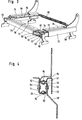
- Base rails 50 and 56 are shown, with base rail 50 shown in greater detail with the understanding that base rail 56 is a mirror image of base rail 50.
- Base rail 50 is an elongated structural member of a generally channel shaped cross section comprising base section 51 with bottom leg section 52 and top leg section 54 extending inwardly therefrom.
- Base section 51 has mounting brackets 58, 60 mounted thereto which in turn are adapted to be mounted to the floor or frame of a vehicle.
- Mounting brackets 58, 60 can be of various shapes depending on the vehicle mounting requirements.
- Base rails 50, 56 are parallel to each other with their respective leg sections extending inwardly toward each other.
- Seat track 61 is a single assembly comprising parallel side elements 64, 66 joined at their ends by front element 62.
- Parallel side elements 64, 66 are mirror images of each other, and side element 64 will be described in detail as it is also shown in Figure 4.
- Side track side element 64 is an elongated structrual element of a generally channel shaped cross section.
- Side element 64 comprises a base section 71 from which top leg section 67 and bottom leg section 65 extend perpendicularly thereby forming a channel type cross section.
- An elongated, generally angle shaped in cross section seat frame 70 is affixed to top leg section 67 of side element 64.
- a leg 73 forms part of seat frame 70 that extends parallel to base section 71 of side element 64.
- An elongated, generally angle shaped in cross section seat frame 72 is affixed to top leg section of front element 62.
- a leg 75 forms one angle section of seat frame 72.
- An elongated, generally angle shaped in cross section seat frame 74 is affixed to top leg section of side element 66.
- a leg similar to leg 73 forms an angle section of seat frame 74. All of seat frames 70, 72 and 74 have holes in their top surfaces adapted to receive the ends of seat support springs 80.
- the edges of legs 73, 75 and the leg of seat frame 74 are all adapted to receive a hook affixed to a seat cover for the vehicle seat.
- Seat track 61 is adapted to fit over base rails 50, 56.
- Ball bearings 82 are located between an indentation running the length of bottom leg 52 of rail 50 and an indentation running the length of bottom leg 65 of side elements 64.
- Ball bearings 84 are located between an indentation running the length of top leg section 67 of seat track side element 64 and top leg section 54 of base rail 50. Such ball bearings assure the rolling of seat frame 61 along base rails 50, 56.
Landscapes
- Engineering & Computer Science (AREA)
- Aviation & Aerospace Engineering (AREA)
- Transportation (AREA)
- Mechanical Engineering (AREA)
- Seats For Vehicles (AREA)
Applications Claiming Priority (2)
| Application Number | Priority Date | Filing Date | Title |
|---|---|---|---|
| US649191 | 1984-09-10 | ||
| US06/649,191 US4601517A (en) | 1984-09-10 | 1984-09-10 | Integral seat frame and track |
Publications (2)
| Publication Number | Publication Date |
|---|---|
| EP0175110A1 true EP0175110A1 (fr) | 1986-03-26 |
| EP0175110B1 EP0175110B1 (fr) | 1988-06-01 |
Family
ID=24603798
Family Applications (1)
| Application Number | Title | Priority Date | Filing Date |
|---|---|---|---|
| EP85109736A Expired EP0175110B1 (fr) | 1984-09-10 | 1985-08-02 | Bâti et support de siège intégré |
Country Status (3)
| Country | Link |
|---|---|
| US (1) | US4601517A (fr) |
| EP (1) | EP0175110B1 (fr) |
| DE (1) | DE3563013D1 (fr) |
Cited By (1)
| Publication number | Priority date | Publication date | Assignee | Title |
|---|---|---|---|---|
| FR2686049A1 (fr) * | 1992-01-10 | 1993-07-16 | Renault | Support reglable de coussin de siege de vehicule automobile. |
Families Citing this family (15)
| Publication number | Priority date | Publication date | Assignee | Title |
|---|---|---|---|---|
| JPH0685829B2 (ja) * | 1985-09-30 | 1994-11-02 | アイシン精機株式会社 | 自動車用シ−ト |
| DE3633012C2 (de) * | 1985-09-30 | 1994-06-23 | Aisin Seiki | Polstersitz für Kraftfahrzeuge |
| US5209447A (en) * | 1991-11-15 | 1993-05-11 | Tachi-S Co., Ltd. | Cover structure for slide rail in seat adjuster |
| JP2507946Y2 (ja) * | 1992-02-25 | 1996-08-21 | 池田物産株式会社 | シ―トのスライドレ―ル構造 |
| US5228659A (en) * | 1992-08-10 | 1993-07-20 | Hoover Universal, Inc. | Vehicle seat assembly with extending seat track trim cover |
| US5280987A (en) * | 1993-03-10 | 1994-01-25 | General Motors Corporation | In-floor seat adjuster |
| US5407166A (en) * | 1993-11-17 | 1995-04-18 | General Motors Corporation | Vehicle seat track assembly |
| US6010195A (en) * | 1995-11-27 | 2000-01-04 | Lear Corporation | Automotive modular seat frame assembly |
| US6199252B1 (en) | 1995-11-27 | 2001-03-13 | Lear Corporation | Modular seat assembly and method of installing the same within a vehicle |
| JP4006495B2 (ja) * | 2001-08-01 | 2007-11-14 | 日野自動車株式会社 | 車両用シート構造 |
| US20030151294A1 (en) * | 2002-02-13 | 2003-08-14 | Glater Irving W. | Interchangeable seat cushions for automotive bucket seats |
| US6817673B2 (en) | 2002-04-17 | 2004-11-16 | Lear Corporation | Vehicle seat assembly |
| US7581792B2 (en) * | 2005-06-07 | 2009-09-01 | Lear Corporation | Vehicle seat frame structure and method of assembling a portion of a vehicle seat frame |
| US7866689B2 (en) * | 2005-08-19 | 2011-01-11 | Lear Corporation | Vehicle seat frame structure and method of manufacturing same |
| US10479245B2 (en) * | 2016-10-25 | 2019-11-19 | Ford Global Technologies, Llc | Bracket subassembly and seat assembly |
Citations (2)
| Publication number | Priority date | Publication date | Assignee | Title |
|---|---|---|---|---|
| FR2371313A1 (fr) * | 1976-03-29 | 1978-06-16 | Faure Bertrand | Glissiere de siege pour vehicule |
| DE3143118A1 (de) * | 1981-10-30 | 1983-05-11 | Adam Opel AG, 6090 Rüsselsheim | Kraftfahrzeugsitz |
Family Cites Families (5)
| Publication number | Priority date | Publication date | Assignee | Title |
|---|---|---|---|---|
| BR7906056A (pt) * | 1978-09-23 | 1980-05-27 | Keiper Automobiltechnik Gmbh | Dispositivo para o ajuste de inclinacao de assentos principalmente de assentos de automoveis |
| DE2852230A1 (de) * | 1978-12-02 | 1980-06-12 | Lautenschlaeger Kg Karl | Ausziehfuehrung fuer schubladen u.dgl. |
| IT1118739B (it) * | 1979-06-01 | 1986-03-03 | Lifel Di Torta Mario & C Sas | Dispositivo di sopporto e di guida per sedili regolabili di autoveicoli |
| US4492408A (en) * | 1982-01-19 | 1985-01-08 | Allen Industries, Inc. | Vehicle seat construction and method of making the same |
| JPS58126227A (ja) * | 1982-01-21 | 1983-07-27 | Nissan Motor Co Ltd | 自動車用シ−トスライド装置 |
-
1984
- 1984-09-10 US US06/649,191 patent/US4601517A/en not_active Expired - Fee Related
-
1985
- 1985-08-02 DE DE8585109736T patent/DE3563013D1/de not_active Expired
- 1985-08-02 EP EP85109736A patent/EP0175110B1/fr not_active Expired
Patent Citations (2)
| Publication number | Priority date | Publication date | Assignee | Title |
|---|---|---|---|---|
| FR2371313A1 (fr) * | 1976-03-29 | 1978-06-16 | Faure Bertrand | Glissiere de siege pour vehicule |
| DE3143118A1 (de) * | 1981-10-30 | 1983-05-11 | Adam Opel AG, 6090 Rüsselsheim | Kraftfahrzeugsitz |
Non-Patent Citations (1)
| Title |
|---|
| PATENT ABSTRACTS OF JAPAN, vol. 5, no. 170 (M-94)[842], 29th October 1981; & JP-A-56 095 730 (TACHIKAWA SPRING K.K.) 03-08-1981 * |
Cited By (1)
| Publication number | Priority date | Publication date | Assignee | Title |
|---|---|---|---|---|
| FR2686049A1 (fr) * | 1992-01-10 | 1993-07-16 | Renault | Support reglable de coussin de siege de vehicule automobile. |
Also Published As
| Publication number | Publication date |
|---|---|
| DE3563013D1 (en) | 1988-07-07 |
| US4601517A (en) | 1986-07-22 |
| EP0175110B1 (fr) | 1988-06-01 |
Similar Documents
| Publication | Publication Date | Title |
|---|---|---|
| EP0175110A1 (fr) | Bâti et support de siège intégré | |
| US5529376A (en) | Vehicle seat assembly | |
| US4756503A (en) | Slide device for an automotive seat | |
| US8544796B2 (en) | Passenger seat assembly with associated floor panel and aircraft sidewall attachment, and method | |
| US7195319B2 (en) | Reclining chair | |
| US4969622A (en) | Support for seats of automotive vehicles | |
| JPH07505592A (ja) | 自動車用のシートトラック | |
| EP0053012A1 (fr) | Cadre pour siège de passagers multiplace | |
| US4725032A (en) | Seat slide adjuster for vehicles | |
| US4597552A (en) | Seat adjuster | |
| GB2215994A (en) | Vehicle seat adjuster slide assembly | |
| US6089665A (en) | Load transfer structural member for a seat assembly | |
| JPH07329616A (ja) | 自動車用シートスライド装置 | |
| US4422691A (en) | Passenger seat | |
| US6065795A (en) | Seating arrangement for a motor vehicle | |
| US7111906B2 (en) | Flexible seat mount for chair seat bottom | |
| GB2218331A (en) | Passenger seat for motor vehicle | |
| JPH05139303A (ja) | 鉄道車両 | |
| EP0135389A3 (fr) | Ensemble de siège de véhicule à glissière intégrée | |
| US3475054A (en) | Seat construction | |
| US2261504A (en) | Adjustable support | |
| US6405987B1 (en) | Reinforcement member for a seat mounting assembly | |
| GB1572695A (en) | Vehicle seat | |
| JP3378217B2 (ja) | シートスライド装置のレール体構造 | |
| US4392692A (en) | Seat support slide track structure |
Legal Events
| Date | Code | Title | Description |
|---|---|---|---|
| PUAI | Public reference made under article 153(3) epc to a published international application that has entered the european phase |
Free format text: ORIGINAL CODE: 0009012 |
|
| 17P | Request for examination filed |
Effective date: 19850802 |
|
| AK | Designated contracting states |
Kind code of ref document: A1 Designated state(s): DE FR GB IT |
|
| RAP1 | Party data changed (applicant data changed or rights of an application transferred) |
Owner name: ITT INDUSTRIES INC. |
|
| 17Q | First examination report despatched |
Effective date: 19861029 |
|
| D17Q | First examination report despatched (deleted) | ||
| ITF | It: translation for a ep patent filed | ||
| GRAA | (expected) grant |
Free format text: ORIGINAL CODE: 0009210 |
|
| AK | Designated contracting states |
Kind code of ref document: B1 Designated state(s): DE FR GB IT |
|
| REF | Corresponds to: |
Ref document number: 3563013 Country of ref document: DE Date of ref document: 19880707 |
|
| ET | Fr: translation filed | ||
| PLBE | No opposition filed within time limit |
Free format text: ORIGINAL CODE: 0009261 |
|
| STAA | Information on the status of an ep patent application or granted ep patent |
Free format text: STATUS: NO OPPOSITION FILED WITHIN TIME LIMIT |
|
| PG25 | Lapsed in a contracting state [announced via postgrant information from national office to epo] |
Ref country code: DE Effective date: 19890503 |
|
| 26N | No opposition filed | ||
| ITTA | It: last paid annual fee | ||
| PGFP | Annual fee paid to national office [announced via postgrant information from national office to epo] |
Ref country code: GB Payment date: 20010725 Year of fee payment: 17 |
|
| PGFP | Annual fee paid to national office [announced via postgrant information from national office to epo] |
Ref country code: FR Payment date: 20010820 Year of fee payment: 17 |
|
| REG | Reference to a national code |
Ref country code: GB Ref legal event code: IF02 |
|
| PG25 | Lapsed in a contracting state [announced via postgrant information from national office to epo] |
Ref country code: GB Free format text: LAPSE BECAUSE OF NON-PAYMENT OF DUE FEES Effective date: 20020802 |
|
| GBPC | Gb: european patent ceased through non-payment of renewal fee |
Effective date: 20020802 |
|
| PG25 | Lapsed in a contracting state [announced via postgrant information from national office to epo] |
Ref country code: FR Free format text: LAPSE BECAUSE OF NON-PAYMENT OF DUE FEES Effective date: 20030430 |
|
| REG | Reference to a national code |
Ref country code: FR Ref legal event code: ST |