EP0175493B1 - Dispositif de ceinture de sécurité pour véhicules - Google Patents
Dispositif de ceinture de sécurité pour véhicules Download PDFInfo
- Publication number
- EP0175493B1 EP0175493B1 EP85305960A EP85305960A EP0175493B1 EP 0175493 B1 EP0175493 B1 EP 0175493B1 EP 85305960 A EP85305960 A EP 85305960A EP 85305960 A EP85305960 A EP 85305960A EP 0175493 B1 EP0175493 B1 EP 0175493B1
- Authority
- EP
- European Patent Office
- Prior art keywords
- arm
- seat belt
- seat
- arm portion
- reach
- Prior art date
- Legal status (The legal status is an assumption and is not a legal conclusion. Google has not performed a legal analysis and makes no representation as to the accuracy of the status listed.)
- Expired
Links
- 210000000245 forearm Anatomy 0.000 claims description 17
- 230000035939 shock Effects 0.000 description 2
- 230000003187 abdominal effect Effects 0.000 description 1
- 230000000694 effects Effects 0.000 description 1
Images

Classifications
-
- B—PERFORMING OPERATIONS; TRANSPORTING
- B60—VEHICLES IN GENERAL
- B60R—VEHICLES, VEHICLE FITTINGS, OR VEHICLE PARTS, NOT OTHERWISE PROVIDED FOR
- B60R22/00—Safety belts or body harnesses in vehicles
- B60R22/02—Semi-passive restraint systems, e.g. systems applied or removed automatically but not both ; Manual restraint systems
- B60R22/03—Means for presenting the belt or part thereof to the wearer, e.g. foot-operated
Definitions
- This invention relates to a three-point support seat belt device for a vehicle, particularly, for a vehicle in which a front seat and a rear seat are arranged within a compartment in a longitudinal direction of the vehicle.
- a seat belt device is disclosed, for example, in Japanese Patent Application Laid-Open No. 94,120/73 in which a reach arm is supported on one side of a seat within the compartment so that the reach arm may swing back and forth, and a seat belt which is drawn out from a retractor is attached to an end of the reach arm, whereby when the seat belt is to be worn, the reach arm is swung forwardly so as to guide the seat belt to the place near the hand of an occupant seated on the front seat.
- a seat belt device for a vehicle in which a front seat and a rear seat are arranged within a compartment in a longitudinal direction of the vehicle, the device comprising a reach arm provided at one side of the front seat so as to be swingable back and forth, a seat belt drawn out from a retractor and attached to a fore end of the reach arm, and a through-tang mounted on the seat belt and capable of being detachably connected to a buckle provided at the other side of the front seat, characterised in'that said reach arm is divided into a base arm portion supported at said one side of the front seat for swing motion back and forth and a fore arm portion mounted on the seat belt, said base arm portion and said fore arm portion being connected together so as to be foldable at a connection therebetween in the swinging direction of the reach arm, a restriction mechanism being provided between said base arm portion and said fore arm portion for restricting said base and fore arm portions to assume a straight state when the reach arm is swung to an operative position forward
- the reach arm can be formed to have a desired length so that the seat belt can be worn very easily.
- the reach arm When the reach arm is brought to its non-used or inoperative position, it can be folded to the back of the front seat in a compacted configuration.
- the reach arm does not interfere with the rear seat and does not disturb a person in getting on and off the rear seat.
- a seat belt device in which when the seat belt is not in use, the reach arm can be housed compactly; when the seat belt is to be used, the reach arm can project forwardly to let the seat belt occupy a position where the belt can be worn most easily; and when the seat belt is in use and a great shock is applied thereto, the device can effectively cope with such shock.
- front seat 4 and the rear seat 5 are shown longitudinally arranged on a floor surface 3 within a compartment 2 of a vehicle body 1.
- the front seat 4 can be slidably moved back and forth on a guide rail means 6 on the floor surface 3.
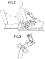
- a bendable reach arm R Externally of a seat portion 4a of the front seat 4, i.e., on one side thereof near an opening and closing door 7 is provided the base end of a bendable reach arm R so as to be swingable back and forth.
- the reach arm R is divided into a base arm portion 8 and a fore arm portion 9.
- a base end of the base arm portion 8 is pivoted at 11 on a frame 10 provided on the one side of the seat portion 4a of the front seat 4 so that the base arm portion 8 can swing back and forth.
- a driving device 12 such as an electric motor is provided on the frame 10 and is connected to the base arm portion 8, and by actuation of the driving device 12 the base arm portion 8 is driven to swing back and forth as indicated by the arrow A in Figure 1.
- a stopper pin 13 projecting from the base of the base arm portion 8 is fitted into an arcuate hole 14 in the frame 10, whereby a swing angle of the base arm portion 8 is defined.
- the base end of the fore arm portion 9 is connected to the free end of the base arm portion 8 via a pivot shaft 15 in a manner such that the fore arm portion 9 can be folded about the shaft 15 in the swinging direction of the base arm portion 8.
- a belt connecting hole 16 is provided on the fore end of the fore arm portion 9, and the end of a seat belt B is attached to the belt connecting hole 16.
- restriction mechanism 17 which restricts both the arm portions so that these portions stretch straight when the reach arm R is swung forwardly of the front seat 4.
- This restriction mechanism 17 comprises an engaging shoulder 18 formed on the fore end of the base arm portion 8 and an engaging projection 19 formed on the base end of the fore arm portion 9. The said shoulder and projection are brought into engagement with each other by tension of the seat belt B, when the reach arm R is moved forwardly of the front seat 4, to hold the reach arm in its straight condition.
- a retractor 21 is provided at the lower portion of a wall 20 of the compartment.
- the seat belt B drawn from the retractor 21 extends upwardly along the wall 20 and is pulled out inwardly of the compartment 2 through a guide roller 22 and a guide ring 23 which are provided on the wall 20, and the free end of the seat belt B is attached to the belt connecting hole 16 at the fore end of the reach arm R as already mentioned.
- a through-tang 24 is slidably disposed on the seat belt B between the guide ring 23 and the reach arm R.
- An engaging hole 25 is provided at one side of the through-tang 24.
- a support arm 26 obliquely forwardly projects on the other side of the front seat 4 near a central portion within the compartment 2.
- a buckle 27 is attached to the front end of the support arm 26.
- the engaging hole 25 of the through-tang 24 can be detachably connected to the buckle 27.
- the reach arm R stays housed rearwardly of the front seat4. In this state, the reach arm R is bent or folded as shown by the chain lines in Figures 1 and 2 and by the solid line in Figure 3 and stays between the front and rear seats 4 and 5 compactly without disturbing an occupant.
- the base arm portion 8 of the reach arm R When an occupant seated on the front seat 4 wishes to wear the seat belt B, by actuating the driving device 12, the base arm portion 8 of the reach arm R is swung forwardly. As the base arm portion 8 swings forwardly, the fore arm portion 9 is applied with rearward tension caused by the seat belt B so that the fore arm portion 9 is rearwardly turned around the pivot shaft 15 as shown by the arrow C of Fig. 3. Then when the reach arm R is swung to its operative position forwardly of the front seat 4 as shown by the solid lines in Figs. 1 and 2, the engaging shoulder 18 and the engaging projection 19 are brought into engagement with each other under the action of the tension of the seat belt B and the reach arm R assumes its stretched straight state.
- the seat belt B attached to the connecting hole 16 at the fore end of the reach arm R is then guided to the place near the hand of the occupant on the front seat 4. Now the occupant can pull the through-tang 24 inserted through the seat belt B while sliding the through-tang 24 along the seat belt B to engage the engaging hole 25 with the buckle 27.
- the seat belt B can be worn by the occupant seated on the front seat 4.
- the seat belt device is of the three-point support type, the seat belt B extends diagonally obliquely from the shoulder toward the waist of the occupant and further extends laterally along an abdominal portion of the occupant.
- the base arm portion 8 of the reach arm R may be supported directly on the vehicle body sideways of the front seat 4.
Landscapes
- Engineering & Computer Science (AREA)
- Mechanical Engineering (AREA)
- Automotive Seat Belt Assembly (AREA)
Claims (3)
Applications Claiming Priority (6)
| Application Number | Priority Date | Filing Date | Title |
|---|---|---|---|
| JP175650/84 | 1984-08-23 | ||
| JP59175651A JPS6181846A (ja) | 1984-08-23 | 1984-08-23 | 車両のシ−トベルト装置 |
| JP59175650A JPS6181845A (ja) | 1984-08-23 | 1984-08-23 | 車両のシ−トベルト装置 |
| JP175651/84 | 1984-08-23 | ||
| JP59182056A JPS6181848A (ja) | 1984-08-31 | 1984-08-31 | 車両のシ−トベルト装置 |
| JP182056/84 | 1984-08-31 |
Related Child Applications (1)
| Application Number | Title | Priority Date | Filing Date |
|---|---|---|---|
| EP19890200564 Division-Into EP0323877B1 (fr) | 1984-08-23 | 1985-08-22 | Ceinture de sécurité pour véhicule |
Publications (3)
| Publication Number | Publication Date |
|---|---|
| EP0175493A2 EP0175493A2 (fr) | 1986-03-26 |
| EP0175493A3 EP0175493A3 (en) | 1987-09-02 |
| EP0175493B1 true EP0175493B1 (fr) | 1990-01-24 |
Family
ID=27324145
Family Applications (1)
| Application Number | Title | Priority Date | Filing Date |
|---|---|---|---|
| EP85305960A Expired EP0175493B1 (fr) | 1984-08-23 | 1985-08-22 | Dispositif de ceinture de sécurité pour véhicules |
Country Status (3)
| Country | Link |
|---|---|
| US (2) | US4643449A (fr) |
| EP (1) | EP0175493B1 (fr) |
| DE (2) | DE3586760T2 (fr) |
Families Citing this family (13)
| Publication number | Priority date | Publication date | Assignee | Title |
|---|---|---|---|---|
| JPH0321315Y2 (fr) * | 1984-11-02 | 1991-05-09 | ||
| JPH02121364U (fr) * | 1989-03-13 | 1990-10-02 | ||
| GB2235362B (en) * | 1989-08-30 | 1993-11-10 | Bsrd Ltd | Seat belt presenters |
| JPH04103451A (ja) * | 1990-08-23 | 1992-04-06 | Takata Kk | シートベルトリーチャ装置 |
| FR2692533A1 (fr) * | 1992-06-23 | 1993-12-24 | Renault | Dispositif de commande d'un bras de présentation d'une languette de verrouillage montée sur une sangle de ceinture de sécurité. |
| DE4339358C2 (de) * | 1992-12-17 | 1996-02-22 | Ford Werke Ag | Baugruppe zur Verankerung von Sicherheitsgurten |
| US5730499A (en) * | 1995-09-29 | 1998-03-24 | Ford Global Technologies, Inc. | Adjustable guide assembly for a vehicle seat belt system |
| JP4356601B2 (ja) * | 2004-12-14 | 2009-11-04 | トヨタ自動車株式会社 | ウエビングガイド機構 |
| US7445244B2 (en) * | 2006-03-27 | 2008-11-04 | Ford Global Technologies, Llc | Seat belt anchor |
| KR101305812B1 (ko) | 2011-10-05 | 2013-09-06 | 아우토리브 디벨롭먼트 아베 | 차량용 시트벨트의 웨빙가이드 회전장치 및 그 회전 제어방법 |
| DE102012010230B4 (de) * | 2012-05-24 | 2014-01-09 | Faurecia Autositze Gmbh | Montagevorrichtung zur Befestigung eines Gurtschlosses |
| JP2014148270A (ja) * | 2013-02-01 | 2014-08-21 | Autoliv Development Ab | シートベルト装置 |
| US10059237B2 (en) * | 2016-10-28 | 2018-08-28 | Toyota Motor Engineering & Manufacturing North America, Inc. | Vehicle seat armrest with retractable arm support portion |
Family Cites Families (12)
| Publication number | Priority date | Publication date | Assignee | Title |
|---|---|---|---|---|
| JPS4894120A (fr) * | 1972-03-16 | 1973-12-04 | ||
| FR2209341A6 (fr) * | 1972-12-04 | 1974-06-28 | Ferodo Sa | |
| US3841659A (en) * | 1973-12-26 | 1974-10-15 | Ford Motor Co | Vehicular three-point seat belt system |
| FR2343627A1 (fr) * | 1976-03-15 | 1977-10-07 | Honda Motor Co Ltd | Dispositif de retenue pour ceintures de securite de vehicules automobiles |
| BE856425A (fr) * | 1977-03-26 | 1977-10-31 | Hansaliv Gurte G M B H & Co K | Dispositif de retenue pour ceintures de securite |
| SE413071B (sv) * | 1977-04-20 | 1980-04-14 | Lindblad Stig Martin | Anordning vid sekerhetsbelten for fordon |
| DE2730081C2 (de) * | 1977-07-02 | 1982-04-08 | Daimler-Benz Ag, 7000 Stuttgart | Anordnung eines Dreipunkt-Automatikgurtes |
| JPS5713356U (fr) * | 1980-06-27 | 1982-01-23 | ||
| JPS57159549U (fr) * | 1981-03-30 | 1982-10-06 | ||
| US4496170A (en) * | 1981-09-30 | 1985-01-29 | Honda Giken Kogyo Kabushiki Kaisha | Seat belt device for vehicles |
| SE449198B (sv) * | 1983-01-27 | 1987-04-13 | Stil Ind Ab | Anordning vid las till bilbelte |
| JPS59149841A (ja) * | 1983-02-17 | 1984-08-27 | Honda Motor Co Ltd | シ−トベルトの装着補助装置 |
-
1985
- 1985-08-20 US US06/767,531 patent/US4643449A/en not_active Expired - Lifetime
- 1985-08-22 EP EP85305960A patent/EP0175493B1/fr not_active Expired
- 1985-08-22 DE DE8989200564T patent/DE3586760T2/de not_active Expired - Fee Related
- 1985-08-22 DE DE8585305960T patent/DE3575541D1/de not_active Expired - Lifetime
-
1986
- 1986-09-29 US US06/912,470 patent/US4697827A/en not_active Expired - Fee Related
Also Published As
| Publication number | Publication date |
|---|---|
| EP0175493A3 (en) | 1987-09-02 |
| EP0175493A2 (fr) | 1986-03-26 |
| DE3586760D1 (de) | 1992-11-19 |
| US4643449A (en) | 1987-02-17 |
| US4697827A (en) | 1987-10-06 |
| DE3575541D1 (de) | 1990-03-01 |
| DE3586760T2 (de) | 1993-03-04 |
Similar Documents
| Publication | Publication Date | Title |
|---|---|---|
| EP0175493B1 (fr) | Dispositif de ceinture de sécurité pour véhicules | |
| US5022677A (en) | Motor vehicle seat featuring two seat belts | |
| JP3869857B2 (ja) | セーフティベルト用構造 | |
| JPH0142858B2 (fr) | ||
| US4258933A (en) | Movable inboard belt guide for use in passive vehicle occupant restraint systems | |
| US4405155A (en) | Seat belt device for an automotive vehicle | |
| EP0411809B1 (fr) | Montage d'une ceinture de sécurité pour véhicule | |
| JP4345431B2 (ja) | アームレスト付きシート | |
| EP0323877B1 (fr) | Ceinture de sécurité pour véhicule | |
| JPH11170973A (ja) | 車両用シートベルト装置 | |
| JPS63222957A (ja) | 自動車のシ−トベルト装置 | |
| JPH0721417Y2 (ja) | シートベルトガイド構造 | |
| KR0124363Y1 (ko) | 자동차용 후방 시트의 안전 벨트 버클 수납 장치 | |
| JPS6181845A (ja) | 車両のシ−トベルト装置 | |
| JPS59179435A (ja) | シ−トベルト装置 | |
| JPH03550A (ja) | 自動車のシートベルト装置 | |
| KR920005587Y1 (ko) | 자동 안동벨트 장치용 계지구 | |
| SE507011C2 (sv) | Bältesförare för styrning av ett i ett motorfordon anordnat säkerhetsbältesband | |
| KR950007333Y1 (ko) | 일부 텐션기능이 있는 자동차의 시트벨트버클 어셈블리 | |
| KR200154536Y1 (ko) | 차량용 시트벨트 | |
| JPS609085Y2 (ja) | パツシブシ−トベルト装置 | |
| EP0039176B1 (fr) | Système de ceinture de sécurité passive | |
| JPS6340046Y2 (fr) | ||
| JPS6181846A (ja) | 車両のシ−トベルト装置 | |
| KR100366591B1 (ko) | 자동차용 이동식 시트 벨트 구조 |
Legal Events
| Date | Code | Title | Description |
|---|---|---|---|
| PUAI | Public reference made under article 153(3) epc to a published international application that has entered the european phase |
Free format text: ORIGINAL CODE: 0009012 |
|
| AK | Designated contracting states |
Kind code of ref document: A2 Designated state(s): DE FR GB |
|
| PUAL | Search report despatched |
Free format text: ORIGINAL CODE: 0009013 |
|
| AK | Designated contracting states |
Kind code of ref document: A3 Designated state(s): DE FR GB |
|
| 17P | Request for examination filed |
Effective date: 19870908 |
|
| 17Q | First examination report despatched |
Effective date: 19880831 |
|
| GRAA | (expected) grant |
Free format text: ORIGINAL CODE: 0009210 |
|
| AK | Designated contracting states |
Kind code of ref document: B1 Designated state(s): DE FR GB |
|
| XX | Miscellaneous (additional remarks) |
Free format text: TEILANMELDUNG 89200564.6 EINGEREICHT AM 22/08/85. |
|
| REF | Corresponds to: |
Ref document number: 3575541 Country of ref document: DE Date of ref document: 19900301 |
|
| ET | Fr: translation filed | ||
| PLBE | No opposition filed within time limit |
Free format text: ORIGINAL CODE: 0009261 |
|
| STAA | Information on the status of an ep patent application or granted ep patent |
Free format text: STATUS: NO OPPOSITION FILED WITHIN TIME LIMIT |
|
| 26N | No opposition filed | ||
| PGFP | Annual fee paid to national office [announced via postgrant information from national office to epo] |
Ref country code: FR Payment date: 19920807 Year of fee payment: 8 |
|
| PG25 | Lapsed in a contracting state [announced via postgrant information from national office to epo] |
Ref country code: FR Effective date: 19940429 |
|
| REG | Reference to a national code |
Ref country code: FR Ref legal event code: ST |
|
| PGFP | Annual fee paid to national office [announced via postgrant information from national office to epo] |
Ref country code: GB Payment date: 19980813 Year of fee payment: 14 |
|
| PGFP | Annual fee paid to national office [announced via postgrant information from national office to epo] |
Ref country code: DE Payment date: 19980831 Year of fee payment: 14 |
|
| PG25 | Lapsed in a contracting state [announced via postgrant information from national office to epo] |
Ref country code: GB Free format text: LAPSE BECAUSE OF NON-PAYMENT OF DUE FEES Effective date: 19990822 |
|
| GBPC | Gb: european patent ceased through non-payment of renewal fee |
Effective date: 19990822 |
|
| PG25 | Lapsed in a contracting state [announced via postgrant information from national office to epo] |
Ref country code: DE Free format text: LAPSE BECAUSE OF NON-PAYMENT OF DUE FEES Effective date: 20000601 |