EP0175794A1 - Foyer individuel pour combustibles solides - Google Patents
Foyer individuel pour combustibles solides Download PDFInfo
- Publication number
- EP0175794A1 EP0175794A1 EP84110142A EP84110142A EP0175794A1 EP 0175794 A1 EP0175794 A1 EP 0175794A1 EP 84110142 A EP84110142 A EP 84110142A EP 84110142 A EP84110142 A EP 84110142A EP 0175794 A1 EP0175794 A1 EP 0175794A1
- Authority
- EP
- European Patent Office
- Prior art keywords
- grate
- filling chamber
- fireplace according
- filling
- loading chamber
- Prior art date
- Legal status (The legal status is an assumption and is not a legal conclusion. Google has not performed a legal analysis and makes no representation as to the accuracy of the status listed.)
- Withdrawn
Links
- 239000004449 solid propellant Substances 0.000 title claims abstract description 7
- 239000000446 fuel Substances 0.000 claims abstract description 48
- 238000002485 combustion reaction Methods 0.000 claims abstract description 21
- 239000003245 coal Substances 0.000 claims abstract description 7
- 238000010304 firing Methods 0.000 claims description 11
- 230000005540 biological transmission Effects 0.000 claims description 3
- 239000003779 heat-resistant material Substances 0.000 claims description 3
- 238000009434 installation Methods 0.000 claims description 3
- 230000033001 locomotion Effects 0.000 claims description 3
- XLYOFNOQVPJJNP-UHFFFAOYSA-N water Substances O XLYOFNOQVPJJNP-UHFFFAOYSA-N 0.000 claims 1
- 239000007789 gas Substances 0.000 abstract description 22
- 239000002023 wood Substances 0.000 abstract description 3
- 239000002912 waste gas Substances 0.000 abstract 5
- 239000002351 wastewater Substances 0.000 abstract 1
- 238000013461 design Methods 0.000 description 4
- 238000006243 chemical reaction Methods 0.000 description 3
- 239000000463 material Substances 0.000 description 3
- 238000012546 transfer Methods 0.000 description 3
- 239000003344 environmental pollutant Substances 0.000 description 2
- 230000003628 erosive effect Effects 0.000 description 2
- JEIPFZHSYJVQDO-UHFFFAOYSA-N iron(III) oxide Inorganic materials O=[Fe]O[Fe]=O JEIPFZHSYJVQDO-UHFFFAOYSA-N 0.000 description 2
- 238000012986 modification Methods 0.000 description 2
- 230000004048 modification Effects 0.000 description 2
- 239000003415 peat Substances 0.000 description 2
- 231100000719 pollutant Toxicity 0.000 description 2
- 230000001105 regulatory effect Effects 0.000 description 2
- 239000000779 smoke Substances 0.000 description 2
- 238000003860 storage Methods 0.000 description 2
- RNFJDJUURJAICM-UHFFFAOYSA-N 2,2,4,4,6,6-hexaphenoxy-1,3,5-triaza-2$l^{5},4$l^{5},6$l^{5}-triphosphacyclohexa-1,3,5-triene Chemical compound N=1P(OC=2C=CC=CC=2)(OC=2C=CC=CC=2)=NP(OC=2C=CC=CC=2)(OC=2C=CC=CC=2)=NP=1(OC=1C=CC=CC=1)OC1=CC=CC=C1 RNFJDJUURJAICM-UHFFFAOYSA-N 0.000 description 1
- OKTJSMMVPCPJKN-UHFFFAOYSA-N Carbon Chemical compound [C] OKTJSMMVPCPJKN-UHFFFAOYSA-N 0.000 description 1
- 230000009471 action Effects 0.000 description 1
- 238000003915 air pollution Methods 0.000 description 1
- QVGXLLKOCUKJST-UHFFFAOYSA-N atomic oxygen Chemical compound [O] QVGXLLKOCUKJST-UHFFFAOYSA-N 0.000 description 1
- 229910052799 carbon Inorganic materials 0.000 description 1
- 229910010293 ceramic material Inorganic materials 0.000 description 1
- 238000010276 construction Methods 0.000 description 1
- 238000011161 development Methods 0.000 description 1
- 238000009826 distribution Methods 0.000 description 1
- 238000000605 extraction Methods 0.000 description 1
- 239000003063 flame retardant Substances 0.000 description 1
- 239000003546 flue gas Substances 0.000 description 1
- 230000020169 heat generation Effects 0.000 description 1
- 238000010438 heat treatment Methods 0.000 description 1
- 229930195733 hydrocarbon Natural products 0.000 description 1
- 150000002430 hydrocarbons Chemical class 0.000 description 1
- 239000003077 lignite Substances 0.000 description 1
- 230000007774 longterm Effects 0.000 description 1
- 230000007246 mechanism Effects 0.000 description 1
- 238000000034 method Methods 0.000 description 1
- 229910052760 oxygen Inorganic materials 0.000 description 1
- 239000001301 oxygen Substances 0.000 description 1
- 238000003825 pressing Methods 0.000 description 1
- 230000008569 process Effects 0.000 description 1
- 230000007480 spreading Effects 0.000 description 1
- 238000003892 spreading Methods 0.000 description 1
- 230000001360 synchronised effect Effects 0.000 description 1
- 238000012360 testing method Methods 0.000 description 1
- 238000011144 upstream manufacturing Methods 0.000 description 1
Images



Classifications
-
- F—MECHANICAL ENGINEERING; LIGHTING; HEATING; WEAPONS; BLASTING
- F24—HEATING; RANGES; VENTILATING
- F24B—DOMESTIC STOVES OR RANGES FOR SOLID FUELS; IMPLEMENTS FOR USE IN CONNECTION WITH STOVES OR RANGES
- F24B1/00—Stoves or ranges
- F24B1/02—Closed stoves
- F24B1/026—Closed stoves with several combustion zones
-
- F—MECHANICAL ENGINEERING; LIGHTING; HEATING; WEAPONS; BLASTING
- F24—HEATING; RANGES; VENTILATING
- F24B—DOMESTIC STOVES OR RANGES FOR SOLID FUELS; IMPLEMENTS FOR USE IN CONNECTION WITH STOVES OR RANGES
- F24B13/00—Details solely applicable to stoves or ranges burning solid fuels
- F24B13/02—Arrangement or mountings of fire-grate assemblies; Arrangement or mountings of linings for fire-boxes, e.g. fire-backs
-
- F—MECHANICAL ENGINEERING; LIGHTING; HEATING; WEAPONS; BLASTING
- F24—HEATING; RANGES; VENTILATING
- F24B—DOMESTIC STOVES OR RANGES FOR SOLID FUELS; IMPLEMENTS FOR USE IN CONNECTION WITH STOVES OR RANGES
- F24B13/00—Details solely applicable to stoves or ranges burning solid fuels
- F24B13/04—Arrangements for feeding solid fuel, e.g. hoppers
Definitions
- the invention relates to a single fireplace for solid fuels according to the preamble of the main claim.
- a further disadvantage lies in the difficulty in igniting the fuel, because the fuel has to be introduced into the filling space before the ignition, and thus the rust, especially from above flame retardant coal is covered.
- the known solution there is the danger that fuel which is in reaction remains on the refilled filling floor and that a burnout in the filling chamber is set in motion with the slightest leak.
- DE-PS 191 357 it is known to give pourable fuel from above into a telescopic trolley arranged laterally next to a fire grate, which is open on the grate side and can be gradually pushed together towards the grate via a rod connected to the rear wall of the trolley, so that the fuel falls freely and uncontrolled onto the grate of a conventional furnace, where it burns uncontrolled according to the burn-through principle.
- a telescopic trolley arranged laterally next to a fire grate, which is open on the grate side and can be gradually pushed together towards the grate via a rod connected to the rear wall of the trolley, so that the fuel falls freely and uncontrolled onto the grate of a conventional furnace, where it burns uncontrolled according to the burn-through principle.
- Similar solutions with similar disadvantages result from DE-PS 177 776 and DE-PS 215 220.
- fireplaces are also known whose filling chute, which is to be loaded from above, falls obliquely towards the firing grate or has a bottom which slopes perpendicularly to the firing grate; Examples of such fireplaces can be found in DBGM 8 002 486, in DE-PS 26 48 732 and in Austrian patent specification 367 895. With this construction principle, the fuel slides laterally into the combustion chamber or onto the firing grate. However, if the filling shaft or the fuel storage container is not effectively thermally separated from the actual combustion chamber, then there is also the risk that the entire feed quantity will be included in the combustion reaction, especially with gas-rich fuels and especially with wood.
- the filling shaft is properly thermally separated from the combustion chamber, then there are difficulties with ignition when the shaft is filled, because in this case the grate is completely covered with fuel and igniting material piled up on the grate with its flame development in the direction of smoke extraction, i.e. away of the to be ignited Fuel spreading.
- Another disadvantage of these fireplaces with a filling shaft is that long briquettes and in particular logs can easily get stuck in the shaft which narrows downwards.
- the object of the invention is to provide a single fireplace for solid fuels, which is able to burn gas-rich coal, wood and peat properly and hygienically and also to accommodate coarse and log-shaped fuel in a large supply for a long-term fire and the grate to be fed in continuously and without jamming or jamming in such a way that controlled combustion is guaranteed without over-ignition in the fuel storage room.
- the solution to this problem results from the characteristics of the main claim.
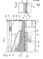
- the fireplace shown in Fig. 1 has a housing 10 and an exhaust pipe 11 coming from its top.
- a filling space designated 12 in the form of a horizontal, elongated cuboid, the longitudinal sides of which essentially extend from one housing wall to the other.
- the filling chamber 12 is accessible from the outside through a filling chamber door 13, indicated in dash-dotted lines and located on the front of the device.
- the bottom 14 of the filling chamber 12 has a grate opening in its one end region, the right end region in the drawing, which is covered by a grate 15. In the area of the grate 15 or in the area above there is a grate door, not shown in the drawing, in the front wall of the housing.
- a closed ash space 16 is provided below the grate, in which an ash box 17 is accommodated.
- the ash chamber 16 also serves as a primary air supply and for this purpose has an opening, which is not shown in the drawing, which leads into the installation space and is adjustable, in a known manner from a thermoelectric or bimetallic temperature sensor arranged in the exhaust gas path, which is shown in the drawing is also not shown.
- the thick wall 18 of the combustion chamber 12 has an exhaust gas passage 19 above the grate 15, which is preferably made of ceramic material.
- the passage 19 opens into an afterburner chamber 20, the walls of which are made of highly heat-resistant material with low thermal conductivity and which has a lateral outlet 21, the upper edge 22 of which is designed as a deflecting edge.
- the outlet 21 of the chamber 20 leads to a heat transfer space 23 with a baffle plate 24, which supplies the exhaust gases to the exhaust pipe 11.
- a baffle plate 24 which supplies the exhaust gases to the exhaust pipe 11.
- transverse bores 25 which are connected to the installation space via a distribution duct 26 and a hiss filling space 12 and heat transfer space 23 and serve as secondary air ducts.
- the grate-side end wall 28 of the filling chamber 12 / which is on the right in the drawing, is covered with heat-resistant material and preferably provided with vertical grooves.
- a slide 29 is accommodated in the filling chamber 12, which has the shape of a plate corresponding to the cross section of the filling chamber 12 and is supported by a spring 30 against the end wall of the filling chamber 12 opposite the end wall 28, that is to say in the drawing of the left end wall.
- the path of movement of the slide 29 essentially extends from a position close to the left end wall (tensioned spring) to a position preferably close to the grate opening.
- the slider 29 is coupled by a - not shown - simple lever mechanism to the filling door 13, such that when the door 13 is opened the slider is returned to its left end position against the force of the spring 30 and held there, when the door 13 is closed is released again.
- the fireplace works as follows.
- the filling chamber door 13 is opened, whereby the slide 29 is brought into its retracted (left) position.
- the fuel such as logs, elongated lignite briquettes, peat briquettes and the like, can be introduced into the filling chamber 12, namely in the longitudinal direction, that is to say in such a way that the longitudinal axis of the elongated fuel material runs parallel to the longitudinal axis of the filling chamber 12.
- the ignition material previously placed on the grate 15 through the grate door mentioned is ignited.
- the filling chamber door 13 is closed, with the result that the slide 29 is released and, due to the action of the spring 30, presses the fuel to the right over the grate 15 against the end wall 28.
- the fuel is now burned off with the aid of the primary air supplied from the ash chamber 16 through the grate 15, the primary air / exhaust gas flow which is forced between the grate 15 and the exhaust passage 19 only permitting combustion directly in front of the side wall 28 adjacent to the grate 15.
- An about beginning Expansion of the combustion reaction of the fuel in the direction of the filling chamber 12 (to the left in the drawing) is prevented by the above-mentioned firing controller regulating the quantity of primary air supplied via the exhaust gas temperature thereby increasing, so that an increase in the quantity of fuel in reaction is prevented.
- the exhaust gas passage 19 arranged directly above the firing grate 15 fulfills a double function.
- the exhaust gases After passing through the passage 19, the exhaust gases enter the afterburning chamber 20, in which they are deflected by 90 ° and are partially forced to recirculate via the deflection edge 22.
- the process in the afterburning chamber can additionally be supported by a tangential and obliquely upstream arrangement of the secondary air channels 25 in the passage 19. After leaving the afterburning chamber 20, the exhaust gases then enter the heat transfer space 23 and flow around the baffle plate 24 to the exhaust port 11.
- FIG. 2 and 2a show a second embodiment of the invention, this fireplace being intended in particular for lumpy fuel, such as gas-rich lump coal.
- This embodiment differs from that of FIG. 1 only with regard to the delivery device for the fuel.
- a plurality of conveyor fingers 31 are provided here, which grow out in a prong-like manner from a conveyor fork 32, which is articulated on both sides on the circumference of two drive wheels.
- the two drive wheels are connected by a shaft 34 b, which runs transversely to the fuel delivery direction (FIG. 2A).
- a plurality of such conveying units are arranged one behind the other below the bottom 14 of the filling chamber 12 with openings, 33 transmission wheels 34 being interposed in each case between the drive wheels.
- the tines 31 of the conveying forks 32 pass through the openings of the base 14 into the filling space 12.
- One of the transmission wheels 34 is connected to a main drive wheel 35 which is rotated by a drive 36, the drive 36 being a manual drive, about a hand crank, or a mechanical drive, for example an electric motor. If the drive 36 rotates the main drive wheel 35 in the direction of rotation shown in FIG. 2, this drives the conveying device, ie the tines 31 pivot in the conveying direction (to the right in FIG. 2) and then convey the fuel towards the grate 15, whereupon the tines 31 pulled down are carried out, a pivoting in the opposite direction and then penetrate again into the filling chamber 12, in the pivoting position shown in Fig. 2.
- the spring 30 ensures that the fuel is fed in accordance with the erosion
- the drive 36 is an electric motor
- an automatic control of the feed can be achieved either by touching contacts on the end wall 28 or, which is more expedient via the existing or an additional exhaust gas temperature sensor. It is also possible to provide a program control in the case of a motor drive 36, which controls the combustion (primary air supply) and the fuel delivery as a function of time.
- adjustable layer height regulator 37 is provided in the form of a sheet articulated on one side.
- Fig. 3 shows an enlarged individual view of the exhaust passage 19 in horizontal section, as used in the fireplaces according to FIGS. 1 and 2.
- air heated by the supply duct 27 is supplied in the direction of the arrow to the distributor duct 26, from which it enters the exhaust gas passage through the secondary air ducts 25.
- a tangential and obliquely downstream arrangement of the channels 25 supports the post-combustion process; this particular arrangement of the channels 25 is shown in 3 illustrates.
- the firing grate 15 it is advantageous to design the firing grate 15 as divided.
- Two possible designs of such a grating division are shown in FIGS. 4 and 5. 4, the one grate part 15a is pivotable, the other grate part 15b is arranged rigidly, while in FIG. 5 both grate parts 15a and 15b are pivotable.
- the grate trough and the free passage cross-section for the primary air can be easily adjusted in a fuel-specific manner during operation without there being a risk that the fuel will become stuck to the grate and the combustion will be interrupted.
- the burning rate can be changed directly by changing the grate passage cross-section, preferably automatically by means of a sensor system, which uses the exhaust gas temperature to adjust the output by adjusting the free space, instead of the aforementioned conventional firing controller for the primary air Grate cross section and the grate tray regulates.
- This type of output control is superior to the primary air control with an unchangeable free grate cross-section (the air access to the space below the grate is regulated) in hygienic and economic terms, because the rust-related reaction surface is adapted to the fuel and not only the primary air is adjusted with the grate surface and ember layer height remaining the same .
Landscapes
- Engineering & Computer Science (AREA)
- Chemical & Material Sciences (AREA)
- Combustion & Propulsion (AREA)
- Mechanical Engineering (AREA)
- General Engineering & Computer Science (AREA)
- Solid-Fuel Combustion (AREA)
Priority Applications (2)
| Application Number | Priority Date | Filing Date | Title |
|---|---|---|---|
| EP84110142A EP0175794A1 (fr) | 1984-08-24 | 1984-08-24 | Foyer individuel pour combustibles solides |
| ES545972A ES8608658A1 (es) | 1984-08-24 | 1985-08-07 | Perfeccionamientos en los hogares de combustion individual para los combustibles solidos |
Applications Claiming Priority (1)
| Application Number | Priority Date | Filing Date | Title |
|---|---|---|---|
| EP84110142A EP0175794A1 (fr) | 1984-08-24 | 1984-08-24 | Foyer individuel pour combustibles solides |
Publications (1)
| Publication Number | Publication Date |
|---|---|
| EP0175794A1 true EP0175794A1 (fr) | 1986-04-02 |
Family
ID=8192129
Family Applications (1)
| Application Number | Title | Priority Date | Filing Date |
|---|---|---|---|
| EP84110142A Withdrawn EP0175794A1 (fr) | 1984-08-24 | 1984-08-24 | Foyer individuel pour combustibles solides |
Country Status (2)
| Country | Link |
|---|---|
| EP (1) | EP0175794A1 (fr) |
| ES (1) | ES8608658A1 (fr) |
Cited By (2)
| Publication number | Priority date | Publication date | Assignee | Title |
|---|---|---|---|---|
| EP2228603A3 (fr) * | 2009-03-12 | 2013-12-11 | Global Mind Network GmbH | Procédé de réglage de la puissance d'un four à carburant solide et four doté d'un réglage de la puissance correspondant |
| AT527552A1 (de) * | 2023-08-28 | 2025-03-15 | Eta Heiztechnik Gmbh | Heizkessel |
Citations (5)
| Publication number | Priority date | Publication date | Assignee | Title |
|---|---|---|---|---|
| DE229208C (fr) * | ||||
| DE627974C (de) * | 1933-12-03 | 1936-03-27 | Hermann Ernst Zierenberg | Vorrichtung zur Regelung der Groesse des Feuerraumes bei Kochherden, Heizoefen o. dgl. |
| US2078640A (en) * | 1934-08-09 | 1937-04-27 | Leonard H Segar | Automatic coal stoking device |
| US4343288A (en) * | 1977-06-17 | 1982-08-10 | Tjosvold David C | Furnace |
| EP0087878A1 (fr) * | 1982-02-22 | 1983-09-07 | Corning Glass Works | Poêle à bois |
-
1984
- 1984-08-24 EP EP84110142A patent/EP0175794A1/fr not_active Withdrawn
-
1985
- 1985-08-07 ES ES545972A patent/ES8608658A1/es not_active Expired
Patent Citations (5)
| Publication number | Priority date | Publication date | Assignee | Title |
|---|---|---|---|---|
| DE229208C (fr) * | ||||
| DE627974C (de) * | 1933-12-03 | 1936-03-27 | Hermann Ernst Zierenberg | Vorrichtung zur Regelung der Groesse des Feuerraumes bei Kochherden, Heizoefen o. dgl. |
| US2078640A (en) * | 1934-08-09 | 1937-04-27 | Leonard H Segar | Automatic coal stoking device |
| US4343288A (en) * | 1977-06-17 | 1982-08-10 | Tjosvold David C | Furnace |
| EP0087878A1 (fr) * | 1982-02-22 | 1983-09-07 | Corning Glass Works | Poêle à bois |
Cited By (2)
| Publication number | Priority date | Publication date | Assignee | Title |
|---|---|---|---|---|
| EP2228603A3 (fr) * | 2009-03-12 | 2013-12-11 | Global Mind Network GmbH | Procédé de réglage de la puissance d'un four à carburant solide et four doté d'un réglage de la puissance correspondant |
| AT527552A1 (de) * | 2023-08-28 | 2025-03-15 | Eta Heiztechnik Gmbh | Heizkessel |
Also Published As
| Publication number | Publication date |
|---|---|
| ES545972A0 (es) | 1986-07-16 |
| ES8608658A1 (es) | 1986-07-16 |
Similar Documents
| Publication | Publication Date | Title |
|---|---|---|
| EP0193632B1 (fr) | Procédé pour la combustion contrôlée d'une pile en combustible solide notamment en bois entassé dans une cheminée verticale de chauffage d'un poêle ainsi que poêle pour la mise en oeuvre du procédé | |
| DE2820933A1 (de) | Feuerungsanlage fuer festes brennmaterial | |
| AT398826B (de) | Heizanlage zum verbrennen von festen brennstoffen | |
| EP0038962A1 (fr) | Dispositif pour la combustion de matières solides légères par un foyer à chargement continu | |
| EP0409790A1 (fr) | Installation de combustion | |
| AT505521B1 (de) | Vorrichtung zum verbrennen von festbrennstoffelementen | |
| DE3614998C2 (fr) | ||
| EP0175794A1 (fr) | Foyer individuel pour combustibles solides | |
| DE3705153C2 (fr) | ||
| DE3345963C2 (de) | Feuerstätte für feste Brennstoffe | |
| EP2551591A2 (fr) | Commande de l'air d'alimentation pour un dispositif de chauffage | |
| DE1921881C3 (de) | Rostfeuerung | |
| EP2775201A2 (fr) | Appareil de chauffage, insert de stockage pour un appareil de chauffage et procédé de fonctionnement d'un appareil de chauffage | |
| DE3302348A1 (de) | Feuerstelle | |
| DE3927803C2 (de) | Heizvorrichtung für feste Brennstoffe, insbesondere Kachelofeneinsatz | |
| DE4009316C2 (de) | Heizvorrichtung für feste Brennstoffe | |
| AT3840U1 (de) | Verfahren zum verbrennen und vergasen von festen biomassen in einem brennraum | |
| DE3902091A1 (de) | Kachelofen-heizeinsatz | |
| DE1954535C3 (de) | Schachtofen mit Luftzufuhröffnungen aufweisendem Rost | |
| DE3125163C2 (fr) | ||
| DE653944C (de) | Kaminfeuerung zum wahlweisen oder gleichzeitigen Betrieb mit festem Brennstoff oder mit Gas | |
| DE952127C (de) | Dauerbrandofen | |
| DE8405921U1 (de) | Vorgefertigte feuerstaette fuer feste brennstoffe | |
| DE3315199A1 (de) | Festbrennstoffvergasungsanlage | |
| DE20116362U1 (de) | Heizkessel für festen Brennstoff, insbesondere Pellets |
Legal Events
| Date | Code | Title | Description |
|---|---|---|---|
| PUAI | Public reference made under article 153(3) epc to a published international application that has entered the european phase |
Free format text: ORIGINAL CODE: 0009012 |
|
| AK | Designated contracting states |
Kind code of ref document: A1 Designated state(s): AT CH DE FR GB IT LI SE |
|
| 17P | Request for examination filed |
Effective date: 19860610 |
|
| 17Q | First examination report despatched |
Effective date: 19861029 |
|
| STAA | Information on the status of an ep patent application or granted ep patent |
Free format text: STATUS: THE APPLICATION HAS BEEN WITHDRAWN |
|
| 18W | Application withdrawn |
Withdrawal date: 19870306 |
|
| RIN1 | Information on inventor provided before grant (corrected) |
Inventor name: SCHMIDT, H. LOTHAR, DIPL. ING. |