EP0175800A1 - Tête de transducteur magnétique - Google Patents
Tête de transducteur magnétique Download PDFInfo
- Publication number
- EP0175800A1 EP0175800A1 EP84111377A EP84111377A EP0175800A1 EP 0175800 A1 EP0175800 A1 EP 0175800A1 EP 84111377 A EP84111377 A EP 84111377A EP 84111377 A EP84111377 A EP 84111377A EP 0175800 A1 EP0175800 A1 EP 0175800A1
- Authority
- EP
- European Patent Office
- Prior art keywords
- magnetic
- recording
- recording medium
- erasing
- pole
- Prior art date
- Legal status (The legal status is an assumption and is not a legal conclusion. Google has not performed a legal analysis and makes no representation as to the accuracy of the status listed.)
- Withdrawn
Links
Images


Classifications
-
- G—PHYSICS
- G11—INFORMATION STORAGE
- G11B—INFORMATION STORAGE BASED ON RELATIVE MOVEMENT BETWEEN RECORD CARRIER AND TRANSDUCER
- G11B5/00—Recording by magnetisation or demagnetisation of a record carrier; Reproducing by magnetic means; Record carriers therefor
- G11B5/127—Structure or manufacture of heads, e.g. inductive
- G11B5/1278—Structure or manufacture of heads, e.g. inductive specially adapted for magnetisations perpendicular to the surface of the record carrier
-
- G—PHYSICS
- G11—INFORMATION STORAGE
- G11B—INFORMATION STORAGE BASED ON RELATIVE MOVEMENT BETWEEN RECORD CARRIER AND TRANSDUCER
- G11B5/00—Recording by magnetisation or demagnetisation of a record carrier; Reproducing by magnetic means; Record carriers therefor
- G11B5/10—Structure or manufacture of housings or shields for heads
- G11B5/11—Shielding of head against electric or magnetic fields
-
- G—PHYSICS
- G11—INFORMATION STORAGE
- G11B—INFORMATION STORAGE BASED ON RELATIVE MOVEMENT BETWEEN RECORD CARRIER AND TRANSDUCER
- G11B5/00—Recording by magnetisation or demagnetisation of a record carrier; Reproducing by magnetic means; Record carriers therefor
- G11B5/127—Structure or manufacture of heads, e.g. inductive
- G11B5/265—Structure or manufacture of a head with more than one gap for erasing, recording or reproducing on the same track
- G11B5/2652—Structure or manufacture of a head with more than one gap for erasing, recording or reproducing on the same track with more than one gap simultaneously operative
- G11B5/2654—Structure or manufacture of a head with more than one gap for erasing, recording or reproducing on the same track with more than one gap simultaneously operative for recording or erasing
- G11B5/2655—Structure or manufacture of a head with more than one gap for erasing, recording or reproducing on the same track with more than one gap simultaneously operative for recording or erasing with all the gaps disposed within the track or "guard band" between tracks, e.g. with erase gaps operative on track edges, with wide erase gap followed by narrow write gap
Definitions
- the present invention relates to a signal pole type combination magnetic transducer head for perpendicular mode recording, which is suitably applied to a recording and/or reproducing head of a flexible disc device to use, for example, a flexible disc as a magnetic recording medium.
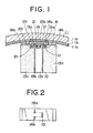
- FIGs. 1 and 2 A single pole type combination magnetic transducer head for perpendicular mode recording as shown in Figs. 1 and 2, which is suitably applied to a recording and/or reproducing head of a flexible disc device to use, for example, a flexible disc as a magnetic recording medium has been already proposed in international patent application No. PCT/JP84/00110 of the assignee of the present invention.
- numeral 10 designates a main magnetic pole for recording and/or reproducing signal, formed of a thin film of soft magnetic material and having one end of a predetermined width facing to a magnetic recording medium 11.
- the recording and/or reproducing main magnetic pole 10 is grasped at the end facing to the magnetic recording medium 11 by non-magnetic guard members 12a and 12b of a predetermined thickness integrally from both sides, and a magnetic core 13a and a non-magnetic body 13b abut on rear side of the non-magnetic guard members 12a and 12b and grasp the recording and/or reproducing main magnetic pole 10 integrally from both sides.
- the magnetic core 13a installed at rear side of the non-magnetic guard member 12a constitutes a return path for magnetic flux of the recording and/or reproducing main magnetic pole 10.
- the magnetic core 13a is provided near the recording and/or reproducing main magnetic pole 10 at side abutting on the non-magnetic guard member 12a with a groove 15 so as to separate an auxiliary magnetic pole 14a near the recording and/or reproducing main magnetic pole 10 from a return path part 14b to constitute a return path for magnetic flux of the main magnetic pole 10. Also the non-magnetic body 13b is provided at side abutting on the non-magnetic guard member 12b with a predetermined groove 16, and through these grooves 15, 16 a recording and/or reproducing winding 17 is applied to the recording and/or reproducing main magnetic pole 10.
- the magnetic recording medium 11 used in this case is composed of, for example, a plastic base lla, a layer llb of material having high permeability formed on the base lla, and a perpendicular mode recording layer llc formed on the layer llb.
- Numerals 18a and 18b designate tunnel erasing main magnetic poles, each formed of a thin film of soft magnetic material and disposed at downstream side of the recording and/or reproducing main magnetic pole 10, and the tunnel erasing magnetic poles 18a and 18b are arranged with each other at distance less than width of the recording and/or reproducing main magnetic pole 10.
- the tunnel erasing main magnetic poles 18a, 18b arranged at the distance less than the width of the recording and/or reproducing main magnetic pole 10 are on the abutting surface of the non-magnetic guard member 12b and the non-magnetic body 13b at opposite side to surface where the recording and/or reproducing main magnetic pole 10 is grasped, so that the tunnel erasing main magnetic poles 18a, 18b are grasped from both sides by the non-magnetic guard member 12b, the non-magnetic body 13b, and a non-magnetic guard member 12c and a magnetic core 13c abutted on rear side of the guard member 12c.
- the magnetic core 13c constitutes a return path for magnetic flux of the tunnel erasing main magnetic poles 18a, 18b.
- the magnetic core 13c is provided near the tunnel erasing main electrodes 18a, 18b at-side abutting on the non-magnetic guard member 12c with a groove 20 so as to separate an auxiliary magnetic pole 19a near the tunnel erasing main magnetic poles 18a, 18b from a return path part 19b to constitute a return path for magnetic flux of the main magnetic poles 18a, 18b.
- An erasing winding 21 is applied to the tunnel erasing main electrodes 18a, 18b through the groove 20 and the groove 16 of the non-magnetic body 13b.
- non-magnetic block substances 22 and 23 are prepared as shown in Fig. 3A.
- the non-magnetic block substances 22 and 23 are preferably made of material being fine-grained, similar to ferrite in thermal expansion coefficient and hard, for example, non-magnetic ferrite (Zn ferrite, forsterite, fotoceram, crystallized glass, barium titanate, calcium titanate, ceramics of Al 2 O 3 -TiC series, Zro 2 or the like).
- Grooves 24 to be made winding holes 16 later are formed at predetermined intervals on one non-magnetic block substance 22 ( F ig. 3B), and then the grooved surfaces are ground in mirror finish. Other non-magnetic block substance 23 is also ground in mirror finish. Both non-magnetic block substances are adhered to each other by means of glass fusion, an organic adhesive agent such as epoxy resin, an inorganic adhesive agent such as water glass or the like (Fig. 3C). Intermediate portions between the grooves 24 are cut in parallel to the grooves 24 and the cutting surfaces are ground in mirror finish. In this case, the core thickness (W 1 , W 2 ) on position of the winding hole 16 is important because it defines the winding diameter.
- the core is preferably as thin as possible. Consequently, the core may be made thin as long as it is allowable in the mechanical strength and the machining workability.
- the core thickness may be 100 m or less, preferably 50 m or less. Since the sensitivity is particularly required at the recording and/or reproducing winding side, the core should be made thin. Since the sensitivity is not so required at the tunnel erasing side as at the recording and/or reproducing side, the core may be made thin at the recording and/or reproducing side and thick at the tunnel erasing side so as to hold the intensity as a whole.
- the grinding surface and a lateral surface front side in Fig.
- a recording and/or reproducing main magnetic pole 10 and tunnel erasing main magnetic poles 18a, 18b are formed on the surface in mirror finish as shown in Fig. 3E.
- a film of Si0 2 , Si 3 N 4 , Al 2 O 3 , Zro 2 or the like is applied to both grinding surfaces at thickness of about 0.1 - 1.0 m by means of sputtering, evaporation, ion plating or the like.
- Condition to apply the film as fine-grained as possible is preferable.
- the film need not always be applied, but magnetic characteristics of a magnetic thin film on the film can be improved as effect by applying the film.
- To one surface If W 1 and W 2 are not equal in Fig. 3D and Fig. 4, surface at smaller side, i.e.
- a magnetic thin film (magnetic film of high permeability such as permalloy, sendust alloy or amorphous magnetic alloy of Co - Zr or Co - Zr - Nb) to be made the recording and/or reproducing film at thickness of about 0.05 m -3 m by means of sputtering, evaporation, ion plating, metal plating or the like.
- the thickness is determined in consideration of necessary resolution and recording and/or reproducing sensitivity. Thickness of about 0.1 m - 0.5 m is practicable.
- the magnetic film is formed in stripe of predetermined track width and distance using photo lithography technique.
- the stripe is located at a predetermined position from the reference end for the alignment with the tunnel erasing main magnetic poles 18a, 18b to be installed later.
- the magnetic film need not be formed in stripe but may be widened at rear side from the abutting portion as shown in Fig. 5. this constitution provides the high sensitivity.
- a hard film of Si0 2 , Si 3 N 4 , A1 2 0 3 as a protective film is applied at thickness of about 0.1 m -3 m onto the magnetic film by means of sputtering, evaporation, ion plating or the like.
- a magnetic thin film such as permalloy, sendust alloy, or amorphous magnetic alloy of Co - Zr or Co - Zr - N b to be made a tunnel erasing main magnetic pole is applied at thickness of about 0.1 - 5 m onto the surface at opposite side by means of sputtering, evaporation, ion plating, metal plating or the like.
- the thickness is set to provide the best erasing sensitivity, but in most cases the thickness of about 0.5 - 1 m is suitable.
- etching is performed at a predetermined width corresponding to the recording and/or reproducing magnetic film onto a pair of magnetic films in stripe.
- a hard film of SiO 2 , Si 3 N 4 or A1 2 O 3 as a protective film is applied at thickness of about 0.1 m - 3 m onto the magnetic film by means of sputtering, evaporation, ion plating or the like.
- the tunnel erasing magnetic film may be formed in configuration as shown in Fig. 6.
- Fig. 7 shows relation of mutual position between the recording and/or reproducing main magnetic pole 10 and the tunnel erasing main magnetic poles 18a, 18b.
- Width T 1 of the recording and/or reproducing main magnetic pole 10 is larger than distance TO between the tunnel erasing main magnetic poles 18a, 18b. Since recording is performed at the recording and/or reproducing main magnetic pole 10 and then the end of the recording is erased at the tunnel erasing main magnetic poles 18a, 18b, the track width to be finally recorded becomes equal to the distance TO between the tunnel erasing main magnetic poles 18a, 18b and the recording and/or reproducing main magnetic pole 10 and the tunnel erasing main magnetic poles 18a, 18b must be aligned at high precision.
- the recording and/or reproducing main magnetic pole 10 is first aligned from the end of the substrate at high precision and then the tunnel erasing main magnetic poles 18a, 18b are aligned from the end as reference point. Therefore the lateral surface as reference plane must be perpendicular and have the sharp edge as already described.
- a transparent substrate is used (Either one transparent substrate will do because of the abutting.) and when second patterning of the magnetic pole is performed the pattern position may be confirmed from the rear side.
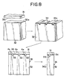
- a composite block shown in F ig. 3F is prepared.
- the composite block is fabricated as shown in Fig. 8.
- a non-magnetic plate block 31 and a magnetic block 32 are first prepared.
- the non-magnetic plate block 31 may be made of non-magnetic ferrite (Zn ferrite), fersterite, fotoceram, crystallized glass, barium titanate, calcium titanate or ceramics of A1 2 0 3 - TiC series
- the magnetic block 32 may be made of ferrite of Mn - Zn series or N i - Zn series.
- the non-magnetic block 31 and the magnetic block 32 are preferably made of non-magnetic ferrite and magnetic ferrite, respectively.
- Each one surface of the non-magnetic plate block 31 and the magnetic block 32 is ground in mirror finish. Grooves 33 are formed at predetermined, intervals on the mirror finish surface 32a of the magnetic block 32. In this state, the mirror finish surface 31a of the non-magnetic plate block 31 is faced and adhered to the mirror finish surface 32a of the magnetic block 32.
- the adhesion may e performed by means of glass fusion or an adhesive agent 34 such as epoxy adhesive agent, an inorganic adhesive agent such as water glass.
- the above-mentioned single pole type combination magnetic transducer head for perpendicular mode recording is used for example in a recording and/or reproducing head of a flexible disc device and recording is performed on the magnetic recording medium, recording signal is supplied to a recording and/or reproducing winding 17 of the recording main magnetic pole 10 and perpendicular mode magnetic recording is performed by the recording and/or reproducing main magnetic pole 10 and erasing current (DC) is supplied to an erasing winding 21 of the tunnel erasing main magnetic poles 18a, 18b thereby both sides of the recording track are erased.
- DC erasing current
- a magnetic transducer head of the present invention comprises a first magnetic pole for recording and/or reproducing signal on a travelling magnetic recording medium, formed of a thin film of magnetic material facing to the travelling magnetic recording medium at one end of the thin film and having a predetermined width corresponding to a recording track width on the magnetic recording medium; a coil coupled to the first magnetic pole for recording and/or reproducing signal on the travelling magnetic recording medium; second and third magnetic poles for erasing magnetic record at peripheral portions of the recording track formed of thin films of magnetic material each facing to the travelling magnetic recording medium at one end of the thin film, the second and third magnetic poles provided remote from the first magnetic pole with a predetermined distance along a travelling direction of the magnetic recording medium; a coil coupled to the second and third magnetic poles for erasing magnetic record; and a coil coupled to the first magnetic pole to compensate an erasing magnetic field from the second and third magnetic poles in the first magnetic pole.
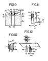
- FIG. 9 A single pole type combination magnetic transducer head for perpendicular mode recording as an embodiment of the invention will now be described referring to Fig. 9.
- parts corresponding to Fig. 1 are designated by the same reference numerals and detailed description thereof shall be omitted.
- an erasing winding 21 is applied to tunnel erasing main magnetic poles 18a, 18b, and a wire in extension of the erasing winding 21 is wound as a compensating winding 40 to a recording and/or reproducing main magnetic pole 10 as shown in Fig. 10 thereby erasing current is supplied in similar manner to Fig. 1.
- the compensating winding 40 is set to the winding direction and the winding number so that leakage flux from the tunnel erasing main magnetic poles 18a, 18b is canceled.
- This embodiment has similar constitution to that of Fig. 1 except for above description.
- the compensating winding 40 applied to the recording and/or reproducing main magnetic pole 10 may be connected in parallel to the erasing winding 21 as shown in F ig. 11.
- the erasing winding 21 and the compensating winding 40 are connected at each one end to a resistor 41 and a variable resistor 42 respectively, and commonly connected at each other end to collector of npn transistor 44.
- Emitter of the transistor 44 is earthed, and control signal is supplied to an input terminal 45 led from base of the transistor 44 so that the transistor 44 is turned ON at the recording state.
- resistance value of the variable resistor 42 is adjusted irrespective of the winding number of the compensating winding 40, thereby leakage flux from the tunnel erasing main magnetic poles 18a, 18b can be canceled well. Consequently, this constitution is advantageous in the viewpoint of designing and manufacturing.
- Fig. 12 shows another embodiment of the invention.
- auxiliary magnetic pole energizing type In order to energize the main magnetic pole 10 as magnetic transducer head for perpendicular mode recording, auxiliary magnetic pole energizing type has been previously proposed where an auxiliary magnetic pole 46 with a recording and/or reproducing winding 17 applied thereto is installed to the main magnetic pole 10 through a magnetic recording medium 11 interposed between the main magnetic pole 10 and the auxiliary magnetic pole 46.
- Fig. 12 discloses application of the invention to the auxiliary magnetic pole energizing type.
- the compensating winding 40 is provided on the auxiliary magnetic pole 46, and suitable current to cancel the leakage flux from the tunnel erasing main magnetic poles 18a, 18b is supplied to the compensating winding 40. It is clearly understood that constitution in Fig. 12 has working effect similar to Fig. 9.
- influence of the leakage flux from the tunnel erasing main magnetic poles 18a, 18b to the recording signal can be eliminated.
Landscapes
- Engineering & Computer Science (AREA)
- Manufacturing & Machinery (AREA)
- Magnetic Heads (AREA)
Priority Applications (1)
| Application Number | Priority Date | Filing Date | Title |
|---|---|---|---|
| EP84111377A EP0175800A1 (fr) | 1984-09-24 | 1984-09-24 | Tête de transducteur magnétique |
Applications Claiming Priority (1)
| Application Number | Priority Date | Filing Date | Title |
|---|---|---|---|
| EP84111377A EP0175800A1 (fr) | 1984-09-24 | 1984-09-24 | Tête de transducteur magnétique |
Publications (1)
| Publication Number | Publication Date |
|---|---|
| EP0175800A1 true EP0175800A1 (fr) | 1986-04-02 |
Family
ID=8192173
Family Applications (1)
| Application Number | Title | Priority Date | Filing Date |
|---|---|---|---|
| EP84111377A Withdrawn EP0175800A1 (fr) | 1984-09-24 | 1984-09-24 | Tête de transducteur magnétique |
Country Status (1)
| Country | Link |
|---|---|
| EP (1) | EP0175800A1 (fr) |
Cited By (3)
| Publication number | Priority date | Publication date | Assignee | Title |
|---|---|---|---|---|
| EP0258534A1 (fr) * | 1986-09-04 | 1988-03-09 | GRUNDIG E.M.V. Elektro-Mechanische Versuchsanstalt Max Grundig holländ. Stiftung & Co. KG. | Tête magnétique avec tête d'effacement contigüe |
| US4787002A (en) * | 1984-04-12 | 1988-11-22 | Mitsubishi Denki Kabushiki Kaisha | Magnetic head having a read/write coil with a d.c. current through it for cancellation of leakage magnetic flux from erase coil |
| EP0456316A3 (en) * | 1990-05-08 | 1992-09-02 | Laser Magnetic Storage International Company | Compatible magnetic head assembly |
Citations (3)
| Publication number | Priority date | Publication date | Assignee | Title |
|---|---|---|---|---|
| EP0039090A2 (fr) * | 1980-04-30 | 1981-11-04 | Kabushiki Kaisha Toshiba | Structure de tête magnétique et procédé pour sa fabrication |
| EP0099831A1 (fr) * | 1982-07-20 | 1984-02-01 | Vertimag Systems Corporation | Tête magnétique pour médium d'enregistrement perpendiculaire |
| JPS59124016A (ja) * | 1982-12-29 | 1984-07-18 | Sony Corp | 磁気ヘツド |
-
1984
- 1984-09-24 EP EP84111377A patent/EP0175800A1/fr not_active Withdrawn
Patent Citations (3)
| Publication number | Priority date | Publication date | Assignee | Title |
|---|---|---|---|---|
| EP0039090A2 (fr) * | 1980-04-30 | 1981-11-04 | Kabushiki Kaisha Toshiba | Structure de tête magnétique et procédé pour sa fabrication |
| EP0099831A1 (fr) * | 1982-07-20 | 1984-02-01 | Vertimag Systems Corporation | Tête magnétique pour médium d'enregistrement perpendiculaire |
| JPS59124016A (ja) * | 1982-12-29 | 1984-07-18 | Sony Corp | 磁気ヘツド |
Non-Patent Citations (4)
| Title |
|---|
| PATENTS ABSTRACTS OF JAPAN, vol. 6, no. 175 (P-141)[1053], 9th September 1982; & JP-A-57 092416 (SUWA SEIKOSHA K.K.) 09-06-1982 * |
| PATENTS ABSTRACTS OF JAPAN, vol. 6, no. 183 (P-143)[1061], 18th September 1982; & JP-A-57 098124 (TOKYO SHIBAURA DENKI K.K.) 18-06-1982 * |
| PATENTS ABSTRACTS OF JAPAN, vol. 8, no. 245 (P-312)[1682], 10th November 1984; & JP-A-59 117 727 (NIPPON DENKI K.K.) 07-07-1984 * |
| PATENTS ABSTRACTS OF JAPAN, vol. 9, no. 37 (P-335)[1760], 16th February 1985; & JP-A-59 177 714 (SONY K.K.) 08-10-1984 * |
Cited By (3)
| Publication number | Priority date | Publication date | Assignee | Title |
|---|---|---|---|---|
| US4787002A (en) * | 1984-04-12 | 1988-11-22 | Mitsubishi Denki Kabushiki Kaisha | Magnetic head having a read/write coil with a d.c. current through it for cancellation of leakage magnetic flux from erase coil |
| EP0258534A1 (fr) * | 1986-09-04 | 1988-03-09 | GRUNDIG E.M.V. Elektro-Mechanische Versuchsanstalt Max Grundig holländ. Stiftung & Co. KG. | Tête magnétique avec tête d'effacement contigüe |
| EP0456316A3 (en) * | 1990-05-08 | 1992-09-02 | Laser Magnetic Storage International Company | Compatible magnetic head assembly |
Similar Documents
| Publication | Publication Date | Title |
|---|---|---|
| EP0521564B1 (fr) | Tête magnétique à films minces | |
| US5095397A (en) | Thin film magnetic head of embodied recording and reproducing transducer type | |
| EP0411914A2 (fr) | Tête magnétique en films minces | |
| JPS6341127B2 (fr) | ||
| CA1204508A (fr) | Tete de transducteur magnetique | |
| US4924334A (en) | Magnetic storage device with track guidance system | |
| EP0139018B1 (fr) | Assemblage de têtes transductrices magnétiques d'un seul type de pôles magnétiques pour enregistrement perpendiculaire | |
| EP0175800A1 (fr) | Tête de transducteur magnétique | |
| US4768121A (en) | Magnetic head formed by composite main pole film and winding core for perpendicular magnetic recording | |
| KR900004743B1 (ko) | 수직 자기기록용 자기헤드 및 그 제조방법 | |
| US4939609A (en) | Vertical recording head with thin film pole on non-magnetic block | |
| JP2505465B2 (ja) | ヨ−ク型薄膜磁気ヘッド | |
| EP0602486B1 (fr) | Tête magnétique flottante | |
| JPH0232682B2 (ja) | Jikihetsudo | |
| JPS59177714A (ja) | 垂直記録用単磁極型複合磁気ヘツド | |
| JPS6222219A (ja) | 薄膜磁気ヘツド | |
| JPS6173220A (ja) | 磁気抵抗型ヘツド | |
| KR940004485B1 (ko) | 복합형 자기헤드와 그 제조방법 | |
| EP0137049A1 (fr) | Tete d'enregistrement magnetique perpendiculaire | |
| JPS60154317A (ja) | ストラドルイレ−ズ型磁気ヘツドの製造方法 | |
| JPS59191119A (ja) | 垂直記録用単磁極型複合磁気ヘツド | |
| JPS6226618A (ja) | 薄膜磁気ヘツド | |
| JPS59175013A (ja) | 垂直記録用単磁極型複合磁気ヘツド | |
| JPS6216209A (ja) | 単磁極型磁気ヘツド | |
| JPS60205813A (ja) | 垂直磁気記録再生用の薄膜磁気ヘツド |
Legal Events
| Date | Code | Title | Description |
|---|---|---|---|
| PUAI | Public reference made under article 153(3) epc to a published international application that has entered the european phase |
Free format text: ORIGINAL CODE: 0009012 |
|
| AK | Designated contracting states |
Kind code of ref document: A1 Designated state(s): DE FR GB NL |
|
| 17P | Request for examination filed |
Effective date: 19860707 |
|
| 17Q | First examination report despatched |
Effective date: 19880129 |
|
| STAA | Information on the status of an ep patent application or granted ep patent |
Free format text: STATUS: THE APPLICATION IS DEEMED TO BE WITHDRAWN |
|
| 18D | Application deemed to be withdrawn |
Effective date: 19880609 |
|
| RIN1 | Information on inventor provided before grant (corrected) |
Inventor name: KYONORI, HAYAKAWA |