EP0175951B1 - Dispositif pour saisir et manipuler des articles - Google Patents
Dispositif pour saisir et manipuler des articles Download PDFInfo
- Publication number
- EP0175951B1 EP0175951B1 EP19850110797 EP85110797A EP0175951B1 EP 0175951 B1 EP0175951 B1 EP 0175951B1 EP 19850110797 EP19850110797 EP 19850110797 EP 85110797 A EP85110797 A EP 85110797A EP 0175951 B1 EP0175951 B1 EP 0175951B1
- Authority
- EP
- European Patent Office
- Prior art keywords
- blade parts
- blade
- gripping members
- grip
- parts
- Prior art date
- Legal status (The legal status is an assumption and is not a legal conclusion. Google has not performed a legal analysis and makes no representation as to the accuracy of the status listed.)
- Expired
Links
- 239000000463 material Substances 0.000 claims description 16
- 235000013351 cheese Nutrition 0.000 claims description 3
- 230000007704 transition Effects 0.000 claims description 2
- 235000013305 food Nutrition 0.000 description 5
- 210000003811 finger Anatomy 0.000 description 3
- 210000003813 thumb Anatomy 0.000 description 2
- 230000005489 elastic deformation Effects 0.000 description 1
- 230000005389 magnetism Effects 0.000 description 1
- 239000002184 metal Substances 0.000 description 1
- 238000000034 method Methods 0.000 description 1
- 238000004080 punching Methods 0.000 description 1
Images

Classifications
-
- A—HUMAN NECESSITIES
- A47—FURNITURE; DOMESTIC ARTICLES OR APPLIANCES; COFFEE MILLS; SPICE MILLS; SUCTION CLEANERS IN GENERAL
- A47G—HOUSEHOLD OR TABLE EQUIPMENT
- A47G21/00—Table-ware
- A47G21/04—Spoons; Pastry servers
- A47G21/045—Pastry servers
-
- B—PERFORMING OPERATIONS; TRANSPORTING
- B26—HAND CUTTING TOOLS; CUTTING; SEVERING
- B26B—HAND-HELD CUTTING TOOLS NOT OTHERWISE PROVIDED FOR
- B26B3/00—Hand knives with fixed blades
- B26B3/03—Hand knives with fixed blades specially adapted for cutting-off slices one by one
Definitions
- the invention relates to a device according to the precharacterizing portion of claim 1.
- the cylinder sector shaped articles are in practice constituted of parts of food products.
- the food products in question are cylinder shaped and may for example be constituted of cakes, cheese etc.
- the parts obtain the cylinder sector shape when cut out from the food products since such technique of cutting out in general causes the most rational division of the food products into smaller parts.
- DE-utility model patent 8 019 402 there is disclosed a cutting and grasping device having gripping members formed by eyes. Such a design of the gripping members falls outside the scope of the precharacterizing portion of claim 1 and makes it very difficult to efficiently operate the device for cutting, in particular when stiffer cakes are in question, since the user has to operate the device with one hand, namely with the thumb in one eye and the index finger or middle finger in the other eye. Also this known device will most certainly have to be supplemented with a conventional cake slice for handling low or soft cakes.
- the object of the invention is to reduce the above defined draw backs and to achieve a device with a, as far as possible, universal utility for all kinds of cakes or other food products.
- the device according to the invention can be brought in a position where its both blade parts can function as one single cutting blade at the same time as the gripping members form a single elongated rodlike grip, around which one hand may grasp, the device can on one hand be used in a way similar to a conventional cake slice, and on the other hand for grasping the article in question between the two blade parts.
- the device can on one hand be used in a way similar to a conventional cake slice, and on the other hand for grasping the article in question between the two blade parts.
- the device according to the invention will below be described as especially intended for grasping and handling substantially cylinder sector shaped articles in form of pieces of cake.
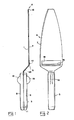
- the device comprises two blade parts 1, 2 and a grip located at one end thereof generally denoted with 3.
- the two blade parts 1 and 2 are pivotally connected to each other by means of a hinge 4 located at that end of the blade parts 1, 2 which is opposite to the grip 3.
- the grip 3 and the hinge 4 are in the exemplified embodiment located at diametrically opposite ends of the device, which here is illustrated as relatively elongated, but which in practice could be substantially shorter and wider.
- the blade parts 1 and 2 are pivotable about the hinge 4 in a direction towards each other to a position (fig. 1) where they lie close to each other or against each other in a substantially parallel condition.
- fig. 1 the intention is that the blade parts 1 and 2 in this position shall form a totally flat and relatively thin disc like structure.
- the blade parts 1 and 2 comprise bends 5 in the vicinity of the grip but these are intended to be located outwardly of the portions of the blade parts 1, 2 which normally come into contact with pieces of cake.
- the hinge 4 is intended to form a geometric pivot axis which extends substantially perpendicularly to the longitudinal direction of the device and parallel with the plane of the blade parts 1, 2.
- Portions 20 which are extending obliquely from the bends 5 in a direction towards the gripping members of the blade parts are located in close vicinity to each other in a parallel condition when the blade parts are pivoted towards each other.
- the blade parts 1, 2 is designed with a cutting edge 7 along at least one edge (see the edge 6 in fig. 2), said cutting edge may possibly be cogged. It is then meant that the cutting edges 7 on the two blade parts 1 and 2 are so designed that the cutting edges cooperate for forming one single main cutting edge, when the two blade parts 1 and 2 are pivoted towards each other.
- the device thus can in a conventional way be used for cutting for instance a piece of cake out of a cake.
- the grip is in the example formed by two gripping members 8, 9, one of which is arranged on the blade part 1 while the other 9 is arranged on the blade part 2.
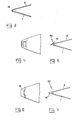
- the gripping members 8 and 9 are each separately operable as a grip when the blade parts 1 and 2 are pivoted away from each other (fig. 8).
- the gripping members 8 and 9 are so designed that they jointly form one single grip 3, which can be grasped by one hand when the blade parts 1, 2 are pivoted towards each other to the position according to fig. 1 and 2.
- the surfaces 10 of the gripping members 8 and 9, which are facing towards each other can in practice be flat to enable a close application against each other analogically to the way in which the blade parts 1 and 2 are applicable against each other.
- the device presents means 11 for holding together the blade parts 1 and 2 in their condition pivoted towards each other.
- Said holding means could be arranged to operate on basis of magnetism.
- the holding means could be designed to operate by mechanical engagement.
- Such mechanical holding means could as an example consist of snap locking means releasable by actuation of a certain force in a direction away from each other or locking means releasable by loosening of a form locking connection. It is suitable to arrange the holding means 11 in the area of the grip 3, preferably so that one means is arranged on each of the gripping members 8 and 9 so that these two means enter into a co-operation holding the gripping members together when they are moved towards each other.
- the blade parts 1 and 2 are lying relatively close to each other in the folded condition according to fig. 1, it is recommendable to design the blade parts 1 and 2 in such a way that they, apart from the area of the hinge 4, not really are deformed during normal use of the device.
- the flat shape of the blade parts 1 and 2 shall thus as far as possible be maintained.
- This material portion 12 should then allow pivoting of the blade parts 1 and 2 towards and away from each other by elastic deformation of the material in the portion 12. It is then preferred that the blade parts 1 and 2 are manufactured in one single material piece and that the flexible material piece 12 forms a transition between the blade parts 1 and 2. The material portion 12 will thereby form a diversion of substantially 180 degrees of the material piece which forms the blade parts 1 and 2. The arrangement can then be such that the elasticity of the material portion 12 tends to actuate the blade parts 1 and 2 to pivot in the direction towards each other to the position according to fig. 1.
- the flexible material portion 12 could instead be arranged to tend to actuate the blade parts 1 and 2 to a position (fig. 3) where they are pivoted away from each other. To obtain the position according to fig. 1 one should thus have to actuate the gripping members 8 and 9 in a direction towards each other by the hand.
- a material piece forming the blade parts 1 and 2 and the material portion 12 may be constituted of metal as well as plastic.
- a hinge 4A has not been formed by a flexible material portion but instead by a portion of the one blade part 1, bent to an eye 14, surrounding a portion of the other blade part 2.
- a hinge 4A has not been formed by a flexible material portion but instead by a portion of the one blade part 1, bent to an eye 14, surrounding a portion of the other blade part 2.
- an arrangement of one or several spring means in a way known per se is required.
- the hinge 4B has been formed by means of a piece 15, which connects the blade parts 1 and 2 in that the piece 15 is pivotally connected to each one of the blade parts.
- the device according to the invention When using the device according to the invention it can in a position according to fig. 1 be used as a conventional cutting device for cutting a cylinder sector shaped piece of cake indicated in fig. 8 with 16 out of a cylindrical cake.
- the user can by moving the gripping members 8 and 9 apart from each other and grasping one of the gripping members with one hand and the other gripping member with the other hand, apply the device about the piece of cake 16 so that the situation in fig. 8 is obtained.
- the user has then to see to it that the space between the blade parts 1 and 2 will be of a size corresponding to the piece of cake. Further the blade parts 1 and 2 should of course be brought down in the previously formed cuts at the same time as the hinge should be located at the tip of the piece of cake 16.
- the device is used in connection with cakes. It is however obvious that the device may be used for grasping and handling and possibly also cutting out other cylinder sector shaped articles than pieces of cake.
- the device is mainly designed for cylinder sector shaped articles it can also be used for articles with other shapes. However, special advantages occur when the articles have a narrowing shape.
- the one blade part 2 of the device could be provided with a lip 17 punched downwardly for making the device to operate as a planer for cheese or the like.
- a hole 18 is obtained in the blade part 2 and a further hole 19 is arranged in the blade part 1, said holes allow passing through of the planed slice.
Landscapes
- Life Sciences & Earth Sciences (AREA)
- Forests & Forestry (AREA)
- Engineering & Computer Science (AREA)
- Mechanical Engineering (AREA)
- Food-Manufacturing Devices (AREA)
Claims (9)
Priority Applications (1)
| Application Number | Priority Date | Filing Date | Title |
|---|---|---|---|
| AT85110797T ATE37777T1 (de) | 1984-09-07 | 1985-08-28 | Vorrichtung zum greifen und handhaben von waren. |
Applications Claiming Priority (3)
| Application Number | Priority Date | Filing Date | Title |
|---|---|---|---|
| SE8404496A SE444883B (sv) | 1984-09-07 | 1984-09-07 | Tartspade med hyvelegg |
| SE8404496 | 1984-09-07 | ||
| SE8503548A SE452849B (sv) | 1985-07-22 | 1985-07-22 | Tartspade |
Publications (2)
| Publication Number | Publication Date |
|---|---|
| EP0175951A1 EP0175951A1 (fr) | 1986-04-02 |
| EP0175951B1 true EP0175951B1 (fr) | 1988-10-12 |
Family
ID=26658775
Family Applications (1)
| Application Number | Title | Priority Date | Filing Date |
|---|---|---|---|
| EP19850110797 Expired EP0175951B1 (fr) | 1984-09-07 | 1985-08-28 | Dispositif pour saisir et manipuler des articles |
Country Status (1)
| Country | Link |
|---|---|
| EP (1) | EP0175951B1 (fr) |
Cited By (1)
| Publication number | Priority date | Publication date | Assignee | Title |
|---|---|---|---|---|
| US7044518B2 (en) | 2003-12-02 | 2006-05-16 | Timothy James Lang | Combination pastry support and server |
Families Citing this family (2)
| Publication number | Priority date | Publication date | Assignee | Title |
|---|---|---|---|---|
| IL170293A (en) * | 2005-08-16 | 2006-12-10 | Ravit Nagar | Knife for cutting a baked good |
| CN103125544A (zh) * | 2011-11-30 | 2013-06-05 | 丁志强 | 蛋糕切刀 |
Family Cites Families (9)
| Publication number | Priority date | Publication date | Assignee | Title |
|---|---|---|---|---|
| DE8019402U1 (de) * | 1981-01-15 | Toepper, Rudolf, 1000 Berlin | Tortengreifer | |
| US1668478A (en) * | 1926-08-06 | 1928-05-01 | Anderson Olaf Paul | Combination cheese and cake knife |
| US2264486A (en) * | 1940-01-29 | 1941-12-02 | Raymond B Smith | Cake cutter and server |
| US2555690A (en) * | 1947-06-16 | 1951-06-05 | Cesar E Guerra | Cake and pastry sector cutter |
| US2600646A (en) * | 1950-09-02 | 1952-06-17 | Olaf J Haugland | Cake slicer |
| US2804686A (en) * | 1956-01-12 | 1957-09-03 | Peckhover Elisabeth | Cheese and butter slicer |
| US2770035A (en) * | 1956-02-29 | 1956-11-13 | Gerard J O'brien | Cake cutter and server |
| US2841868A (en) * | 1957-02-18 | 1958-07-08 | Gerard J O'brien | Cake cutters and serivers |
| CH573728A5 (fr) * | 1973-01-25 | 1976-03-31 | Baettig Hans |
-
1985
- 1985-08-28 EP EP19850110797 patent/EP0175951B1/fr not_active Expired
Cited By (1)
| Publication number | Priority date | Publication date | Assignee | Title |
|---|---|---|---|---|
| US7044518B2 (en) | 2003-12-02 | 2006-05-16 | Timothy James Lang | Combination pastry support and server |
Also Published As
| Publication number | Publication date |
|---|---|
| EP0175951A1 (fr) | 1986-04-02 |
Similar Documents
| Publication | Publication Date | Title |
|---|---|---|
| KR100517092B1 (ko) | 다중 블레이드 절단 장치 | |
| US6080176A (en) | Medical punch with high shear angle cutting edges | |
| US5819629A (en) | Food processing product | |
| US5297345A (en) | Slicing knife with non-stick blade | |
| EP2533954B1 (fr) | Dispositif tenu manuellement pour la coupe des alliments | |
| US5113587A (en) | Cutting instrument | |
| US20120198707A1 (en) | Cutlery Implement with Release Bumps | |
| JPS63174898A (ja) | きのこを薄切りするための切断装置 | |
| WO2008157377A1 (fr) | Outil culinaire pour découper et transporter un aliment | |
| US6516519B2 (en) | Combination cutter and server | |
| JP2021058581A (ja) | ピザ等を切るピザカッタートング | |
| EP0840668A1 (fr) | Poignee ergonomique pour outils de mise en place par l'extremite | |
| US6581997B1 (en) | Chopsticks | |
| US4625403A (en) | Device for grasping and handling articles | |
| US5076628A (en) | Food handling tongs with serrated blade slots | |
| EP0175951A1 (fr) | Dispositif pour saisir et manipuler des articles | |
| US4121329A (en) | Implement for attaching and detaching blades from a bladed tool | |
| US5653488A (en) | Article for manipulating food | |
| JP3151159U (ja) | トング | |
| CN212887710U (zh) | 剪刀 | |
| US2600013A (en) | Culinary fork and gripper | |
| WO1998043518A1 (fr) | Ustensile servant a prendre et a distribuer de la nourriture | |
| JP7062319B1 (ja) | 調理用切断器具 | |
| WO2025043147A1 (fr) | Dispositif de coupe et de tenue d'un beignet | |
| US20060218802A1 (en) | Knife handle |
Legal Events
| Date | Code | Title | Description |
|---|---|---|---|
| PUAI | Public reference made under article 153(3) epc to a published international application that has entered the european phase |
Free format text: ORIGINAL CODE: 0009012 |
|
| AK | Designated contracting states |
Kind code of ref document: A1 Designated state(s): AT BE CH DE FR GB IT LI LU NL SE |
|
| ITCL | It: translation for ep claims filed |
Representative=s name: STUDIO BIANCHETTI |
|
| 17P | Request for examination filed |
Effective date: 19860728 |
|
| EL | Fr: translation of claims filed | ||
| DET | De: translation of patent claims | ||
| 17Q | First examination report despatched |
Effective date: 19870827 |
|
| GRAA | (expected) grant |
Free format text: ORIGINAL CODE: 0009210 |
|
| AK | Designated contracting states |
Kind code of ref document: B1 Designated state(s): AT BE CH DE FR GB IT LI LU NL SE |
|
| REF | Corresponds to: |
Ref document number: 37777 Country of ref document: AT Date of ref document: 19881015 Kind code of ref document: T |
|
| REF | Corresponds to: |
Ref document number: 3565457 Country of ref document: DE Date of ref document: 19881117 |
|
| ET | Fr: translation filed | ||
| ITF | It: translation for a ep patent filed | ||
| PLBE | No opposition filed within time limit |
Free format text: ORIGINAL CODE: 0009261 |
|
| STAA | Information on the status of an ep patent application or granted ep patent |
Free format text: STATUS: NO OPPOSITION FILED WITHIN TIME LIMIT |
|
| 26N | No opposition filed | ||
| ITTA | It: last paid annual fee | ||
| EPTA | Lu: last paid annual fee | ||
| EAL | Se: european patent in force in sweden |
Ref document number: 85110797.9 |
|
| PGFP | Annual fee paid to national office [announced via postgrant information from national office to epo] |
Ref country code: LU Payment date: 19950801 Year of fee payment: 11 |
|
| PGFP | Annual fee paid to national office [announced via postgrant information from national office to epo] |
Ref country code: GB Payment date: 19950821 Year of fee payment: 11 |
|
| PGFP | Annual fee paid to national office [announced via postgrant information from national office to epo] |
Ref country code: FR Payment date: 19950824 Year of fee payment: 11 |
|
| PGFP | Annual fee paid to national office [announced via postgrant information from national office to epo] |
Ref country code: CH Payment date: 19950829 Year of fee payment: 11 Ref country code: AT Payment date: 19950829 Year of fee payment: 11 |
|
| PGFP | Annual fee paid to national office [announced via postgrant information from national office to epo] |
Ref country code: NL Payment date: 19950830 Year of fee payment: 11 |
|
| PGFP | Annual fee paid to national office [announced via postgrant information from national office to epo] |
Ref country code: DE Payment date: 19950915 Year of fee payment: 11 |
|
| PGFP | Annual fee paid to national office [announced via postgrant information from national office to epo] |
Ref country code: BE Payment date: 19951002 Year of fee payment: 11 |
|
| PG25 | Lapsed in a contracting state [announced via postgrant information from national office to epo] |
Ref country code: LU Free format text: LAPSE BECAUSE OF NON-PAYMENT OF DUE FEES Effective date: 19960828 Ref country code: GB Effective date: 19960828 Ref country code: AT Effective date: 19960828 |
|
| PG25 | Lapsed in a contracting state [announced via postgrant information from national office to epo] |
Ref country code: LI Effective date: 19960831 Ref country code: CH Effective date: 19960831 Ref country code: BE Effective date: 19960831 |
|
| BERE | Be: lapsed |
Owner name: JANSON LARS Effective date: 19960831 Owner name: JANSSON JORGEN Effective date: 19960831 |
|
| PGFP | Annual fee paid to national office [announced via postgrant information from national office to epo] |
Ref country code: SE Payment date: 19970228 Year of fee payment: 12 |
|
| PG25 | Lapsed in a contracting state [announced via postgrant information from national office to epo] |
Ref country code: NL Effective date: 19970301 |
|
| REG | Reference to a national code |
Ref country code: CH Ref legal event code: PL |
|
| GBPC | Gb: european patent ceased through non-payment of renewal fee |
Effective date: 19960828 |
|
| PG25 | Lapsed in a contracting state [announced via postgrant information from national office to epo] |
Ref country code: FR Effective date: 19970430 |
|
| NLV4 | Nl: lapsed or anulled due to non-payment of the annual fee |
Effective date: 19970301 |
|
| PG25 | Lapsed in a contracting state [announced via postgrant information from national office to epo] |
Ref country code: DE Effective date: 19970501 |
|
| REG | Reference to a national code |
Ref country code: FR Ref legal event code: ST |
|
| PG25 | Lapsed in a contracting state [announced via postgrant information from national office to epo] |
Ref country code: SE Free format text: LAPSE BECAUSE OF NON-PAYMENT OF DUE FEES Effective date: 19970829 |
|
| EUG | Se: european patent has lapsed |
Ref document number: 85110797.9 |