EP0176000A1 - Appareil pour fixer des objets auxiliaires à des articles de consommation - Google Patents
Appareil pour fixer des objets auxiliaires à des articles de consommation Download PDFInfo
- Publication number
- EP0176000A1 EP0176000A1 EP85111435A EP85111435A EP0176000A1 EP 0176000 A1 EP0176000 A1 EP 0176000A1 EP 85111435 A EP85111435 A EP 85111435A EP 85111435 A EP85111435 A EP 85111435A EP 0176000 A1 EP0176000 A1 EP 0176000A1
- Authority
- EP
- European Patent Office
- Prior art keywords
- commodities
- articles
- side face
- guide
- bracket
- Prior art date
- Legal status (The legal status is an assumption and is not a legal conclusion. Google has not performed a legal analysis and makes no representation as to the accuracy of the status listed.)
- Granted
Links
- 239000010902 straw Substances 0.000 claims abstract description 8
- 235000013361 beverage Nutrition 0.000 claims abstract description 3
- 238000005520 cutting process Methods 0.000 claims description 33
- 239000003292 glue Substances 0.000 claims description 4
- 230000002093 peripheral effect Effects 0.000 claims 1
- 235000013305 food Nutrition 0.000 abstract description 27
- 239000000853 adhesive Substances 0.000 abstract description 15
- 230000001070 adhesive effect Effects 0.000 abstract description 15
- 238000003825 pressing Methods 0.000 abstract description 2
- 238000004806 packaging method and process Methods 0.000 description 24
- 238000002347 injection Methods 0.000 description 8
- 239000007924 injection Substances 0.000 description 8
- 238000004519 manufacturing process Methods 0.000 description 2
- 235000013618 yogurt Nutrition 0.000 description 2
- 238000007796 conventional method Methods 0.000 description 1
- 235000011389 fruit/vegetable juice Nutrition 0.000 description 1
- 235000015243 ice cream Nutrition 0.000 description 1
- 238000000034 method Methods 0.000 description 1
- 239000008267 milk Substances 0.000 description 1
- 235000013336 milk Nutrition 0.000 description 1
- 210000004080 milk Anatomy 0.000 description 1
Images




Classifications
-
- B—PERFORMING OPERATIONS; TRANSPORTING
- B65—CONVEYING; PACKING; STORING; HANDLING THIN OR FILAMENTARY MATERIAL
- B65G—TRANSPORT OR STORAGE DEVICES, e.g. CONVEYORS FOR LOADING OR TIPPING, SHOP CONVEYOR SYSTEMS OR PNEUMATIC TUBE CONVEYORS
- B65G61/00—Use of pick-up or transfer devices or of manipulators for stacking or de-stacking articles not otherwise provided for
-
- B—PERFORMING OPERATIONS; TRANSPORTING
- B65—CONVEYING; PACKING; STORING; HANDLING THIN OR FILAMENTARY MATERIAL
- B65B—MACHINES, APPARATUS OR DEVICES FOR, OR METHODS OF, PACKAGING ARTICLES OR MATERIALS; UNPACKING
- B65B61/00—Auxiliary devices, not otherwise provided for, for operating on sheets, blanks, webs, binding material, containers or packages
- B65B61/20—Auxiliary devices, not otherwise provided for, for operating on sheets, blanks, webs, binding material, containers or packages for adding cards, coupons or other inserts to package contents
- B65B61/205—Auxiliary devices, not otherwise provided for, for operating on sheets, blanks, webs, binding material, containers or packages for adding cards, coupons or other inserts to package contents for adding drinking straws to a container
Definitions
- the present invention relates to an apparatus having a device disposed on the side of a conveyance passage through which commodities are transferred for having auxiliary articles, such as a straw or spoon packed in paper, affixed to a side face of said commodities, such as containers for beverages, yogurt or other food.
- auxiliary articles such as a straw or spoon packed in paper
- the articles b or the position at which the adhesive is applied must be on a line inclined to the vertical, as the food packaging container A or A' is being conveyed in an upright standing position.
- a device for cutting and affixing the auxiliary articles and/or a device having a pair of upper and lower adhesive injection nozzles are mounted on the side of a conveyance passage for the food packaging containers in a slanting or inclined position.
- bracket 13 detachably carries a guide member which can be slided along the above-mentioned guide section.
- the above-mentioned article cutting and affixing device and/or the glue applying device having a pair of upper and lower adhesive injection nozzles are mounted to said guide member.
- any position of the guide member as long as it is located on the guide section of the bracket, will make sure that the auxiliary articles are affixed along a line passing the center of the side face of the commodity and/or the adhesive is applied to two points on such a line.
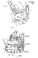
- Fig. 1 shows an adhesive applying device having a pair of upper and lower adhesive injection nozzles D, D and a cutting device E arranged one behind the other on the side of a conveyance passage C.
- the cutting device E for cutting from a continuous strip the auxiliary articles to be packaged such as straws comprises a cutting drum 1 being intermittently"rotated and a cutter 2 capable of entering in slots la of the drum.
- the intermittent rotation of the cutting drum 1 supplies a continuous strip B of equispaced articles d by steps of predetermined distance by the distance corresponding to the spacing of the articles.
- a cylinder 3 moves the cutter 2 into a corresponding slot la, thereby cutting the narrow strip of continuous articles to be packaged B into individual package articles b, and, at the same time, the rotation of the cutting drum 1 consecutively feeds out the package articles b.
- An expanded part d of the strip B enwrapping the auxiliary articles b is fitted in each of feed grooves 1b formed between the slots la of the cutting drum 1.
- another system may be used wherein when a rotating cutter passes a slot while the drum is revolving.
- a cam wheel 4 is fixed concentrically to a shaft 1c of the cutting drum 1 and cooperates alternating with two pins 5a and 5b which are disposed on the outside of the cam wheel 4 and actuated by two cylinders 6a and 6b to enter alternatingly into the recess of grooves 4b having inclined driving side wells 4a.
- Fig. 2 illustrates the state wherein the pin 5b fully entered in a groove 4b of the cam wheel 4 and, when the cylinder is actuated, said pin 5b moves out of the groove.
- the strip B holding the articles to be packaged is adapted to be fed through a guide roller 7 and a guide surface 9 of an attachment 8 as shown in Fig. 3 to the cutting drum 1.
- levers 10 are provided for taking off the individual package articles b which have been cut by the cutter 2 from th periphery of the cutting drum 1 and pushing them towards the side face of the food packaging containers A and A' which are fed past the side thereof.
- Said levers 10 are adapted to be swingingly moved with the shaft 10a as a fulcrum by actuation of a cylinder 11.
- the cutting device E is, as shown in Figs. 2 to 4, formed as one unit which is mounted to a plate 12 disposed on the side of the conveyance passage C as shown in Fig. 1.
- a bracket 13 as shown in Fig. 6 is fixed to a frame F located at the side of the conveyance passage C, and a guide member 14 is mounted to said bracket 13 by fastening means 15.
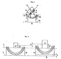
- a guide section 13a is formed which projects inwardly and is arc-shaped, the arc being concentric to the center (shown by 0 in Figs. 8-1010) of the side face of a food packaging container A which is fed through the conveyance passage C (usable as a conveyor).
- the guide surface 13 is adjacent to a guide slot 13b.
- the guide member 14 is fixed to the bracket 13, according to the embodiment such that the fasteners (bolts) 15 are inserted from the back side through the guide slot 13b and are screwed in screw holes 14a provided on the back side of the guide member 14.
- the lower surface of the guide member 14 is arc-shaped, for fitting with the guide surface 13a formed on the bracket 13. To alter the mounting position on the guide surface 13a of the bracket 13, after loosening the fasteners (bolts) 15, the guide member 14 is moved along the guide surface 13a of the bracket 13 and after reaching the desired position, the fasteners (bolts) 15 are fastened.
- FIGs. 8 and 9 illustrate the case where the guide member 14 is set to the limit at the left end, at the riot end of the bracket 13, respectively the corresponding physical angles of the cutting . device E, mounted as a unit to the member to be guided 14, being reversive to each other.
- the shaft line of the cutting drum 1 of the cutting device E to be located on the line passing the center 0 of the side face of the food packaging container A which is fed through the conveyance passage C.
- the axis of the cutting drum 1 may come to be located along the diagonals L 1 and L 2 of the food packaging container A, and the cutting device E will enable the package article b to be adhered at a position where it is in line with the diagonal L 1 or L 2 of the side face of the food packaging container A.
- a pair of upper and lower adhesive injection nozzles D, D are shown to be mounted to the guide member 14.
- the pair of adhesive injection nozzles D, D can be positioned on a line passing the center 0 of the side face of the food packaging container A which is fed through the conveyance passage C and in particular, if the guide member 14 is set to the position shown by a full line of Fig.
- the pair of adhesive injection nozzles D, D can be positioned to the diagonals L 1 and L 2 of the food packaging container A for applying the adhesive to two points on the diagonals L 1 and L 2 .
- the article b thereon By pressing the article b thereon, it can be adhered in a position where it is just in line with the diagonal of the side face of the food packaging container A.
- both the guide surface 13a, internally projected and arc-shaped, and the arc-shaped guide slot 13b are used in common.
- the guide section may use only either of the guide surface 13a or the guide slot 13b. If only the guide surface 13a is formed without provision of the guide slot 13b, it may be necessary to shape the lower surface of the guide member 14 to be internally projected and arc-shaped identically to the form of said guide surface 13a.
- Fig. 11 illustrates how to mount the bracket 13 in the case where the size of the food packaging container which is fed through the conveyance passage C is different.
- the distance H from the conveyance passage C to the center 0 of the small food packaging container A which is conveyed is different from the distance H' from the conveyance passage C to the center 0 1 of a larger food packaging container A' which is conveyed.
- the bracket 13 used when handling the smaller food packaging container A cannot be utilized for the case where the larger food packaging container A' is handled without modifying the bracket or using annother bracket.
- the auxiliary base 16 possessing a thickness h is put on the frame F, and the bracket 13 used for the small food packaging container A is mounted thereto.
- bracket 13 used for the case where the smaller containers A are handled can be utilized also for the case where the larger containers A' are handled. This offers the convenience that manufacturing of different special brackets is not necessary.
- the present invention it is possible to alter easily and accurately the physical angle of the device disposed on the side of the conveyance passage with respect to the commodities transferred thereon.
- the present invention enables the above-mentioned device to be easily and accurately disposed along a line passing through the center of the side face of the commodity to be transferred.
Landscapes
- Engineering & Computer Science (AREA)
- Mechanical Engineering (AREA)
- Auxiliary Devices For And Details Of Packaging Control (AREA)
Applications Claiming Priority (2)
| Application Number | Priority Date | Filing Date | Title |
|---|---|---|---|
| JP59190450A JPS6169528A (ja) | 1984-09-10 | 1984-09-10 | 移送物品に対する体位変更装置 |
| JP190450/84 | 1984-09-10 |
Publications (2)
| Publication Number | Publication Date |
|---|---|
| EP0176000A1 true EP0176000A1 (fr) | 1986-04-02 |
| EP0176000B1 EP0176000B1 (fr) | 1988-11-23 |
Family
ID=16258331
Family Applications (1)
| Application Number | Title | Priority Date | Filing Date |
|---|---|---|---|
| EP85111435A Expired EP0176000B1 (fr) | 1984-09-10 | 1985-09-10 | Appareil pour fixer des objets auxiliaires à des articles de consommation |
Country Status (5)
| Country | Link |
|---|---|
| US (1) | US4669699A (fr) |
| EP (1) | EP0176000B1 (fr) |
| JP (1) | JPS6169528A (fr) |
| KR (1) | KR930005057B1 (fr) |
| DE (1) | DE3566382D1 (fr) |
Cited By (1)
| Publication number | Priority date | Publication date | Assignee | Title |
|---|---|---|---|---|
| EP0305789A1 (fr) * | 1987-09-04 | 1989-03-08 | Aktiebolaget PROFOR | Appareil et procédé pour l'application d'objets oblongs et flexibles sur des récipients d'emballage |
Families Citing this family (11)
| Publication number | Priority date | Publication date | Assignee | Title |
|---|---|---|---|---|
| JP2738438B2 (ja) * | 1988-11-25 | 1998-04-08 | 義章 清水 | ストローアプリケート装置 |
| US5037366A (en) * | 1990-05-17 | 1991-08-06 | Gilliland Industrials Corporation | Device for attaching a straw to a carton container |
| SE468008B (sv) * | 1991-02-01 | 1992-10-19 | Tetra Alfa Holdings | Anordning foer att styra banformigt sammanhaengande foeremaal vid applicering paa foerpackningsbehaallare |
| DE4114191C1 (en) * | 1991-05-01 | 1992-04-23 | Ostma Maschinenbau Gmbh, 5352 Zuelpich, De | Application of long strip of material - involves conveyor belt and associated pressure and counter-pressure belts |
| DE4220634C2 (de) * | 1992-06-24 | 1996-04-11 | Daimler Benz Aerospace Ag | Justiervorrichtung |
| US5556217A (en) * | 1994-07-11 | 1996-09-17 | Clark Equipment Company | Auger mount |
| DE19745855C2 (de) * | 1997-10-16 | 2002-06-20 | Indag Gmbh | Trinkhalmanbringvorrichtung und Verfahren zum Anbringen von Trinkhalmen an Getränkefolienbeutel |
| US6526725B1 (en) * | 1999-06-23 | 2003-03-04 | Shrink Packaging Systems Corporation | Apparatus and method for attaching straws to containers |
| DE19952008A1 (de) * | 1999-10-28 | 2001-05-10 | Indag Gmbh | Vorrichtung zum Anbringen von Trinkhalmen |
| JP5509682B2 (ja) * | 2009-06-03 | 2014-06-04 | 株式会社コオエイ | ストロー貼着装置 |
| ES3012082T3 (en) * | 2021-01-13 | 2025-04-08 | Ecolean Ab | Device for applying an article to a moving object |
Citations (2)
| Publication number | Priority date | Publication date | Assignee | Title |
|---|---|---|---|---|
| FR2415576A1 (fr) * | 1978-01-30 | 1979-08-24 | Tetra Pak Int | Machine pour l'application de chalumeaux d'aspiration sur des recipients d'emballage |
| EP0117920A2 (fr) * | 1982-12-24 | 1984-09-12 | Ab Tetra Pak | Appareil pour effectuer une opération de traitement |
Family Cites Families (8)
| Publication number | Priority date | Publication date | Assignee | Title |
|---|---|---|---|---|
| DE11140C (de) * | M. NEUERBURG in Köln und C. TRAUTZ in Dillstein bei Pforzheim | Neuerung an Gestellen für Gesteinbohrmaschinen | ||
| US1703099A (en) * | 1923-07-31 | 1929-02-26 | Frederick L Craddock | Mixing device |
| US2255514A (en) * | 1939-10-07 | 1941-09-09 | Mixing Equipment Co Inc | Supporting bracket |
| US2298087A (en) * | 1940-08-02 | 1942-10-06 | Bell & Howell Co | Adjustable support mechanism |
| US2386906A (en) * | 1943-12-04 | 1945-10-16 | Western Electric Co | Tilting apparatus |
| US2594404A (en) * | 1949-04-07 | 1952-04-29 | Debrie Andre Victor Le Clement | Support for motion-picture apparatus and the like |
| DE3204011A1 (de) * | 1982-02-05 | 1983-08-11 | Geyssel, Jürgen, 5000 Köln | Vorrichtung zum anbringen von gegenstaenden an packungen, flaschen oder anderen objekten |
| SE454681B (sv) * | 1983-06-23 | 1988-05-24 | Tetra Pak Ab | Anordning for applicering av foremal pa forpackningsbehallare |
-
1984
- 1984-09-10 JP JP59190450A patent/JPS6169528A/ja active Granted
-
1985
- 1985-09-09 KR KR1019850006567A patent/KR930005057B1/ko not_active Expired - Fee Related
- 1985-09-09 US US06/774,236 patent/US4669699A/en not_active Expired - Lifetime
- 1985-09-10 DE DE8585111435T patent/DE3566382D1/de not_active Expired
- 1985-09-10 EP EP85111435A patent/EP0176000B1/fr not_active Expired
Patent Citations (2)
| Publication number | Priority date | Publication date | Assignee | Title |
|---|---|---|---|---|
| FR2415576A1 (fr) * | 1978-01-30 | 1979-08-24 | Tetra Pak Int | Machine pour l'application de chalumeaux d'aspiration sur des recipients d'emballage |
| EP0117920A2 (fr) * | 1982-12-24 | 1984-09-12 | Ab Tetra Pak | Appareil pour effectuer une opération de traitement |
Cited By (1)
| Publication number | Priority date | Publication date | Assignee | Title |
|---|---|---|---|---|
| EP0305789A1 (fr) * | 1987-09-04 | 1989-03-08 | Aktiebolaget PROFOR | Appareil et procédé pour l'application d'objets oblongs et flexibles sur des récipients d'emballage |
Also Published As
| Publication number | Publication date |
|---|---|
| KR930005057B1 (ko) | 1993-06-15 |
| KR860002411A (ko) | 1986-04-24 |
| US4669699A (en) | 1987-06-02 |
| DE3566382D1 (en) | 1988-12-29 |
| EP0176000B1 (fr) | 1988-11-23 |
| JPH0471775B2 (fr) | 1992-11-16 |
| JPS6169528A (ja) | 1986-04-10 |
Similar Documents
| Publication | Publication Date | Title |
|---|---|---|
| US7398871B1 (en) | Outsert placer | |
| US5078826A (en) | Labelling machine for the labelling of containers | |
| US4473429A (en) | High speed wrap around label applicator and method | |
| EP0176000B1 (fr) | Appareil pour fixer des objets auxiliaires à des articles de consommation | |
| US4143754A (en) | Labelling machines with article guide plate | |
| KR900005032B1 (ko) | 팩용기에 음료 빨대를 부착하는 방법 및 그 방법을 실시하는 장치 | |
| EP0935560B1 (fr) | Dispositif pour placer de la documentation sur des articles | |
| JPH07503216A (ja) | ラベル貼付装置 | |
| US4443285A (en) | Tapered article labelling machine and method | |
| JPS59142932A (ja) | 粘着性ラベル取付装置 | |
| CA1140899A (fr) | Machines a etiqueter | |
| US4108706A (en) | Labelling machine | |
| WO1996009213A3 (fr) | Machine a etiqueter | |
| US4338155A (en) | Method and apparatus for indexing containers to be labeled | |
| JPH0764423B2 (ja) | 物品搬送装置 | |
| US4747905A (en) | Labelling apparatus | |
| US4919747A (en) | Label applying devices for applying adhesive labels to articles | |
| US7946098B1 (en) | Apparatus for applying drinking straws | |
| US5336359A (en) | System for applying literature to a wall of an object | |
| US6213185B1 (en) | Feeder for outserts and other articles | |
| US4641481A (en) | Device for cutting a narrow strip of continuous articles for packaging | |
| US4569185A (en) | Self-adjusting packaging machine | |
| CN112969645B (zh) | 用于在包装器件或包装器件组上附接提手部的设备和方法 | |
| US20120227906A1 (en) | High-speed outsert placer | |
| US3393490A (en) | Method and apparatus for assembling packages |
Legal Events
| Date | Code | Title | Description |
|---|---|---|---|
| PUAI | Public reference made under article 153(3) epc to a published international application that has entered the european phase |
Free format text: ORIGINAL CODE: 0009012 |
|
| AK | Designated contracting states |
Kind code of ref document: A1 Designated state(s): BE CH DE FR GB IT LI NL SE |
|
| RHK1 | Main classification (correction) |
Ipc: C21B 13/00 |
|
| 17P | Request for examination filed |
Effective date: 19860626 |
|
| RAP1 | Party data changed (applicant data changed or rights of an application transferred) |
Owner name: AB TETRA PAK |
|
| 17Q | First examination report despatched |
Effective date: 19870611 |
|
| GRAA | (expected) grant |
Free format text: ORIGINAL CODE: 0009210 |
|
| AK | Designated contracting states |
Kind code of ref document: B1 Designated state(s): BE CH DE FR GB IT LI NL SE |
|
| REF | Corresponds to: |
Ref document number: 3566382 Country of ref document: DE Date of ref document: 19881229 |
|
| ITF | It: translation for a ep patent filed | ||
| ET | Fr: translation filed | ||
| RAP2 | Party data changed (patent owner data changed or rights of a patent transferred) |
Owner name: AB TETRA PAK |
|
| PLBE | No opposition filed within time limit |
Free format text: ORIGINAL CODE: 0009261 |
|
| STAA | Information on the status of an ep patent application or granted ep patent |
Free format text: STATUS: NO OPPOSITION FILED WITHIN TIME LIMIT |
|
| 26N | No opposition filed | ||
| ITTA | It: last paid annual fee | ||
| EAL | Se: european patent in force in sweden |
Ref document number: 85111435.5 |
|
| PGFP | Annual fee paid to national office [announced via postgrant information from national office to epo] |
Ref country code: NL Payment date: 19980825 Year of fee payment: 14 |
|
| PGFP | Annual fee paid to national office [announced via postgrant information from national office to epo] |
Ref country code: GB Payment date: 19980826 Year of fee payment: 14 |
|
| PGFP | Annual fee paid to national office [announced via postgrant information from national office to epo] |
Ref country code: BE Payment date: 19980914 Year of fee payment: 14 |
|
| PGFP | Annual fee paid to national office [announced via postgrant information from national office to epo] |
Ref country code: CH Payment date: 19981005 Year of fee payment: 14 |
|
| PG25 | Lapsed in a contracting state [announced via postgrant information from national office to epo] |
Ref country code: GB Free format text: LAPSE BECAUSE OF NON-PAYMENT OF DUE FEES Effective date: 19990910 |
|
| PG25 | Lapsed in a contracting state [announced via postgrant information from national office to epo] |
Ref country code: LI Free format text: LAPSE BECAUSE OF NON-PAYMENT OF DUE FEES Effective date: 19990930 Ref country code: CH Free format text: LAPSE BECAUSE OF NON-PAYMENT OF DUE FEES Effective date: 19990930 Ref country code: BE Free format text: LAPSE BECAUSE OF NON-PAYMENT OF DUE FEES Effective date: 19990930 |
|
| BERE | Be: lapsed |
Owner name: A.B. TETRA PAK Effective date: 19990930 |
|
| PG25 | Lapsed in a contracting state [announced via postgrant information from national office to epo] |
Ref country code: NL Free format text: LAPSE BECAUSE OF NON-PAYMENT OF DUE FEES Effective date: 20000401 |
|
| GBPC | Gb: european patent ceased through non-payment of renewal fee |
Effective date: 19990910 |
|
| REG | Reference to a national code |
Ref country code: CH Ref legal event code: PL |
|
| NLV4 | Nl: lapsed or anulled due to non-payment of the annual fee |
Effective date: 20000401 |
|
| PGFP | Annual fee paid to national office [announced via postgrant information from national office to epo] |
Ref country code: FR Payment date: 20010817 Year of fee payment: 17 |
|
| PG25 | Lapsed in a contracting state [announced via postgrant information from national office to epo] |
Ref country code: FR Free format text: LAPSE BECAUSE OF NON-PAYMENT OF DUE FEES Effective date: 20030603 |
|
| REG | Reference to a national code |
Ref country code: FR Ref legal event code: ST |
|
| PGFP | Annual fee paid to national office [announced via postgrant information from national office to epo] |
Ref country code: SE Payment date: 20030919 Year of fee payment: 19 |
|
| PGFP | Annual fee paid to national office [announced via postgrant information from national office to epo] |
Ref country code: DE Payment date: 20031031 Year of fee payment: 19 |
|
| PG25 | Lapsed in a contracting state [announced via postgrant information from national office to epo] |
Ref country code: SE Free format text: LAPSE BECAUSE OF NON-PAYMENT OF DUE FEES Effective date: 20040911 |
|
| PG25 | Lapsed in a contracting state [announced via postgrant information from national office to epo] |
Ref country code: DE Free format text: LAPSE BECAUSE OF NON-PAYMENT OF DUE FEES Effective date: 20050401 |
|
| EUG | Se: european patent has lapsed |