EP0176006A1 - Scie à panneaux avec un bâti vertical - Google Patents
Scie à panneaux avec un bâti vertical Download PDFInfo
- Publication number
- EP0176006A1 EP0176006A1 EP19850111511 EP85111511A EP0176006A1 EP 0176006 A1 EP0176006 A1 EP 0176006A1 EP 19850111511 EP19850111511 EP 19850111511 EP 85111511 A EP85111511 A EP 85111511A EP 0176006 A1 EP0176006 A1 EP 0176006A1
- Authority
- EP
- European Patent Office
- Prior art keywords
- workpiece
- driver
- panel saw
- saw
- finger
- Prior art date
- Legal status (The legal status is an assumption and is not a legal conclusion. Google has not performed a legal analysis and makes no representation as to the accuracy of the status listed.)
- Withdrawn
Links
- 208000029154 Narrow face Diseases 0.000 abstract 1
- 239000000356 contaminant Substances 0.000 description 2
- 210000000056 organ Anatomy 0.000 description 1
- 238000007790 scraping Methods 0.000 description 1
Images


Classifications
-
- B—PERFORMING OPERATIONS; TRANSPORTING
- B27—WORKING OR PRESERVING WOOD OR SIMILAR MATERIAL; NAILING OR STAPLING MACHINES IN GENERAL
- B27B—SAWS FOR WOOD OR SIMILAR MATERIAL; COMPONENTS OR ACCESSORIES THEREFOR
- B27B31/00—Arrangements for conveying, loading, turning, adjusting, or discharging the log or timber, specially designed for saw mills or sawing machines
-
- B—PERFORMING OPERATIONS; TRANSPORTING
- B27—WORKING OR PRESERVING WOOD OR SIMILAR MATERIAL; NAILING OR STAPLING MACHINES IN GENERAL
- B27B—SAWS FOR WOOD OR SIMILAR MATERIAL; COMPONENTS OR ACCESSORIES THEREFOR
- B27B5/00—Sawing machines working with circular or cylindrical saw blades; Components or equipment therefor
- B27B5/02—Sawing machines working with circular or cylindrical saw blades; Components or equipment therefor characterised by a special purpose only
- B27B5/06—Sawing machines working with circular or cylindrical saw blades; Components or equipment therefor characterised by a special purpose only for dividing plates in parts of determined size, e.g. panels
- B27B5/065—Sawing machines working with circular or cylindrical saw blades; Components or equipment therefor characterised by a special purpose only for dividing plates in parts of determined size, e.g. panels with feedable saw blades, e.g. arranged on a carriage
- B27B5/07—Sawing machines working with circular or cylindrical saw blades; Components or equipment therefor characterised by a special purpose only for dividing plates in parts of determined size, e.g. panels with feedable saw blades, e.g. arranged on a carriage the plate being positioned in a substantially vertical plane
Definitions
- the invention relates to a panel saw according to the preamble of claim 1.
- a panel saw of the type mentioned is known, in which drivable conveyor belts are provided for the workpiece at the lower end of the support device, with which the workpiece can be conveyed against a stop.
- a circular saw is provided for making only vertical cuts, which is slidably mounted on vertical guides.
- the object of the present invention is therefore to create a panel saw of the type mentioned, in which the workpiece is safely conveyed against a stop and in which this is supported on its lower narrow surface by an absolutely straight support.
- driver finger results in a non-positive connection between the driver device and the workpiece, so that it is pushed securely against the stop.
- Supporting strips or support rollers can be used to support the lower narrow surface of the workpiece, so that the workpiece lies absolutely flat and a precise, vertical cut is ensured.
- the foldable driver finger allows the panel saw to be loaded with the workpiece unhindered. It is also equipped with a brush, which is automatically used for pre- or. Return cleans the support organs of chips and other contaminants. This ensures that the workpieces are divided accurately.
- the driver element here a driver chain
- the driver element can be driven according to the invention by an infinitely variable electric drive which can be controlled via a hand switch. This can be taken to the respective work station, so that the feed of the workpiece can be easily controlled, the pushing speed of the workpiece can be entered accelerated or decelerated, so that a smooth approach to the longitudinal stop is guaranteed.
- a guide bar 2 is horizontally slidably mounted on an upright frame 1.
- a saw carriage 3 can be moved in the vertical direction with a circular saw 4 and thus a workpiece 5 can be divided by vertical saw cuts 6.
- the guide bar 2 is firmly locked to the frame 1.
- the guide bar 2 is unlocked in a known manner and the circular saw 4 is pivoted into a horizontal position, so that the workpiece 5 can be divided by moving the guide bar 2 by means of horizontal saw cuts.
- the lower narrow surface 7 of workpiece 5 rests on support members 8 in the form of a support bar.
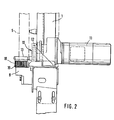
- a driver device 10 which has a driver element 12 in the form of a driver chain which can be driven by an electric motor 11, is used to move workpiece 5 against a displaceable stop 9 connected to the frame.
- This driver device is mounted in the vicinity of the support members 8 and a driver finger 13 is connected to the driver member 12, which extends perpendicular to the support surface for the workpiece 5 in the driver position. It grips behind the vertical narrow surface of workpiece 5 and supports it against stop 9.
- the electric motor 11 can be controlled by a portable hand switch 14 in such a way that the stop 9 is smoothly started by the workpiece 5.
- the driving finger 13 is pivotally mounted on the driving element 12 so that in its end position it can be pivoted from a driving position perpendicular to the support surface into a position parallel to it.
- a control plate 15 with a control cam 16 is attached to the frame 1, against which the driver finger 13 abuts during its backward movement and is thus folded down.
- the control cam 16 releases it again and it is folded back into its driver position under the action of a return spring 17.
- the driver finger 13 is provided with a p r scraping brush 18 which cleans the support surface 19 of the support members 8 of chips and other contaminants during the forward and backward movement of the driver device 10. This guarantees a perfect support of the workpiece and thus a dimensionally accurate division.
- a limit switch 20 is arranged on the frame 1, with the push button 21 of which the driver finger 13 interacts.
- limit switch 20 is actuated, electric motor 11 is thus switched off.
Landscapes
- Life Sciences & Earth Sciences (AREA)
- Engineering & Computer Science (AREA)
- Mechanical Engineering (AREA)
- Wood Science & Technology (AREA)
- Forests & Forestry (AREA)
- Sawing (AREA)
Applications Claiming Priority (2)
| Application Number | Priority Date | Filing Date | Title |
|---|---|---|---|
| DE3435211 | 1984-09-26 | ||
| DE19843435211 DE3435211A1 (de) | 1984-09-26 | 1984-09-26 | Plattensaege mit aufrechtem gestell |
Publications (1)
| Publication Number | Publication Date |
|---|---|
| EP0176006A1 true EP0176006A1 (fr) | 1986-04-02 |
Family
ID=6246341
Family Applications (1)
| Application Number | Title | Priority Date | Filing Date |
|---|---|---|---|
| EP19850111511 Withdrawn EP0176006A1 (fr) | 1984-09-26 | 1985-09-11 | Scie à panneaux avec un bâti vertical |
Country Status (2)
| Country | Link |
|---|---|
| EP (1) | EP0176006A1 (fr) |
| DE (1) | DE3435211A1 (fr) |
Cited By (2)
| Publication number | Priority date | Publication date | Assignee | Title |
|---|---|---|---|---|
| EP0602574A1 (fr) * | 1992-12-16 | 1994-06-22 | REICH SPEZIALMASCHINEN GmbH | Scie à panneaux à bâti vertical |
| EP1321252A3 (fr) * | 2001-12-17 | 2004-05-26 | HOLZMA Plattenaufteiltechnik GmbH | Dispositif de poussoir/butée pour scies à découper des plaques |
Families Citing this family (1)
| Publication number | Priority date | Publication date | Assignee | Title |
|---|---|---|---|---|
| AT397483B (de) * | 1992-07-29 | 1994-04-25 | Spiessberger Franz | Plattensäge mit aufrechtem gestell |
Citations (3)
| Publication number | Priority date | Publication date | Assignee | Title |
|---|---|---|---|---|
| US3111148A (en) * | 1960-04-14 | 1963-11-19 | Fred L Herrmann | Duplicator stand with router |
| DE2305673A1 (de) * | 1973-02-06 | 1974-08-22 | Reich Maschf Gmbh Karl | Vertikale plattenkreissaege |
| DE2713209A1 (de) * | 1977-03-25 | 1978-10-05 | Ludolf Stegherr | Saegewagen |
-
1984
- 1984-09-26 DE DE19843435211 patent/DE3435211A1/de not_active Withdrawn
-
1985
- 1985-09-11 EP EP19850111511 patent/EP0176006A1/fr not_active Withdrawn
Patent Citations (3)
| Publication number | Priority date | Publication date | Assignee | Title |
|---|---|---|---|---|
| US3111148A (en) * | 1960-04-14 | 1963-11-19 | Fred L Herrmann | Duplicator stand with router |
| DE2305673A1 (de) * | 1973-02-06 | 1974-08-22 | Reich Maschf Gmbh Karl | Vertikale plattenkreissaege |
| DE2713209A1 (de) * | 1977-03-25 | 1978-10-05 | Ludolf Stegherr | Saegewagen |
Cited By (2)
| Publication number | Priority date | Publication date | Assignee | Title |
|---|---|---|---|---|
| EP0602574A1 (fr) * | 1992-12-16 | 1994-06-22 | REICH SPEZIALMASCHINEN GmbH | Scie à panneaux à bâti vertical |
| EP1321252A3 (fr) * | 2001-12-17 | 2004-05-26 | HOLZMA Plattenaufteiltechnik GmbH | Dispositif de poussoir/butée pour scies à découper des plaques |
Also Published As
| Publication number | Publication date |
|---|---|
| DE3435211A1 (de) | 1986-04-03 |
Similar Documents
| Publication | Publication Date | Title |
|---|---|---|
| DE3621357C1 (de) | Kappsaege zum Ablaengen von Brettern | |
| DE3736509A1 (de) | Vorrichtung zum laminieren und schneiden von fotoresistbahnen | |
| DE1527304A1 (de) | Schneidvorrichtung | |
| CH658814A5 (de) | Tafelschere. | |
| DE2709738A1 (de) | Brennschneidmaschine | |
| AT396767B (de) | Kreissäge mit automatischem abtransport des schnittgutes | |
| DE8014234U1 (de) | Besaeumvorrichtung fuer plattensaegen zum besaeumen von aus einer ein- oder beidseitig mit einer deckschicht beschichteten traegerplatte bestehenden werkstuecken | |
| EP0176006A1 (fr) | Scie à panneaux avec un bâti vertical | |
| DE2330476A1 (de) | Plattenaufteileinrichtung | |
| DE4002116C2 (de) | Gurthobel | |
| DE1652760B2 (de) | Fuer eine tafelschere fuer tafeln aus blech, kunststoff o.dgl. bestimmte vorrichtung zum unterstuetzen und abfuehren der geschnittenen tafeln | |
| DE3417963C2 (fr) | ||
| DE7100994U (de) | Format und Aufteilsage | |
| DE2521531C3 (de) | Formataufteilsäge | |
| EP0026755A1 (fr) | Dispositif d'amenée pour machines à travailler les tôles | |
| DE935947C (de) | Vorrichtung fuer Naehmaschinen zum Fuehren aufeinanderliegender und miteinander zu vernaehender Stoffteile | |
| EP0221289B1 (fr) | Machine à travailler le bois, en particulier des poutres de fenêtre et des poutres similaires | |
| DE4310270A1 (de) | Handhobelmaschine | |
| CH574314A5 (en) | Self propelled saw for dividing boards - has side support table pivoting relative to machine table | |
| DE3225530A1 (de) | Schneideinrichtung fuer querschnittsduenne glastafeln | |
| DE3717207A1 (de) | Kappvorrichtung fuer kantenanleimmaschinen | |
| DE19811669C2 (de) | Klinkschnittsäge | |
| DE4424940C2 (de) | Verfahren zur Bearbeitung von Holzwerkstücken | |
| DE2938700C3 (de) | Stapelgerät | |
| CH632218A5 (en) | Workpiece-oriented width-setting device |
Legal Events
| Date | Code | Title | Description |
|---|---|---|---|
| PUAI | Public reference made under article 153(3) epc to a published international application that has entered the european phase |
Free format text: ORIGINAL CODE: 0009012 |
|
| AK | Designated contracting states |
Kind code of ref document: A1 Designated state(s): AT BE CH FR GB IT LI NL SE |
|
| 17P | Request for examination filed |
Effective date: 19860821 |
|
| 17Q | First examination report despatched |
Effective date: 19871029 |
|
| STAA | Information on the status of an ep patent application or granted ep patent |
Free format text: STATUS: THE APPLICATION IS DEEMED TO BE WITHDRAWN |
|
| 18D | Application deemed to be withdrawn |
Effective date: 19880309 |
|
| RIN1 | Information on inventor provided before grant (corrected) |
Inventor name: DETTELBACH, ALFRED |