EP0176125A1 - Dispositif à installer une surface d'appui - Google Patents
Dispositif à installer une surface d'appui Download PDFInfo
- Publication number
- EP0176125A1 EP0176125A1 EP19850201388 EP85201388A EP0176125A1 EP 0176125 A1 EP0176125 A1 EP 0176125A1 EP 19850201388 EP19850201388 EP 19850201388 EP 85201388 A EP85201388 A EP 85201388A EP 0176125 A1 EP0176125 A1 EP 0176125A1
- Authority
- EP
- European Patent Office
- Prior art keywords
- film
- fixing element
- pins
- object according
- supporting surface
- Prior art date
- Legal status (The legal status is an assumption and is not a legal conclusion. Google has not performed a legal analysis and makes no representation as to the accuracy of the status listed.)
- Withdrawn
Links
Images


Classifications
-
- F—MECHANICAL ENGINEERING; LIGHTING; HEATING; WEAPONS; BLASTING
- F16—ENGINEERING ELEMENTS AND UNITS; GENERAL MEASURES FOR PRODUCING AND MAINTAINING EFFECTIVE FUNCTIONING OF MACHINES OR INSTALLATIONS; THERMAL INSULATION IN GENERAL
- F16B—DEVICES FOR FASTENING OR SECURING CONSTRUCTIONAL ELEMENTS OR MACHINE PARTS TOGETHER, e.g. NAILS, BOLTS, CIRCLIPS, CLAMPS, CLIPS OR WEDGES; JOINTS OR JOINTING
- F16B47/00—Suction cups for attaching purposes; Equivalent means using adhesives
- F16B47/003—Suction cups for attaching purposes; Equivalent means using adhesives using adhesives for attaching purposes
-
- A—HUMAN NECESSITIES
- A47—FURNITURE; DOMESTIC ARTICLES OR APPLIANCES; COFFEE MILLS; SPICE MILLS; SUCTION CLEANERS IN GENERAL
- A47G—HOUSEHOLD OR TABLE EQUIPMENT
- A47G1/00—Mirrors; Picture frames or the like, e.g. provided with heating, lighting or ventilating means
- A47G1/16—Devices for hanging or supporting pictures, mirrors, or the like
- A47G1/17—Devices for hanging or supporting pictures, mirrors, or the like using adhesives, suction or magnetism
Definitions
- the invention relates to an object to be mounted on a supporting surface, for example a wall, which object is a fixing element, conductor, hose or similar to which is bonded a film protruding out of the object and which can be adhered to the supporting surface.
- the film has openings, pores, recesses or similar, which are suitable for absorption of adhesive.
- the film preferably consists of a woven material or a gauze-type material.
- a material is particularly good for application to uneven surfaces, since this material can easily follow the unevennesses, so that a particularly good bond will be obtained, so that a high adhesive strength can be obtained even with relatively small dimensions, so that even heavy objects can be suspended.
- This piece of fabric is however supported over its' whole surface by the fixing element in question and does not protruob outside of the fixing element, as a result of which a good adaptation of the woven material to the unevennesses of the supporting surface cannot be obtained with this design.
- the fixing element illustrated in fig. 1 is formed by a cross-shaped fixing element 1, which is manufactured for example from plastic or similar material and adhered to a film 2 manufactured from flexible material.
- the film 2 can for example be manufactured from linen or canvas or from a gauze-type material.
- the film may be manufactured from synthetic or natural fibres. It may also be possible for so-called non-woven materials to be used for the film.
- the fixing element 1 should preferably be moulded on the film 2, as a result of which a particularly good adhesion should be obtained between the fixing element 1 and the film 2.
- a hole 3 provided in the centre of the cross-shaped fixing element 1, in which, for example, a screw, a suspension hook or similar can be secured.
- the fixing element 1 can be secured to a surface, for example a brick wall or similar, whereby the film 2 is smeared over with a suitable adhesive, which adhesive by the nature of the film-like material can also penetrate into the pores or openings bordered by the fibres from which the film 2 is manufactured. An excellent bonding will therefore be obtained between the adhesive and the film 2.
- the film 2 can by virtue of its flexible nature adapt well to any unevennesses in the supporting surface to which the film 2 is applied, such that a firm connection will so be achieved with the aid of the adhesive between the film 2 and the supporting surface and thus between the supporting surface and the fixing element.
- the film may also be provided with a self-adhesive coating during its manufacture, which coating will often be provided with a protective covering for the purposes of transport and storage.
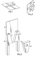
- So fig. 2 shows an embodiment whereby a cross-shaped fixing element 5 joined to a film 4 is provided with a projecting pin 6, a hole 7 located at the centre of this cross-shaped fixing element and a hole 8 having the form of a keyhole.
- a cross-shaped fixing element 5 joined to a film 4 is provided with a projecting pin 6, a hole 7 located at the centre of this cross-shaped fixing element and a hole 8 having the form of a keyhole.
- the centrally located hole 7 can be used in a similar way to the hole 3, whilst the pin 6 may also be used for the attachment of the elements or similar to be suspended.
- Other arrangements of the holes and/or pins are of course possible.
- Fig. 3 shows an embodiment whereby the uppermost piece of an essentially H-shaped part 10 of the fixing element is fixed to a film 9 manufactured from flexible material.
- the top parts of the legs of the H-shaped part 10 define an opening 11 tapering downwards.
- the upright walls defining the opening 11 thereby extend obliquely outwards from the film, in a direction towards each other.
- a correspondingly shaped part 12 of the fixing element whereby such part 12 can be inserted from above into the opening 11.
- a hole 13 provided in part 12 for the insertion of a screw or similar.
- part 12 may also be provided with other means, such as projecting pins, hook-shaped parts or similar for the suspension of objects or the like from the fixing element.
- fixing elements are formed by a cross-shaped part 14, which is secured to a flexible film 15 in such a way that the bottommost section of the vertically upright leg of the cross-shaped section 14 projects underneath the film 15.
- the fixing element comprises a first, essentially H-shaped section 18, which is made from two legs extending parallel to each other and a centre piece 20 joining said legs 19.
- This part 18 of the fixing element is secured to a ribbon-like film 21 manufactured from flexible material, which extends-between the legs and through the middle section 20.
- This connecting section 18 is manufactured for example from plastic by injection moulding, whereby the material forming the centre section 20 is simultaneously injected around the ribbon-like film 21, so that on the moulding of part 18 of the fixing element firm bond is achieved at the same time with the ribbon-like film 21.
- the fixing element comprises a second plate-like section 22, which on the one side is provided with four projecting pins 23, fitting by means of press fit into the legs 19 of the holes 24 recessed in part 18.
- a projecting hook 25 is formed, whilst a keyhole shaped hole 26 is recessed at a further place on the plate-shaped part.
- parts 18 and part 22 are joined together by a number of connecting strips 27, which are formed during the injection moulding of both parts 18 and 22 in a single mould.
- a large number of such fixing elements consisting of the parts 18 and 22 are moulded onto a length of ribbon-like film 21 and, if a fixing element is required for use, the appropriate portion of the length of ribbon 21 can be cut off. Subsequently the parts 18 and 22 can be separated from each other by breaking off the connecting strips and, when the flexible section of the ribbon-like element 21 joined to the corresponding part 18 has been adhered to the supporting surface, the plate-like section 22 can be fixed to the part 18 by pressing the pins 23 into the holes 24.
- the hook-shaped section 25 or the keyhole-shaped opening 26 can be used for example for the suspension of objects from the fixing element.
- the fixing element shown in fig. 7 comprises a cross-shaped body 30 of plastic, provided with a central hole 31, for example for the accomodation of a suspension hook or similar and a large number of holes 32 in which pins 33 are accomodated.
- the body 30 and the pins 32 are manufactured simultaneously by injection moulding from a suitable plastic, whereby, as shown in more detail in fig. 9 and 10, the top ends of the pins are about at the same level as a recess 34 made in the material of the body surrounding the pin, which recess is provided with four radially extending guide ribs 35, of which the bounding edges facing the pin 33 extend parallel to and at a short distance from the pin.
- the top edge of the pin joins the body 30 via easily breakable wall sections 36.
- Such a construction is particularly suitable for the mounting of the fixing element on very uneven surfaces.
- the film 2' is pressed onto a corresponding surface and a force is exterted on the body 30 in the direction of the supporting surface.
- the pin incorporated is pressed into the body 30, breaking through the connecting walls 36.
- the pins are thereby guided through the first part of their movement with respect to the body by the ribs 35.
- the projecting ridges 37 ultimately bring about an excellent clamped connection between the pins 33 and the body 30.
- a suction cup 38 can be fitted to each pin 33 instead of a film for bonding to the supporting surface.
- suction cups are suitable for the mounting of a fixing element on a smooth surface.
- the invention can be used not only with fixing elements of the above kind, but can also be used for example for fixing objects such as conductors having a circular or flat construction or hoses or the like.
- Fig. 13 and 14 show a conductor 45 fixed by a suitable adhesive to a film 46 corresponding, for example, with the film 2 described above.
- F ig. 15 shows a corresponding embodiment where there have been provided various conductors 45' side by side on a film 46.
Landscapes
- Engineering & Computer Science (AREA)
- General Engineering & Computer Science (AREA)
- Mechanical Engineering (AREA)
- Lining Or Joining Of Plastics Or The Like (AREA)
- Adhesives Or Adhesive Processes (AREA)
- Supports Or Holders For Household Use (AREA)
- Connection Of Plates (AREA)
- Standing Axle, Rod, Or Tube Structures Coupled By Welding, Adhesion, Or Deposition (AREA)
Applications Claiming Priority (2)
| Application Number | Priority Date | Filing Date | Title |
|---|---|---|---|
| NL8402704A NL8402704A (nl) | 1984-09-05 | 1984-09-05 | Werkwijze voor het aanbrengen van een bevestigingsorgaan op een steunvlak en daarvoor te gebruiken bevestigingsorgaan. |
| NL8402704 | 1984-09-05 |
Publications (1)
| Publication Number | Publication Date |
|---|---|
| EP0176125A1 true EP0176125A1 (fr) | 1986-04-02 |
Family
ID=19844413
Family Applications (1)
| Application Number | Title | Priority Date | Filing Date |
|---|---|---|---|
| EP19850201388 Withdrawn EP0176125A1 (fr) | 1984-09-05 | 1985-09-04 | Dispositif à installer une surface d'appui |
Country Status (4)
| Country | Link |
|---|---|
| EP (1) | EP0176125A1 (fr) |
| JP (1) | JPS61112631A (fr) |
| AU (1) | AU4712685A (fr) |
| NL (1) | NL8402704A (fr) |
Cited By (5)
| Publication number | Priority date | Publication date | Assignee | Title |
|---|---|---|---|---|
| WO1989002360A1 (fr) * | 1987-09-18 | 1989-03-23 | Romano Mossini | Procede de realisation d'un support pouvant etre fixe sur des murs lisses et article manufacture obtenu selon ledit procede |
| DE3926969A1 (de) * | 1988-08-17 | 1990-04-05 | Bruno Gruber | Halte- und haftvorrichtung |
| DE4015458A1 (de) * | 1989-05-16 | 1991-01-17 | Bruno Gruber | Halte- und haftvorrichtung, insbesondere als handhabungshilfe fuer geraete mit einem verschlussteil |
| WO2009049627A1 (fr) * | 2007-10-18 | 2009-04-23 | Kontraframe Aps | Système pour la suspension d'objets physiques |
| US20180228305A1 (en) * | 2015-08-21 | 2018-08-16 | Tesa Se | Retaining body, retaining device and method for installing a retaining device |
Citations (7)
| Publication number | Priority date | Publication date | Assignee | Title |
|---|---|---|---|---|
| FR1117651A (fr) * | 1955-01-11 | 1956-05-25 | Matiere Plastique | Perfectionnements aux articles en matière plastique destinés à être fixés sur une paroi ou tout objet voulu |
| US2765998A (en) * | 1950-06-14 | 1956-10-09 | Poster Products Inc | Supporting device |
| FR1161556A (fr) * | 1956-10-18 | 1958-09-02 | Ligne électrique en fil souple comportant son dispositif de pose | |
| CH368530A (de) * | 1959-05-30 | 1963-04-15 | Daetwyler Ag Schweizerische Dr | Isolierter Stromleiter für Stark- und Schwachstrom |
| US4029285A (en) * | 1973-09-25 | 1977-06-14 | Robert Kanof Tendler | Wall hanger |
| FR2418973A1 (fr) * | 1978-03-03 | 1979-09-28 | Marandeau Andre | Fils conducteurs electriques adhesifs |
| DE3205540A1 (de) * | 1982-02-17 | 1983-09-15 | Gerhard 4040 Neuss Strahl | Zement-hafthalter |
-
1984
- 1984-09-05 NL NL8402704A patent/NL8402704A/nl not_active Application Discontinuation
-
1985
- 1985-09-04 JP JP19398485A patent/JPS61112631A/ja active Pending
- 1985-09-04 AU AU47126/85A patent/AU4712685A/en not_active Abandoned
- 1985-09-04 EP EP19850201388 patent/EP0176125A1/fr not_active Withdrawn
Patent Citations (7)
| Publication number | Priority date | Publication date | Assignee | Title |
|---|---|---|---|---|
| US2765998A (en) * | 1950-06-14 | 1956-10-09 | Poster Products Inc | Supporting device |
| FR1117651A (fr) * | 1955-01-11 | 1956-05-25 | Matiere Plastique | Perfectionnements aux articles en matière plastique destinés à être fixés sur une paroi ou tout objet voulu |
| FR1161556A (fr) * | 1956-10-18 | 1958-09-02 | Ligne électrique en fil souple comportant son dispositif de pose | |
| CH368530A (de) * | 1959-05-30 | 1963-04-15 | Daetwyler Ag Schweizerische Dr | Isolierter Stromleiter für Stark- und Schwachstrom |
| US4029285A (en) * | 1973-09-25 | 1977-06-14 | Robert Kanof Tendler | Wall hanger |
| FR2418973A1 (fr) * | 1978-03-03 | 1979-09-28 | Marandeau Andre | Fils conducteurs electriques adhesifs |
| DE3205540A1 (de) * | 1982-02-17 | 1983-09-15 | Gerhard 4040 Neuss Strahl | Zement-hafthalter |
Cited By (6)
| Publication number | Priority date | Publication date | Assignee | Title |
|---|---|---|---|---|
| WO1989002360A1 (fr) * | 1987-09-18 | 1989-03-23 | Romano Mossini | Procede de realisation d'un support pouvant etre fixe sur des murs lisses et article manufacture obtenu selon ledit procede |
| US5110077A (en) * | 1987-09-18 | 1992-05-05 | Romano Mossini | Members for supporting articles on smooth walls |
| DE3926969A1 (de) * | 1988-08-17 | 1990-04-05 | Bruno Gruber | Halte- und haftvorrichtung |
| DE4015458A1 (de) * | 1989-05-16 | 1991-01-17 | Bruno Gruber | Halte- und haftvorrichtung, insbesondere als handhabungshilfe fuer geraete mit einem verschlussteil |
| WO2009049627A1 (fr) * | 2007-10-18 | 2009-04-23 | Kontraframe Aps | Système pour la suspension d'objets physiques |
| US20180228305A1 (en) * | 2015-08-21 | 2018-08-16 | Tesa Se | Retaining body, retaining device and method for installing a retaining device |
Also Published As
| Publication number | Publication date |
|---|---|
| JPS61112631A (ja) | 1986-05-30 |
| NL8402704A (nl) | 1986-04-01 |
| AU4712685A (en) | 1986-03-13 |
Similar Documents
| Publication | Publication Date | Title |
|---|---|---|
| EP0359478B1 (fr) | Support de paillasson | |
| US4998319A (en) | Carpet gripping device for use under an overlayed floor covering | |
| US5934962A (en) | Shallow draft surfboard fin mount | |
| KR100546426B1 (ko) | 몰드-인 성형용 걸림부재 및 이를 구비하는 수지성형체의제조방법 | |
| EP0176125A1 (fr) | Dispositif à installer une surface d'appui | |
| US5804261A (en) | Base body for a foral bouquet | |
| US5482242A (en) | Suspension device for low weight articles | |
| EP0799125B1 (fr) | Procede et moule de fabrication d'un element de fixation comportant un element d'accrochage et article ainsi obtenu | |
| JPS5837355Y2 (ja) | 粘着懸垂具 | |
| JPS6034236Y2 (ja) | 風呂場用マツト | |
| JPS592256Y2 (ja) | ユニツトタイル | |
| EP0937431B1 (fr) | Procédé de pose d'une moquette au moyen d'une latte d'accrochage | |
| JP3707034B2 (ja) | コンクリート化粧壁面の打ち継ぎ目地部の施工方法 | |
| JPS5856616Y2 (ja) | 靴拭きマツト用ベ−ス | |
| JPS6230577Y2 (fr) | ||
| JPH039107A (ja) | 連結釘 | |
| JP2631596B2 (ja) | タイルユニットの製造方法 | |
| JPS58735Y2 (ja) | デツキ材 | |
| JPS5817460Y2 (ja) | 杭天板 | |
| JPH0229132Y2 (fr) | ||
| JPS6322717Y2 (fr) | ||
| JPS5843900Y2 (ja) | 家具脚のすべり止め | |
| JPH0519028Y2 (fr) | ||
| JPS6331085Y2 (fr) | ||
| JPS6141866Y2 (fr) |
Legal Events
| Date | Code | Title | Description |
|---|---|---|---|
| PUAI | Public reference made under article 153(3) epc to a published international application that has entered the european phase |
Free format text: ORIGINAL CODE: 0009012 |
|
| AK | Designated contracting states |
Kind code of ref document: A1 Designated state(s): AT BE CH DE FR GB IT LI LU NL SE |
|
| 17P | Request for examination filed |
Effective date: 19861002 |
|
| 17Q | First examination report despatched |
Effective date: 19870612 |
|
| 18D | Application deemed to be withdrawn |
Effective date: 19880628 |
|
| RIN1 | Information on inventor provided before grant (corrected) |
Inventor name: ALBERTS, THOMAS JOHANNES A. J. |