EP0176158A1 - System für die Steuerung von palettentragenden Wagen - Google Patents
System für die Steuerung von palettentragenden Wagen Download PDFInfo
- Publication number
- EP0176158A1 EP0176158A1 EP85201524A EP85201524A EP0176158A1 EP 0176158 A1 EP0176158 A1 EP 0176158A1 EP 85201524 A EP85201524 A EP 85201524A EP 85201524 A EP85201524 A EP 85201524A EP 0176158 A1 EP0176158 A1 EP 0176158A1
- Authority
- EP
- European Patent Office
- Prior art keywords
- truck
- computer
- network
- trucks
- floor
- Prior art date
- Legal status (The legal status is an assumption and is not a legal conclusion. Google has not performed a legal analysis and makes no representation as to the accuracy of the status listed.)
- Withdrawn
Links
- 239000004020 conductor Substances 0.000 claims abstract description 23
- 238000003754 machining Methods 0.000 claims description 14
- 230000005540 biological transmission Effects 0.000 claims description 4
- 238000004519 manufacturing process Methods 0.000 claims description 4
- 230000008054 signal transmission Effects 0.000 claims description 4
- 230000004048 modification Effects 0.000 description 3
- 238000012986 modification Methods 0.000 description 3
- 230000003213 activating effect Effects 0.000 description 1
- 230000015572 biosynthetic process Effects 0.000 description 1
- 230000000694 effects Effects 0.000 description 1
- 230000005674 electromagnetic induction Effects 0.000 description 1
- 230000003287 optical effect Effects 0.000 description 1
Images


Classifications
-
- B—PERFORMING OPERATIONS; TRANSPORTING
- B61—RAILWAYS
- B61L—GUIDING RAILWAY TRAFFIC; ENSURING THE SAFETY OF RAILWAY TRAFFIC
- B61L23/00—Control, warning or like safety means along the route or between vehicles or trains
- B61L23/002—Control or safety means for heart-points and crossings of aerial railways, funicular rack-railway
- B61L23/005—Automatic control or safety means for points for operator-less railway, e.g. transportation systems
-
- B—PERFORMING OPERATIONS; TRANSPORTING
- B23—MACHINE TOOLS; METAL-WORKING NOT OTHERWISE PROVIDED FOR
- B23Q—DETAILS, COMPONENTS, OR ACCESSORIES FOR MACHINE TOOLS, e.g. ARRANGEMENTS FOR COPYING OR CONTROLLING; MACHINE TOOLS IN GENERAL CHARACTERISED BY THE CONSTRUCTION OF PARTICULAR DETAILS OR COMPONENTS; COMBINATIONS OR ASSOCIATIONS OF METAL-WORKING MACHINES, NOT DIRECTED TO A PARTICULAR RESULT
- B23Q41/00—Combinations or associations of metal-working machines not directed to a particular result according to classes B21, B23, or B24
-
- B—PERFORMING OPERATIONS; TRANSPORTING
- B23—MACHINE TOOLS; METAL-WORKING NOT OTHERWISE PROVIDED FOR
- B23Q—DETAILS, COMPONENTS, OR ACCESSORIES FOR MACHINE TOOLS, e.g. ARRANGEMENTS FOR COPYING OR CONTROLLING; MACHINE TOOLS IN GENERAL CHARACTERISED BY THE CONSTRUCTION OF PARTICULAR DETAILS OR COMPONENTS; COMBINATIONS OR ASSOCIATIONS OF METAL-WORKING MACHINES, NOT DIRECTED TO A PARTICULAR RESULT
- B23Q7/00—Arrangements for handling work specially combined with or arranged in, or specially adapted for use in connection with, machine tools, e.g. for conveying, loading, positioning, discharging, sorting
- B23Q7/14—Arrangements for handling work specially combined with or arranged in, or specially adapted for use in connection with, machine tools, e.g. for conveying, loading, positioning, discharging, sorting co-ordinated in production lines
- B23Q7/1426—Arrangements for handling work specially combined with or arranged in, or specially adapted for use in connection with, machine tools, e.g. for conveying, loading, positioning, discharging, sorting co-ordinated in production lines with work holders not rigidly fixed to the transport devices
- B23Q7/1442—Arrangements for handling work specially combined with or arranged in, or specially adapted for use in connection with, machine tools, e.g. for conveying, loading, positioning, discharging, sorting co-ordinated in production lines with work holders not rigidly fixed to the transport devices using carts carrying work holders
-
- G—PHYSICS
- G05—CONTROLLING; REGULATING
- G05D—SYSTEMS FOR CONTROLLING OR REGULATING NON-ELECTRIC VARIABLES
- G05D1/00—Control of position, course, altitude or attitude of land, water, air or space vehicles, e.g. using automatic pilots
- G05D1/02—Control of position or course in two dimensions
- G05D1/021—Control of position or course in two dimensions specially adapted to land vehicles
- G05D1/0259—Control of position or course in two dimensions specially adapted to land vehicles using magnetic or electromagnetic means
- G05D1/0261—Control of position or course in two dimensions specially adapted to land vehicles using magnetic or electromagnetic means using magnetic plots
-
- G—PHYSICS
- G05—CONTROLLING; REGULATING
- G05D—SYSTEMS FOR CONTROLLING OR REGULATING NON-ELECTRIC VARIABLES
- G05D1/00—Control of position, course, altitude or attitude of land, water, air or space vehicles, e.g. using automatic pilots
- G05D1/02—Control of position or course in two dimensions
- G05D1/021—Control of position or course in two dimensions specially adapted to land vehicles
- G05D1/0268—Control of position or course in two dimensions specially adapted to land vehicles using internal positioning means
- G05D1/0274—Control of position or course in two dimensions specially adapted to land vehicles using internal positioning means using mapping information stored in a memory device
-
- G—PHYSICS
- G05—CONTROLLING; REGULATING
- G05D—SYSTEMS FOR CONTROLLING OR REGULATING NON-ELECTRIC VARIABLES
- G05D1/00—Control of position, course, altitude or attitude of land, water, air or space vehicles, e.g. using automatic pilots
- G05D1/02—Control of position or course in two dimensions
- G05D1/021—Control of position or course in two dimensions specially adapted to land vehicles
- G05D1/0287—Control of position or course in two dimensions specially adapted to land vehicles involving a plurality of land vehicles, e.g. fleet or convoy travelling
- G05D1/0291—Fleet control
- G05D1/0297—Fleet control by controlling means in a control room
Definitions
- This invention relates to a system for the automated handling and control of pallet-carrying trucks, which is formed in such a manner as to allow maximum freedom in the choice of the paths undergone by said trucks within the working area, and is consequently able to allow any path variation necessary, with path minimisation under any circumstances.
- the workpieces arrive at the working stations arranged on pallets. Here they halt in a suitable parking zone, and are then transferred onto the machine tool which is to carry out the machining operation. Afterwards they pass to the subsequent working stations.
- the pallets are conveyed by trucks able to reach the various working stations, by moving automatically along determined paths.
- the trucks can be guided by means of rails, by means of optical systems and bands painted on the floor, or by means of electromagnetic systems and electrical conductors set into the floor. In all cases, the guides follow the course of the path scheduled for the trucks, and consequently when this has been determined at the design stage it is not possible to change it without moving the guides themselves.
- truck path could be varied according to requirements within the system area, to rapidly adapt to modifications in the machining cycles-and more particularly to diversification in the types of workpieces subjected to machining, as can happen in flexible production plants.
- the object of the present invention is a system for the automated handling and control of pallet-carrying trucks in which the trucks can be made to move within the working area in any direction and along any path, under the control of a computer processing unit able to operate in real time.
- a system comprising several pallet-carrying trucks, each provided with a device for actuating the drive wheels and a device for actuating the steering wheels, a network of signal transmission lines disposed in the floor of said working area, and a computer processing unit operationally connected to said actuator devices and to the lines of said network, the system being characterised in that each of said trucks is also provided with a device able to emit pulse signals containing the truck indentification code, and in that said network is formed from signal transmission lines disposed in accordance with coordinates prechosen to define the points of said area.
- said emitter device comprises two electromagnets disposed substantially orthogonal to the floor and connected to a source of current pulsating at a determined frequency, which represents the truck identification code, and said transmission lines are constituted by insulated electrical conductors embedded in the floor and disposed along two substantially orthogonal directions.
- pulse signals are processed by the computer in order to identify the pair of substantially orthogonal conductors which intersect at the closest point to each electromagnet of a truck, this enabling
- the computer to determine the coordinates of the position of the electromagnets and from these to determine the location and orientation of the truck in the working area.
- the computer memory contains the data relative to the map of the working area, and the data which define the machining cycle operations for the workpieces handled.
- the computer On the basis of said data, the computer is able to establish the path which the truck, of which it has identified the code and location, must take in order to reach the station in which the workpieces carried by said truck are to undergo the operation scheduled for this particular stage of the machining cycle.
- the commands for the actuating devices for the drive wheels and steering wheels of the truck to be handled are fed by the computer through radio or ultrasonic transmission systems, or through the actual electrical floor conductors, and are received by a suitable reception and sensing system mounted in the truck and operationally connected to said actuating devices.
- the reference numeral 10 indicates overall a working area in which the numerically controlled machine tools indicated by 11, 12, 13 are located.
- the same area also comprises a store 14, in which the pallets are located containing the rough or semi-finished workpieces which are to be machined by the machine tools 11, 12, 13.
- Two pallet-carrying trucks 15 and 16 are shown diagrammatically as present in the area 10, each of them being provided with a pair of electromagnets, indicated diagrammatically by 17 and 18, 19 and 20 respectively.
- the electromagnets of each pair are disposed towards the ends of the relative truck, at a certain distance from the floor 21 and with their axes perpendicular thereto as shown in Figure 2.
- the conductors parallel to the X axis are indicated by 24 and those parallel to the Y axis are indicated by 25.
- Both the conductors 24 and the conductors 25 are disposed at a distance apart which is chosen on the basis of the degree of accuracy required in determining the position of the trucks 15 and 16 within the area 10.
- the conductors 24 and 25 are connected to the inputs of an interface unit indicated by 26, which comprises a multiplexer and possibly a microcomputer.
- the interface 26 is connected by the lines 27 and 28 to a computer processing unit indicated by 29, which comprises a memory section (not shown) containing the operating programs, a memory section 30 with the data relative to the map of the working area, and a memory section 31 containing the data relative to the machining cycle operations to be carried out in the area 10.
- a computer processing unit indicated by 29 which comprises a memory section (not shown) containing the operating programs, a memory section 30 with the data relative to the map of the working area, and a memory section 31 containing the data relative to the machining cycle operations to be carried out in the area 10.
- the reference numeral 32 indicates the output line from the computer 29, through which the truck handling command signals are fed to a radiofrequency or ultrasonic transmitter, indicated by 33.
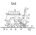
- the pallet-carrying truck 16 shown in Figure 2 consists of a body 35 mounted on pairs of wheels 36 and 37.
- the pair of wheels 36 is operationally connected to a steering device 38, whereas the pair of wheels 37 is operationally connected to an electric motor 39 by way of a transmission 40.
- the reference numeral 41 indicates a pallet supported by the truck 16, and 42 indicates a workpiece which is to be machined by one or all the machine tools 11, 12, 13 shown in Figure 1.
- the reference numeral 43 indicates a receiver for the command signals originating from the transmitter 33 of Figure 1.
- a battery bank 44 In the truck body 3 5 there are disposed a battery bank 44, a decoding centre 45 and a low-frequency pulsating electric current generator indicated by 46.
- the centre 45 is operationally connected by the lines 47, 48, 49, 50, 51 to the receiver 43, the battery 44, the electric motor 39, the generator 46 and the steering device 38 respectively.
- the generator 46 is also connected by the conductors 52 and 53 to the electromagnets 19 and 20.
- the position of a truck, for example the truck 16, within the area 10 is determined as a result of the energisation of its electromagnets 19 and 20, to which the generator 46 feeds a current pulsating at a prechosen frequency.
- the electromagnets when the electromagnets are energised they induce a pulsating voltage in the electrical conductors 24 and 25 situated around them.
- the signals originating from the conductors 24 and 25 enter the interface 26 where they are selected by a multiplexer and then fed in sequence to the computer 29 through the lines 27 and 28.
- the computer executes a processing program which calculates the mean value of the pulsating signals orginating from the conductors 24 and 25 and compares the mean value of the signals with a predetermined threshold value. This enables the signals emitted by the conductors closest to the electromagnets 19 and 2C to be identified.
- the aforesaid processing operations could also be performed by an auxiliary microcomputer disposed downstream of the multiplexer in the interface 26.
- the computer continuing to execute its operating program, then statistically programs the thus discriminated signals and calculates the maximum of the signal distribution curve or compares the absolute values of the signals in order to determine the maximum value, which pertains to the conductor closest to the electromagnet.
- the computer determines that an electromagnet position is equidistant from the said two conductors 24 or 25.
- the computer is thus able to identify the pairs of conductors 24 and 25 which intersect at the point closest to the electromagnets 19 and 20 of the truck 16, and consequently is able to determine the coordinates of the position of the electromagnets, from which the location and orientation of the truck 16 within the area 10 can be obtained.
- the computer 29 establishes the operation scheduled for the workpiece 42 carried by the truck 16 in the particular stage of the relative machining cycle, and identifies the machine tool which has to be reached by this truck. With this information, and on the basis of the data contained in the memory section 30, the computer is able to define with reference to the
- map of the working area the most convenient path to enable the truck 16 to reach the determined working station.
- the computer 29 then establishes the types of commands necessary for making the truck 16 undergo the determined path.
- the system can be rapidly adapted to changed production conditions, even if changing to other types of workpieces to be produced, it being necessary only to modify the data contained in the memory section 31 relative to the machining cycles and the data contained in the memory section 30 relative to the map of the working area.
- the truck 16 shown in Figure 3 differs from that shown in Figure 2 only in that the receiver 43 is absent, but instead a sensor 55 is provided which enables it to pick up the command signals when fed by the computer 29 through the conductors 24 and 25, it being connected to the centre 45 by the line 56.
Landscapes
- Engineering & Computer Science (AREA)
- Mechanical Engineering (AREA)
- Physics & Mathematics (AREA)
- Electromagnetism (AREA)
- Heart & Thoracic Surgery (AREA)
- Health & Medical Sciences (AREA)
- Transportation (AREA)
- Aviation & Aerospace Engineering (AREA)
- Radar, Positioning & Navigation (AREA)
- Remote Sensing (AREA)
- General Physics & Mathematics (AREA)
- Automation & Control Theory (AREA)
- Multi-Process Working Machines And Systems (AREA)
Applications Claiming Priority (2)
| Application Number | Priority Date | Filing Date | Title |
|---|---|---|---|
| IT22895/84A IT1176849B (it) | 1984-09-28 | 1984-09-28 | Impianto per la movimentazione di carrelli portapallets |
| IT2289584 | 1984-09-28 |
Publications (1)
| Publication Number | Publication Date |
|---|---|
| EP0176158A1 true EP0176158A1 (de) | 1986-04-02 |
Family
ID=11201638
Family Applications (1)
| Application Number | Title | Priority Date | Filing Date |
|---|---|---|---|
| EP85201524A Withdrawn EP0176158A1 (de) | 1984-09-28 | 1985-09-23 | System für die Steuerung von palettentragenden Wagen |
Country Status (2)
| Country | Link |
|---|---|
| EP (1) | EP0176158A1 (de) |
| IT (1) | IT1176849B (de) |
Cited By (8)
| Publication number | Priority date | Publication date | Assignee | Title |
|---|---|---|---|---|
| DE3614165A1 (de) * | 1986-04-26 | 1987-10-29 | Kloeckner Humboldt Deutz Ag | Transportsystem fuer serienfertigungen |
| EP0349852A3 (en) * | 1988-07-05 | 1990-06-13 | Cerit Spa | Method for the automatic feed of combing machines |
| WO1993022754A1 (en) * | 1992-05-01 | 1993-11-11 | Multilop Limited | Tracking system |
| EP0701881A1 (de) * | 1994-09-11 | 1996-03-20 | A RÖMHELD GmbH & CO KG | Bearbeitungssystem |
| GB2314171A (en) * | 1996-06-14 | 1997-12-17 | Post Office | Automated portering system |
| RU2159695C2 (ru) * | 1998-06-15 | 2000-11-27 | Царев Анатолий Михайлович | Способ смены и транспортирования многоинструментальных узлов в автоматической линии и автоматическая линия для его реализации |
| WO2013083144A1 (de) * | 2011-12-09 | 2013-06-13 | Daimler Ag | Verfahren zum betreiben einer produktionsanlage |
| EP3746262B1 (de) | 2018-08-30 | 2021-06-30 | DECKEL MAHO Pfronten GmbH | Transporteinrichtung zum transportieren einer oder mehrerer handhabungseinrichtungen |
Citations (5)
| Publication number | Priority date | Publication date | Assignee | Title |
|---|---|---|---|---|
| US3909922A (en) * | 1972-08-01 | 1975-10-07 | Toyoda Machine Works Ltd | Control system for plural numerically controlled machine tools |
| GB2045463A (en) * | 1979-04-03 | 1980-10-29 | Hall Automation Ltd | Arrangement for controlling an operation performed on a workpiece |
| EP0109201A2 (de) * | 1982-10-19 | 1984-05-23 | Calspan Corporation | Selbstfahrende Roboterplattform und System sowie Verfahren zum Bewegen eines Werkzeuges über eine Unterlage |
| DE3246828A1 (de) * | 1982-12-17 | 1984-06-20 | Fraunhofer-Gesellschaft zur Förderung der angewandten Forschung e.V., 8000 München | Mobile transport- und handhabungseinrichtung |
| EP0043208B1 (de) * | 1980-06-18 | 1986-09-03 | Hitachi, Ltd. | Bearbeitungs- und Montagesystem |
-
1984
- 1984-09-28 IT IT22895/84A patent/IT1176849B/it active
-
1985
- 1985-09-23 EP EP85201524A patent/EP0176158A1/de not_active Withdrawn
Patent Citations (5)
| Publication number | Priority date | Publication date | Assignee | Title |
|---|---|---|---|---|
| US3909922A (en) * | 1972-08-01 | 1975-10-07 | Toyoda Machine Works Ltd | Control system for plural numerically controlled machine tools |
| GB2045463A (en) * | 1979-04-03 | 1980-10-29 | Hall Automation Ltd | Arrangement for controlling an operation performed on a workpiece |
| EP0043208B1 (de) * | 1980-06-18 | 1986-09-03 | Hitachi, Ltd. | Bearbeitungs- und Montagesystem |
| EP0109201A2 (de) * | 1982-10-19 | 1984-05-23 | Calspan Corporation | Selbstfahrende Roboterplattform und System sowie Verfahren zum Bewegen eines Werkzeuges über eine Unterlage |
| DE3246828A1 (de) * | 1982-12-17 | 1984-06-20 | Fraunhofer-Gesellschaft zur Förderung der angewandten Forschung e.V., 8000 München | Mobile transport- und handhabungseinrichtung |
Cited By (10)
| Publication number | Priority date | Publication date | Assignee | Title |
|---|---|---|---|---|
| DE3614165A1 (de) * | 1986-04-26 | 1987-10-29 | Kloeckner Humboldt Deutz Ag | Transportsystem fuer serienfertigungen |
| EP0349852A3 (en) * | 1988-07-05 | 1990-06-13 | Cerit Spa | Method for the automatic feed of combing machines |
| EP0663463A1 (de) * | 1988-07-05 | 1995-07-19 | Maschinenfabrik Rieter Ag | Transporteinrichtung für Wattewickel und leere Hülsen |
| WO1993022754A1 (en) * | 1992-05-01 | 1993-11-11 | Multilop Limited | Tracking system |
| EP0701881A1 (de) * | 1994-09-11 | 1996-03-20 | A RÖMHELD GmbH & CO KG | Bearbeitungssystem |
| GB2314171A (en) * | 1996-06-14 | 1997-12-17 | Post Office | Automated portering system |
| EP0812628A3 (de) * | 1996-06-14 | 1999-05-06 | The Post Office | Automatisiertes Fördersystem |
| RU2159695C2 (ru) * | 1998-06-15 | 2000-11-27 | Царев Анатолий Михайлович | Способ смены и транспортирования многоинструментальных узлов в автоматической линии и автоматическая линия для его реализации |
| WO2013083144A1 (de) * | 2011-12-09 | 2013-06-13 | Daimler Ag | Verfahren zum betreiben einer produktionsanlage |
| EP3746262B1 (de) | 2018-08-30 | 2021-06-30 | DECKEL MAHO Pfronten GmbH | Transporteinrichtung zum transportieren einer oder mehrerer handhabungseinrichtungen |
Also Published As
| Publication number | Publication date |
|---|---|
| IT8422895A0 (it) | 1984-09-28 |
| IT1176849B (it) | 1987-08-18 |
Similar Documents
| Publication | Publication Date | Title |
|---|---|---|
| US20240149451A1 (en) | Systems and methods for process tending with a robot arm | |
| EP0304942B1 (de) | Produktionssystem mit unbemannten, automatisch geführten Fahrzeugen | |
| US8157155B2 (en) | Automated assembly and welding of structures | |
| US4993507A (en) | Method of controlling operation of automated guided vehicle | |
| CN107229281B (zh) | 一种agv小车的导引方法、智能制造生产线以及物流系统 | |
| CN107405736B (zh) | 制造装置、制造设备和方法 | |
| US12296470B2 (en) | Autonomous mobile vehicle | |
| EP0176158A1 (de) | System für die Steuerung von palettentragenden Wagen | |
| Zhao et al. | Autonomous mobile robots in manufacturing operations | |
| CN108147321B (zh) | 使搬运车自动定向的方法以及包括搬运车和货仓的系统 | |
| KR830006723A (ko) | 다목적 제조 시스팀 | |
| KR0123809B1 (ko) | 차량 제어 및 유도 시스템과 그 작동 방법 | |
| Vosniakos et al. | Automated guided vehicle system design for FMS applications | |
| KR102804919B1 (ko) | 무지향성 경유지점을 이용한 자율이동로봇 및 그 제어 방법 | |
| KR20150133493A (ko) | 공작기계용 공작물 인식 장치 | |
| US20240408713A1 (en) | Method for assignng an emergency-stop functionality, and automation system | |
| CN108287520A (zh) | 一种汽车锻造轮毂柔性上下料自动生产线 | |
| JP2019120992A (ja) | Agv制御システム | |
| JPH04141350A (ja) | 加工システムの搬送車制御方法及び装置 | |
| Tung et al. | Implementation of Multi-process automatic Loading and Unloading production system | |
| Nayak et al. | Conceptual development of an adaptive real-time seam tracker for welding automation | |
| JPH02198749A (ja) | 生産情報転送装置 | |
| CN207799451U (zh) | 一种汽车锻造轮毂柔性上下料自动生产线 | |
| KR102704172B1 (ko) | 중전력 로봇 무선충전 시스템 | |
| EP0297143A1 (de) | Anordnung zur führung einer sich bewegenden roboters |
Legal Events
| Date | Code | Title | Description |
|---|---|---|---|
| PUAI | Public reference made under article 153(3) epc to a published international application that has entered the european phase |
Free format text: ORIGINAL CODE: 0009012 |
|
| AK | Designated contracting states |
Kind code of ref document: A1 Designated state(s): DE FR GB |
|
| 17P | Request for examination filed |
Effective date: 19860613 |
|
| RAP1 | Party data changed (applicant data changed or rights of an application transferred) |
Owner name: ALFA LANCIA INDUSTRIALE S.R.L. |
|
| 17Q | First examination report despatched |
Effective date: 19870827 |
|
| RAP1 | Party data changed (applicant data changed or rights of an application transferred) |
Owner name: ALFA LANCIA INDUSTRIALE S.P.A. |
|
| STAA | Information on the status of an ep patent application or granted ep patent |
Free format text: STATUS: THE APPLICATION IS DEEMED TO BE WITHDRAWN |
|
| 18D | Application deemed to be withdrawn |
Effective date: 19890404 |
|
| RIN1 | Information on inventor provided before grant (corrected) |
Inventor name: BASSI, ALDO |