EP0176175A2 - Fabrication de gaines thermo-rétractables en utilisant un moyen solide - Google Patents
Fabrication de gaines thermo-rétractables en utilisant un moyen solide Download PDFInfo
- Publication number
- EP0176175A2 EP0176175A2 EP85304584A EP85304584A EP0176175A2 EP 0176175 A2 EP0176175 A2 EP 0176175A2 EP 85304584 A EP85304584 A EP 85304584A EP 85304584 A EP85304584 A EP 85304584A EP 0176175 A2 EP0176175 A2 EP 0176175A2
- Authority
- EP
- European Patent Office
- Prior art keywords
- sleeve
- core
- compound
- inchoate
- crosshead
- Prior art date
- Legal status (The legal status is an assumption and is not a legal conclusion. Google has not performed a legal analysis and makes no representation as to the accuracy of the status listed.)
- Withdrawn
Links
- 238000004519 manufacturing process Methods 0.000 title claims description 18
- 239000007787 solid Substances 0.000 title description 2
- 150000001875 compounds Chemical class 0.000 claims abstract description 68
- 238000000034 method Methods 0.000 claims abstract description 44
- 239000012530 fluid Substances 0.000 claims abstract description 38
- IJGRMHOSHXDMSA-UHFFFAOYSA-N Atomic nitrogen Chemical compound N#N IJGRMHOSHXDMSA-UHFFFAOYSA-N 0.000 claims abstract description 22
- 238000011144 upstream manufacturing Methods 0.000 claims abstract description 22
- 229910052757 nitrogen Inorganic materials 0.000 claims abstract description 11
- 239000007788 liquid Substances 0.000 claims abstract description 10
- 238000001816 cooling Methods 0.000 claims description 13
- 239000007789 gas Substances 0.000 claims description 10
- 230000000694 effects Effects 0.000 claims description 8
- 239000000463 material Substances 0.000 claims description 8
- 239000002131 composite material Substances 0.000 claims description 5
- 238000003466 welding Methods 0.000 claims description 5
- 238000010438 heat treatment Methods 0.000 claims description 3
- 238000004804 winding Methods 0.000 claims description 3
- 229920001187 thermosetting polymer Polymers 0.000 claims 2
- 230000008569 process Effects 0.000 abstract description 16
- 238000009413 insulation Methods 0.000 description 23
- 238000001125 extrusion Methods 0.000 description 13
- AVYVHIKSFXVDBG-UHFFFAOYSA-N N-benzyl-N-hydroxy-2,2-dimethylbutanamide Chemical compound C(C1=CC=CC=C1)N(C(C(CC)(C)C)=O)O AVYVHIKSFXVDBG-UHFFFAOYSA-N 0.000 description 7
- 239000011230 binding agent Substances 0.000 description 6
- 239000004020 conductor Substances 0.000 description 4
- 239000002245 particle Substances 0.000 description 4
- 230000004048 modification Effects 0.000 description 3
- 238000012986 modification Methods 0.000 description 3
- 229910052782 aluminium Inorganic materials 0.000 description 2
- XAGFODPZIPBFFR-UHFFFAOYSA-N aluminium Chemical compound [Al] XAGFODPZIPBFFR-UHFFFAOYSA-N 0.000 description 2
- 230000015556 catabolic process Effects 0.000 description 2
- 238000005520 cutting process Methods 0.000 description 2
- 238000005304 joining Methods 0.000 description 2
- 229920000642 polymer Polymers 0.000 description 2
- 239000004065 semiconductor Substances 0.000 description 2
- 230000015572 biosynthetic process Effects 0.000 description 1
- 238000004891 communication Methods 0.000 description 1
- 238000010276 construction Methods 0.000 description 1
- 238000010924 continuous production Methods 0.000 description 1
- 238000004132 cross linking Methods 0.000 description 1
- 230000007547 defect Effects 0.000 description 1
- 230000001627 detrimental effect Effects 0.000 description 1
- 230000008030 elimination Effects 0.000 description 1
- 238000003379 elimination reaction Methods 0.000 description 1
- 230000008020 evaporation Effects 0.000 description 1
- 238000001704 evaporation Methods 0.000 description 1
- 238000007710 freezing Methods 0.000 description 1
- 230000008014 freezing Effects 0.000 description 1
- 230000006872 improvement Effects 0.000 description 1
- 238000007373 indentation Methods 0.000 description 1
- 239000011810 insulating material Substances 0.000 description 1
- 238000003754 machining Methods 0.000 description 1
- 229910052751 metal Inorganic materials 0.000 description 1
- 239000002184 metal Substances 0.000 description 1
- 239000000203 mixture Substances 0.000 description 1
- 230000002028 premature Effects 0.000 description 1
- 238000003825 pressing Methods 0.000 description 1
- 230000009467 reduction Effects 0.000 description 1
- 229920002994 synthetic fiber Polymers 0.000 description 1
Images


Classifications
-
- B—PERFORMING OPERATIONS; TRANSPORTING
- B29—WORKING OF PLASTICS; WORKING OF SUBSTANCES IN A PLASTIC STATE IN GENERAL
- B29C—SHAPING OR JOINING OF PLASTICS; SHAPING OF MATERIAL IN A PLASTIC STATE, NOT OTHERWISE PROVIDED FOR; AFTER-TREATMENT OF THE SHAPED PRODUCTS, e.g. REPAIRING
- B29C49/00—Blow-moulding, i.e. blowing a preform or parison to a desired shape within a mould; Apparatus therefor
- B29C49/42—Component parts, details or accessories; Auxiliary operations
- B29C49/58—Blowing means
-
- B—PERFORMING OPERATIONS; TRANSPORTING
- B29—WORKING OF PLASTICS; WORKING OF SUBSTANCES IN A PLASTIC STATE IN GENERAL
- B29C—SHAPING OR JOINING OF PLASTICS; SHAPING OF MATERIAL IN A PLASTIC STATE, NOT OTHERWISE PROVIDED FOR; AFTER-TREATMENT OF THE SHAPED PRODUCTS, e.g. REPAIRING
- B29C48/00—Extrusion moulding, i.e. expressing the moulding material through a die or nozzle which imparts the desired form; Apparatus therefor
- B29C48/03—Extrusion moulding, i.e. expressing the moulding material through a die or nozzle which imparts the desired form; Apparatus therefor characterised by the shape of the extruded material at extrusion
- B29C48/06—Rod-shaped
-
- B—PERFORMING OPERATIONS; TRANSPORTING
- B29—WORKING OF PLASTICS; WORKING OF SUBSTANCES IN A PLASTIC STATE IN GENERAL
- B29C—SHAPING OR JOINING OF PLASTICS; SHAPING OF MATERIAL IN A PLASTIC STATE, NOT OTHERWISE PROVIDED FOR; AFTER-TREATMENT OF THE SHAPED PRODUCTS, e.g. REPAIRING
- B29C48/00—Extrusion moulding, i.e. expressing the moulding material through a die or nozzle which imparts the desired form; Apparatus therefor
- B29C48/15—Extrusion moulding, i.e. expressing the moulding material through a die or nozzle which imparts the desired form; Apparatus therefor incorporating preformed parts or layers, e.g. extrusion moulding around inserts
-
- B—PERFORMING OPERATIONS; TRANSPORTING
- B29—WORKING OF PLASTICS; WORKING OF SUBSTANCES IN A PLASTIC STATE IN GENERAL
- B29C—SHAPING OR JOINING OF PLASTICS; SHAPING OF MATERIAL IN A PLASTIC STATE, NOT OTHERWISE PROVIDED FOR; AFTER-TREATMENT OF THE SHAPED PRODUCTS, e.g. REPAIRING
- B29C49/00—Blow-moulding, i.e. blowing a preform or parison to a desired shape within a mould; Apparatus therefor
- B29C49/0015—Making articles of indefinite length, e.g. corrugated tubes
-
- B—PERFORMING OPERATIONS; TRANSPORTING
- B29—WORKING OF PLASTICS; WORKING OF SUBSTANCES IN A PLASTIC STATE IN GENERAL
- B29C—SHAPING OR JOINING OF PLASTICS; SHAPING OF MATERIAL IN A PLASTIC STATE, NOT OTHERWISE PROVIDED FOR; AFTER-TREATMENT OF THE SHAPED PRODUCTS, e.g. REPAIRING
- B29C61/00—Shaping by liberation of internal stresses; Making preforms having internal stresses; Apparatus therefor
- B29C61/06—Making preforms having internal stresses, e.g. plastic memory
- B29C61/08—Making preforms having internal stresses, e.g. plastic memory by stretching tubes
-
- H—ELECTRICITY
- H02—GENERATION; CONVERSION OR DISTRIBUTION OF ELECTRIC POWER
- H02G—INSTALLATION OF ELECTRIC CABLES OR LINES, OR OF COMBINED OPTICAL AND ELECTRIC CABLES OR LINES
- H02G15/00—Cable fittings
- H02G15/08—Cable junctions
- H02G15/18—Cable junctions protected by sleeves, e.g. for communication cable
- H02G15/1806—Heat shrinkable sleeves
-
- B—PERFORMING OPERATIONS; TRANSPORTING
- B29—WORKING OF PLASTICS; WORKING OF SUBSTANCES IN A PLASTIC STATE IN GENERAL
- B29L—INDEXING SCHEME ASSOCIATED WITH SUBCLASS B29C, RELATING TO PARTICULAR ARTICLES
- B29L2031/00—Other particular articles
- B29L2031/34—Electrical apparatus, e.g. sparking plugs or parts thereof
- B29L2031/3412—Insulators
Definitions
- This invention relates to heat-shrinkable sleeves for use in splicing electrical cables and the like and, more particularly, to a novel and highly-effective method and apparatus for manufacturing such sleeves, and to sleeves made by the method and apparatus.
- U.S. Patent No. 4,446,095 issued 1st May 1984, on an invention of Katz and Zidon, discloses the most efficient method of manufacturing long lengths of heat-shrinkable sleeves heretofore known.
- a sleeve is formed around a permeable core, and the core and sleeve are advanced together in an axial direction, the leading end of the advancing sleeve being hermetically sealed.
- the core and sleeve pass through a heating station, thereby heating a portion of at least the sleeve, and a fluid is introduced under pressure into the core, thereby internally pressurizing the sleeve to effect a radial expansion of the heated portion thereof.
- the core and sleeve then pass through a cooling station, thereby cooling the expanded sleeve to stabilize it.
- the core is removed from the sleeve, and the sleeve is cut to suitable lengths which are used to join electrical cables and the like.
- the sleeves When the sleeves are heated on site, they shrink around the cable ends and help to form a permanent splice.
- binders or tapes are applied over the permeable core.
- the binders are preferably of a high temperature resistant film or paper. The binders are removed from the sleeve together with the metallic core before the sleeve is used in joining or splicing cables.
- the problem is exacerbated by the tendency of the compound to work its way between adjacent layers of the binder under the high pressures employed in the process of manufacturing the sleeve.
- the irregularities or discontinuities of the inner surface of the sleeve can give rise to cracks in the sleeve when it is expanded.
- some additional processing (machining) is required before the sleeves can be utilized.
- An object of the invention is to make a further advance in the art of manufacturing long lengths of a heat-shrinkable sleeve for use in splicing electrical cables and the like.
- an object of the invention is to provide a method and apparatus for manufacturing a heat-shrinkable sleeve having a perfectly smooth interior surface.
- Another object of the invention is to provide a method and apparatus for manufacturing a heat-shrinkable sleeve wherein the overall insulation wall thickness is reduced.
- Still another object of the invention is to provide a method and apparatus for manufacturing a heat-shrinkable sleeve which is built up in a plurality of layers in a single continuous process in such a manner that an outer layer can be extruded around an inner layer without deforming the latter or otherwise causing damage.
- an elongated impermeable core having a smooth outer surface
- extruding an elongated sleeve around and in contact with the core the sleeve having a smooth inner surface conforming to the outer surface of the core, and effecting an expansion of a portion of the sleeve to a larger diameter in an expansion zone so that the sleeve separates from the core and leaves a space between the sleeve and core.
- a fluid is introduced into the space between the sleeve and core under pressure while continuously advancing the sleeve and core through the expansion zone. In this manner, successive portions of the sleeve are expanded by the fluid as they advance through the zone.
- an elongated permeable core is provided, and a sleeve is extruded around and in contact with the permeable core.
- the leading end of the sleeve is provided with a sealed fitting, and fluid is introduced under pressure through the fitting and permeable core to the inside of the sleeve in the expansion zone.
- the leading end of the impermeable core is welded to the trailing end of the permeable core at a location upstream of the expansion zone.
- the sleeve has a composite structure comprising an inner compound and an outer compound, the inner and outer compounds having different characteristics.
- a first crosshead is provided having a tip, an intermediate aperture radially outward and downstream of the tip, and a die radially outward and downstream of the intermediate aperture.
- the core (whether permeable or impermeable) is passed through the tip, the inner compound is extruded between the tip and intermediate aperture, and the outer compound is extruded between the intermediate aperture and the die.
- the intermediate aperture thus functions as a die for the inner compound and as a tip for the outer compound, whereby an inchoate sleeve is formed around the core.
- the core and, inchoate sleeve are passed through a second crosshead, and an additional quantity of the outer compound is extruded around the inchoate sleeve within the second crosshead.
- An insulation shield may be applied over the insulation by a final extruder in the second crosshead.
- the inchoate sleeve is cooled between the first and second crossheads.
- the cooling is preferably accomplished by liquid nitrogen.
- Figure 1A shows protrusions caused by hard conducting particles in accordance with processes of the prior art.
- a core 10 has a layer 12 of semiconducting compound extruded around and in contact with the core 10.
- the core 10 is permeable and may, for example, be a stranded conductor.
- Hard particles incorporated in the semiconducting compound forming the layer 12 may pop up when the layer 12 leaves the die of,the upstream crosshead, resulting in protrusions 14 into the layer 16 of insulating compound.
- Fig. 1B shows die bleed lumps or masses 18 on the surface of the semiconducting layer 12.
- Die bleed is a small deposit of semiconducting compound accumulated on the outer surfaces of the crosshead die. The accumulated compound occasionally works loose and becomes deposited on the outer surface of the inner layer 12. Since this compound is semiconducting, it is tantamount to protrusions of semiconductor into the insulation 16, which give rise to high voltage stresses conducive to premature breakdown of the sleeve.
- Fig. 1C shows push-back irregularities 20 due to heavy thickness of the inner layer 12 and high pressures employed during the extrusion of the insulation 16.
- the pressures tend to push back the inner layer 12.
- the effect is somewhat significant when the inner layer 12 is thin, as illustrated in Fig. 1D, and very significant when the pressures are high and the inner layer 12 is relatively thick, as illustrated in Fig. lE.
- Figs. 1D and lE show a tip 20 and die 22 of a downstream crosshead employed in the prior art.
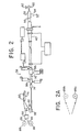
- Fig. 2 shows apparatus in accordance with the present invention for avoiding the problems of the prior art outlined above.
- a part of Fig. 2 is the same as apparatus disclosed in said Patent No. 4,446,095 and therefore is not described herein.
- the disclosure of that patent is incorporated herein by reference.
- the apparatus of the present invention manufactures long lengths of a heat-shrinkable sleeve 24 (Figs. 4 and 5) for use in splicing or joining electrical cables and the like.
- the method comprises providing an elongated impermeable core 26 (Fig. 5) having a smooth outer surface (Figs. 3A and 5).
- the impermeable or solid core 26 has a smooth skin 28 of cylindrical cross section enclosing a plurality of strands 30 arranged in four quadrants 32 defined by a vertical plane 34 and a horizontal plane 36.
- a smooth skin 28' encloses strands 30' which have a somewhat larger diameter than the strands 30 and are arranged in concentric circles. Both forms of core are conventional per se.
- the use of stranded wires 30 or 30' covered by an extruded or drawn tube of aluminum or other metal helps to maintain the flexibility of the core 26 or 26', so that the core is suitable for winding on a payoff or take-up reel.
- the core may also be made of a synthetic material. In any case, the extreme downstream end of the core should be sealed to prevent the loss of fluid through the core interior.
- Extrusion means indicated generally at 38 is provided for extruding the elongated sleeve 24 (Fig. 5) around and in contact with the core 26.
- the sleeve 24 has a smooth inner surface conforming to the outer surface of the core 26.
- a portion of the sleeve 24 is heated and expanded to a larger diameter in an expansion zone 40 (Figs. 2 and 5) so that the sleeve 24 separates from the core 26 and leaves a space 42 between the sleeve 24 and core 26.
- a fluid is introduced into the space 42 under pressure while continually advancing the sleeve 24 and core 26 through the expansion zone 40. Successive portions of the sleeve 24 are thus expanded by the fluid as they advance through the expansion zone 40.
- the impermeable core 26 is formed with a leading end 44, and the effecting of the initial expansion of the sleeve 24 preferably comprises the following steps performed before the leading end 44 of the impermeable core 26 reaches the expansion zone 40.
- an elongated permeable core 46 is provided, the permeable core 46 having a trailing end 48.
- the extrusion means 38 (Fig. 2) extrudes the sleeve 24 around and in contact with the permeable core 46, and fluid is introduced under pressure through the permeable core 46 to the inside of the sleeve 24 in the expansion zone 40.
- a welding unit 50 (Fig. 2) forms a connection of the leading end 44 of the impermeable core 26 to the trailing end 48 of the permeable core 46 at a location upstream of the expansion zone 40.
- fluid preferably pressurized gas
- Fig. 4 shows a fitting 52 adapted to this purpose. It comprises a generally cylindrical portion 54 open at one end 56 to accommodate the sleeve 24 and having a hemispherical structure 58 at the other end adapted to accommodate a valve 60 having a manual or other control member 62.
- the valve 60 admits a fluid such as a pressurized gas by means of a fitting 64 which penetrates an aperture 66 in the hemispherical portion 58, thus admitting the pressurized gas to the interior of the fitting 52 when the valve 60 is open.
- the fitting 52 is formed with grooves 68 which extend circumferentially of the fitting 52 and deform the leading end 70 of the sleeve 24 which is inserted into the fitting 52.
- An O-ring 72 is inserted on the inside of the fitting 52 and around the outside of the sleeve 24 longitudinally at a position between the grooves 68 in order to form a fluid-tight seal around the end 70 of the sleeve 24.
- the fitting 52 is conveniently connected to the end 70 of the sleeve 24 which is wound on a take-up reel (not shown).
- the pressurized gas admitted into the fitting 52 is admitted also into the interior of the sleeve 54 through the open end 70 thereof.
- This pressurized gas is in communication with the space 42 (Fig. 5) in the expansion zone 40 (which may be a considerable distance away), so that, after the impermeable core 26 arrives at the expansion zone 40, the sleeve 24 nevertheless continues to expand as successive portions thereof pass through the expansion zone 40.
- the expansion fluid in one embodiment of the invention is introduced into the space 42 via a fitting 74 (Fig. 2) upstream of the expansion zone 40.
- the fitting 74 and associated structure serves as a source of fluid under pressure and may be similar to the structure 136, 138 and associated structure shown in Fig. 5 of said patent identified above.
- the structure 74 may be dispensed with, and the expansion may be brought about from the very beginning by pressurized fluid (preferably gas) introduced through the fitting 52.
- pressurized fluid preferably gas
- an accumulator 76 (Fig. 2) is provided in accordance with the invention.
- the structural details of the accumulator 76 are immaterial so long as the accumulator 76 permits a metering capstan 78 to continue to feed the permeable core 46 to the extrusion means 38 so that the sleeve 24 can continue to be formed.
- the accumulator 76 may comprise rollers $0, at least one of the rollers being movably mounted in such a manner as to permit a variable length of the core 46 to be accommodated.
- the metering capstan 78 is also of conventional construction and may include a motor 82 and a belt or other driving connection 84 for turning the capstan 78.
- Two supply reels or payoff reels 86 and 88 are provided for supplying the permeable core 46 and impermeable core 26, respectively.
- the permeable core 46 is initially supplied first to the accumulator 76, then around the metering capstan 78, to the extrusion means 38, and the apparatus downstream thereof. After the trailing end 48 of the permeable core 46 is welded automatically or manually at the welding station 50 to the leading end 44 of the impermeable core 26, the accumulator 76 can in principle be bypassed, since it is no longer needed.
- the core 46 has already been threaded through the accumulator 76 and since the core 26 is now welded to the core 46, it is preferable to allow the core 26 to be threaded through the accumulator 76 en route to the metering capstan 78 and the apparatus downstream thereof.
- the outside diameter of the impermeable core 26 is limited to a value substantially equal to the outside diameter of the permeable core 46 so that the core 26 follows the core 46 without becoming snagged on the component 38, and components downstream thereof.
- the perforations are covered by a layer of material, such as paper, which prevents the flow of the first layer of compound into the holes.
- the perforations are of very small diameter but large in number and cover a distance of several meters. Perforations are made only when it becomes necessary to switch take-up reels. The location of the perforations is calculated in accordance with the particular characteristics of the extrusion process.
- perforations are made at such a time as to ensure that they will be in the cooled part of the expansion section at the time the switch-over cut is made.
- a section of the expanded sleeve Prior to cutting, a section of the expanded sleeve is shrunk down onto the core (while moving towards the take-up reel). This is easily accomplished by the application of heat, since the sleeve is heat-shrinkable. Pressure is removed for a short time to allow for cutting the sleeve.
- a new pressurizing fitting is applied at the end of the new length, and fluid pressure is applied.
- the perforations previously made in the core allow the fluid to escape from the core and enter the space 42 to restart the expansion process in the new section of sleeve emerging from the curing pipe. In this manner, no interruption in the extrusion process is required.
- the heat-shrinkable sleeve has a composite structure comprising an inner compound and an outer compound, the inner and outer compounds having different characteristics.
- Fig. 5 shows an inner compound 90 forming a semiconducting layer and an outer compound 92 forming an insulating layer.
- a semiconducting insulation shield 93 may also be provided.
- the extrusion means 38 shown schematically in Fig. 2 applies these three compounds in four extrusion steps.
- One of the novel features of the invention is the use of two insulation layers to obtain a higher breakdown strength.
- the extrusion means 38 comprises an upstream crosshead 38a and downstream crosshead 38b.
- Fig. 6 is a longitudinal sectional view through the first or upstream crosshead 38a.
- This first crosshead 38a comprises a tip 94, an intermediate aperture 96 radially outward and downstream of the tip 94 and a die 98 radially outward and downstream of the intermediate aperture 96.
- the core 46 (and subsequently the core 26) is passed through the tip 94, and the inner compound 90 is extruded between the tip 94 and intermediate aperture 96.
- a first layer 92a of the outer compound 92 is extruded between the intermediate aperture 96 and the die 98.
- the intermediate aperture 96 thus functions as a die for the inner compound 90 and as a tip for the outer compound 92.
- An inchoate sleeve is thus formed around the core 46 or 26.
- the inchoate sleeve is subsequently passed through the second or downstream crosshead 38b (Fig. 8), which applies an additional layer 92b of the outer compound 92 and the layer of insulation shield 93.
- This crosshead comprises a tip 104, an intermediate aperture 106 radially outward and downstream of the tip 104, and a die 108 radially outward and downstream of the intermediate aperture 106.
- the layer 92b is extruded between the tip 104 and intermediate aperture 106
- the layer 93 is extruded between the intermediate aperture 106 and the die 108.
- the intermediate aperture 106 functions as a die for the layer 92b and as a tip for the layer 93, thus completing the formation of the sleeve.
- a semiconducting compound is preferably selected as the inner compound 90 and an insulating compound is preferably selected as the outer compound 92, which forms the layers 92a and,92b.
- the extrusion of the layer 92a of insulating compound in the crosshead 38a permits a decrease in the overall thickness of the insulation required to support the operational voltage. This achievement is due to the elimination of sharp imperfections at the interface (see Figs. 1A through lE) which otherwise require an extra thickness of insulation to withstand the increased voltage stresses. A reduction of wall thickness in excess of 15% is achievable.
- the tip 104 of the extruder crosshead 38b (Fig. 8) has a very close tolerance (in diameter) with respect to the core with the inchoate sleeve thereon feeding to the crosshead 38b.
- This tolerance may be 0.0254 to 0.1016 cms in diameter, depending on the overall diameter of the core, and is required to avoid pushing the insulation compound backward.
- 1D and lE is somewhat significant when the inner layer is thin and very significant when the pressures are high and the inner layer is relatively thick.
- pressures are very high and result in surface irregularities detrimental to the integrity of the sleeve.
- the soft inner layer abrades against the tip, and irregularities in the form of additional protrusions, indentations, etc., occur. These irregularities result in voltage stress concentrations.
- the inner layer of the sleeve must be relatively thick because it is normal to expand the sleeve one to two times its original diameter.
- the application in the first crosshead 38a of a thin layer 92a of insulating compound having the same or similar insulating characteristics as those of the insulating layer or layers applied in the main, second or downstream crosshead 38b protects the semiconducting layer 90 against irregularities. Any irregularities caused upon entry into the second crosshead 38b occur in the insulating layer 92a which overlies and protects the layer 90. The integrity and smoothness of the inner semiconducting layer 90 are thus preserved.
- Irregularities on the surface of the auxiliary layer 92a of insulation are without importance, because upon application of additonal layer 92b of the same or similar material, the irregularities blend with the main insulation without causing points of high stress concentration.' Under the high pressures and crosslinking effects, an intimate bond occurs between the surface of the two insulating layers 92a and 92b of the compound 92. Since stress enhancement due to inner semiconducting layer irregularities is eliminated, a thinner overall insulating wall can be afforded.
- the layer 92a of insulating material applied in the upstream crosshead 38a does not need to be heavy. A thickness of 0.076 or preferably 0.1016 cms suffices for this purpose.
- the inside layer or layers of the composite inchoate sleeve are hardened before entering the second crosshead 38b.
- Said prior patent to Katz et al cited above discloses in Fig. 5 means 138, 140 for applying pressure from the outside on the enclosed space between the two crossheads.
- the internal layer or layers of compound are soft because of material characteristics and extrusion temperatures.
- the downstream crosshead 38b has very small tolerances with respect to the inchoate sleeve. Because of the softness of the compound and the relatively heavy thickness with which it needs to be extruded so that it can maintain its integrity and a certain minimum thickness when expanded several times its original diameter, this material tends to abrade against the walls of the opening through which it passes. The pressures on the insulation tend to cause the compound applied in the first crosshead 38a to bulge.
- the first section 111 is filled with liquid nitrogen and the second 112 is filled with pressurized gas at a higher temperature.
- a seal 113 prevents leakage between the two sections 111 and 112.
- liquid nitrogen additionally allows for increased line speed when the limiting factor is the softness of the compound entering the second crosshead 38b.
- the pressure in the downstream crosshead 38b caused bulging of the compound over the core to such a degree that the run had to be stopped.
- the run was continued without a problem. Subsequently, the speed was increased up to 20% without the same problem reappearing.
Landscapes
- Engineering & Computer Science (AREA)
- Mechanical Engineering (AREA)
- Manufacturing & Machinery (AREA)
- Shaping By String And By Release Of Stress In Plastics And The Like (AREA)
- Extrusion Moulding Of Plastics Or The Like (AREA)
- Lining Or Joining Of Plastics Or The Like (AREA)
- Mechanical Coupling Of Light Guides (AREA)
- Processing Of Terminals (AREA)
Applications Claiming Priority (2)
| Application Number | Priority Date | Filing Date | Title |
|---|---|---|---|
| US645013 | 1984-08-28 | ||
| US06/645,013 US4863541A (en) | 1984-08-28 | 1984-08-28 | Apparatus and method for manufacturing heat-shrinkable sleeve using solid core |
Publications (1)
| Publication Number | Publication Date |
|---|---|
| EP0176175A2 true EP0176175A2 (fr) | 1986-04-02 |
Family
ID=24587290
Family Applications (1)
| Application Number | Title | Priority Date | Filing Date |
|---|---|---|---|
| EP85304584A Withdrawn EP0176175A2 (fr) | 1984-08-28 | 1985-06-27 | Fabrication de gaines thermo-rétractables en utilisant un moyen solide |
Country Status (5)
| Country | Link |
|---|---|
| US (1) | US4863541A (fr) |
| EP (1) | EP0176175A2 (fr) |
| JP (1) | JPS6176346A (fr) |
| BR (1) | BR8503325A (fr) |
| ES (1) | ES8608389A1 (fr) |
Families Citing this family (10)
| Publication number | Priority date | Publication date | Assignee | Title |
|---|---|---|---|---|
| US4983333A (en) * | 1989-02-16 | 1991-01-08 | Siecor Corporation | Method for controlling excess fiber length in a loose tube optical fiber buffer tube |
| US4921413A (en) * | 1989-02-16 | 1990-05-01 | Siecor Corporation | Apparatus for controlling excess fiber length in a loose tube optical fiber buffer tube |
| US6090319A (en) * | 1997-01-14 | 2000-07-18 | Ticona Celstran, Inc. | Coated, long fiber reinforcing composite structure and process of preparation thereof |
| JP3054417B1 (ja) * | 1999-08-20 | 2000-06-19 | 住友大阪セメント株式会社 | 紙送りロ―ラの製造方法 |
| US20060210762A1 (en) * | 2005-03-17 | 2006-09-21 | Tachauer Ernesto S | Rigid subtrates having molded projections, and methods of making the same |
| US7794559B2 (en) | 2000-03-14 | 2010-09-14 | Velcro Industries B.V. | Forming fastening projections on rigid substrates |
| FR2811685B1 (fr) * | 2000-07-13 | 2002-10-25 | Imphy Ugine Precision | Procede de reglage de la resistance de contact de l'interface entre deux composants de pieces polymetalliques |
| US8678807B2 (en) * | 2000-10-24 | 2014-03-25 | Velcro Industries B.V. | Molding apparatus and related methods |
| DE60139516D1 (de) * | 2000-10-25 | 2009-09-17 | Velcro Ind | Verfahren zur kontinuierlichen Herstellung eines elektrischen Kabels |
| US8061886B1 (en) | 2008-04-30 | 2011-11-22 | Velcro Industries B.V. | Securing electrical devices |
Family Cites Families (2)
| Publication number | Priority date | Publication date | Assignee | Title |
|---|---|---|---|---|
| JPS6050132B2 (ja) * | 1981-07-17 | 1985-11-07 | 豊田合成株式会社 | 補強ホ−スの製造装置 |
| US4446095A (en) * | 1982-08-23 | 1984-05-01 | Cable Technology Laboratories, Inc. | Method for manufacturing heat shrinkable tubing |
-
1984
- 1984-08-28 US US06/645,013 patent/US4863541A/en not_active Expired - Fee Related
-
1985
- 1985-06-27 EP EP85304584A patent/EP0176175A2/fr not_active Withdrawn
- 1985-07-11 BR BR8503325A patent/BR8503325A/pt unknown
- 1985-07-16 ES ES545259A patent/ES8608389A1/es not_active Expired
- 1985-08-19 JP JP60181595A patent/JPS6176346A/ja active Pending
Also Published As
| Publication number | Publication date |
|---|---|
| JPS6176346A (ja) | 1986-04-18 |
| ES545259A0 (es) | 1986-06-16 |
| ES8608389A1 (es) | 1986-06-16 |
| US4863541A (en) | 1989-09-05 |
| BR8503325A (pt) | 1986-04-08 |
Similar Documents
| Publication | Publication Date | Title |
|---|---|---|
| US4863541A (en) | Apparatus and method for manufacturing heat-shrinkable sleeve using solid core | |
| US4099425A (en) | Method of making push-pull cable conduit and product | |
| KR940007857B1 (ko) | 드립 용수 도관의 제조 장치 및 방법 | |
| GB2105059A (en) | Optical fibre composite aerial cable | |
| NO850581L (no) | Undervannskabel | |
| CA2065074C (fr) | Cable de transfert d'electricite et methode de fabrication | |
| US6047586A (en) | Method for manufacturing a metal tube with at least one optical fiber therein | |
| US4446095A (en) | Method for manufacturing heat shrinkable tubing | |
| CA1089409A (fr) | Methode de fabrication de cables coaxiaux et appareil connexe | |
| US4305900A (en) | Method and apparatus for covering a multiple wire conductor with a cross-linkable or vulcanizable insulation | |
| US4482413A (en) | Methods of and apparatus for forming strips of non-metallic and metallic material into tubular covers having overlapped seams | |
| JPS61128418A (ja) | ケーブルコアの製造方法及び製造装置 | |
| US4623504A (en) | Method and apparatus for making post-tensioning tendons for concrete | |
| EP0326928A1 (fr) | Procédé et dispositif pour enrober par secteurs des objets avec de la matière plastique | |
| US4519759A (en) | Apparatus for making shrinkable tubing | |
| EP0252749B1 (fr) | Appareil pour la fabrication en continu de tubes en résine réticulée thermorétractables | |
| US3218207A (en) | Method of making leak-proof cable | |
| US4840552A (en) | Apparatus for continuously producing heat-shrinkable crosslinked resin tube | |
| KR20020061519A (ko) | 초전도 케이블 제조 방법 | |
| US2629921A (en) | Method of sheathing cable cores | |
| GB2093261A (en) | Electric cable | |
| JP2978104B2 (ja) | 自己支持型パイプ複合ケーブル | |
| WO1983000459A1 (fr) | Appareil d'extrusion et procedes d'epissage de cordes ou cables utilisant cet appareil | |
| JPH0351210B2 (fr) | ||
| SU1367104A1 (ru) | Способ изготовлени пазовых гильз |
Legal Events
| Date | Code | Title | Description |
|---|---|---|---|
| PUAI | Public reference made under article 153(3) epc to a published international application that has entered the european phase |
Free format text: ORIGINAL CODE: 0009012 |
|
| AK | Designated contracting states |
Kind code of ref document: A2 Designated state(s): BE DE FR GB IT LU NL SE |
|
| STAA | Information on the status of an ep patent application or granted ep patent |
Free format text: STATUS: THE APPLICATION IS DEEMED TO BE WITHDRAWN |
|
| 18D | Application deemed to be withdrawn |
Effective date: 19880405 |
|
| RIN1 | Information on inventor provided before grant (corrected) |
Inventor name: DIMA, ATTILA Inventor name: KATZ, CARLOS |