EP0176242A2 - Système compteur connecté en série - Google Patents
Système compteur connecté en série Download PDFInfo
- Publication number
- EP0176242A2 EP0176242A2 EP85306014A EP85306014A EP0176242A2 EP 0176242 A2 EP0176242 A2 EP 0176242A2 EP 85306014 A EP85306014 A EP 85306014A EP 85306014 A EP85306014 A EP 85306014A EP 0176242 A2 EP0176242 A2 EP 0176242A2
- Authority
- EP
- European Patent Office
- Prior art keywords
- scale
- center machine
- clerk
- text
- customer
- Prior art date
- Legal status (The legal status is an assumption and is not a legal conclusion. Google has not performed a legal analysis and makes no representation as to the accuracy of the status listed.)
- Granted
Links
Images




Classifications
-
- G—PHYSICS
- G01—MEASURING; TESTING
- G01G—WEIGHING
- G01G23/00—Auxiliary devices for weighing apparatus
- G01G23/18—Indicating devices, e.g. for remote indication; Recording devices; Scales, e.g. graduated
- G01G23/38—Recording and/or coding devices specially adapted for weighing apparatus
- G01G23/42—Recording and/or coding devices specially adapted for weighing apparatus electrically operated
-
- G—PHYSICS
- G07—CHECKING-DEVICES
- G07G—REGISTERING THE RECEIPT OF CASH, VALUABLES, OR TOKENS
- G07G1/00—Cash registers
- G07G1/12—Cash registers electronically operated
- G07G1/14—Systems including one or more distant stations co-operating with a central processing unit
Definitions
- the present invention relates to counting in-line system adopted in a super-market or the like.
- An object of the invention is to provide counting in-line system wherein the transaction data coming from the scale is controlled finely in the center machine so that the system becomes suited to each shop and easy for the use.
- the center machine and a plurality of scales are in-line connected, the centralized control of the transaction data per each counting article registered at the scale is performed in the center machine, and if the receipt issuing is requested from the scale side the print data is supplied from the center machine to the scale so as to issue the receipt, thereby the fine control of the transaction data and the arbitrary receipt issuing at the scale side can be performed and the system becomes suited to the shop and easy for the use.
- the transaction data is controlled in two independent numbers, the customer No. and the clerk No., processing corresponding to floating system and clerk fixed system can be performed.
- a clerk registers an article in each counter and a customer does not receive the article at each registering state.
- the customer total receipt is issued at any scale, the customer receives the articles together and the accounts are settled in the register based on the customer total receipt.
- both the customer No. and the clerk No. are inputted.
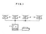
- Fig. 1 shows a system constitution, and a center machine 1 is in-line connected to scales 2 composed of #1 - #16.
- the center machine 1 may be ECR (cash register) for example.
- Each scale 2 has receipt issuing function, and appearance constitution thereof is as shown in Fig. 2.
- a scale body 3 is provided at upper side with a tray 4, and a weight measuring member 5 is formed.
- a thermal printer 6 is installed on one side of the scale body 3.
- a keyboard 7 with a number of keys arranged thereon is installed on front surface of the scale body 3.
- a receipt issuing port 8 is formed on front surface of the thermal printer 6.
- a zero switch 9 and a register mode changing switch 10 of key switch are installed at lower side of the front surface of the body 3.
- a strut 11 is installed on rear surface of the body 3, and an indicator 12 is mounted on the strut 11.
- a remote keyboard 13 is connected to side surface of the body 3.
- the keyboard 7 is provided with ten-keys 14 comprising numerals 0 - 9 and other various keys.
- Symbols 1 - 10 represent clerk keys 15 to assign clerk Nos. by DLL from side of the center machine 1.
- Symbol "-" represents a minus key 16 for inputting the returned article amount.
- Symbol "-" (red) represents a cancel key 17 for the immediate correction.
- Symbol "X” represents a multiplication key 18.
- Symbol "H” represents a declaration key 19 of non-weighed article in Non-PLU.
- Symbol " * " represents a total-amount indicating key 20.
- Symbol "PRICE” represents a declaration key 21 of weighed article in Non-PLU.
- Symbol "#” represents a declaration key 22 of customer No. input.
- Symbol "BON” represents a print starting key 23.
- PLU represents a PLU calling key 23.
- C represents a register clear key 25.
- Symbol "T” represents a tare key 26.
- Symbol "FIX” represents a fixing key 27 for unit price/tare.
- Symbol “FEED” represents a paper feed key 28.
- the Indicator 12 is of the same indicating type on both faces, and provided with a weight indicating member 29, a unit price indicating member 30, a price indicating member 31, a clerk key No. indicating member 32, and an item count number indicating member 33 as shown in Fig. 4.
- the clerk key member 32 indicates numbers of the clerk key 15 comprising 1 - 10 .
- the item count number indicating member 33 indicates the item count number when the receipt issuing is requested at side of the scale 2.
- Fig. 5 shows the register mode changing switch 10.
- Position "REG” represents normal operation mode such as weighed registration, non-weighed registration, total amount indication, customer total amount print or the like.
- Position "PR” represents program mode where the machine number, scale address, existence of sign-off function can be set.
- Position "X” or “Z” represents inspection or settling mode of the summing-up content per time band.
- Position "OFF LINE” represents mode where the scale 2 can be operated individually at the in-line off state.
- Fig. 6 shows electric connection of content of the scale 2.
- CPU 34 is connected to I/O block 35 and ADC 36, and the ADC 36 is connected to a load cell 37 of the weight measuring member 5.
- the I/O block 35 is connected to the thermal printer 6, and also to a display block 38, a dip switch 39 and the register mode changing switch 10.
- the display block 38 is connected to the keyboard 7 and the remote keyboard 13.
- the scale 2 is connected through an in-line interface 40 to the center machine 1.
- Fig. 7 shows the basic state of in-line processing between the center machine 1 and the scale 2.
- the scale 2 performs the timer supervision to the center machine 1 using two sorts of timers, an interblock timer (TBLK) and an intercharacter timer (TCHR).
- the intercharacter timer TCHR is set at the beginning of each character and reset at the end. If the reset is delayed from the setting time, error signal as time-out state is generated.
- the interblock timer TBLK supervises the end of signal block. From the center machine 1, signal EOT (END OF TEXT) is generated, and then address of the scale 2 of AD1, AD2 is set. Process is started at signal SEL (select), and response of the opposite station is urged at signal ENQ.
- EOT END OF TEXT
- Signal ACK (acknowledge) is generated at side of the scale 2.
- signal SOH START OF HEADER
- command signals from AD1 to ETX are generated and signal BCC (block check character) is finally generated.
- Signal ACK (acknowledge) is generated from the scale 2.
- signal EOT is generated on the basis of the ACK and then scale address is set.
- Signal POL (data request) is generated, and response is urged at signal ENQ.
- data from AD1 to ETX are interposed between signals SOH and BCC and transmitted.
- Signal ACK is generated at the center machine 1, and signal EOT is generated at the scale 2.
- scale address is set from the signal EOT
- signal POL data request
- response is urged at signal ENQ.
- data including EM end message
- Signal ACK is generated at the center machine 1 and signal EOT is generated at the scale 2, thus the transmission is ended.
- the intercharacter timer TCHR is reset at the character end state of the center machine 1 as shown in dash-and-dot line.
- the setting is performed at the character starting state although not shown in the figure. Consequently, the timer TCHR is reset as long as the abnormal condition does not exist. If the abnormal condition is produced, the TCHR does not come to the character end but to the time-out state.
- the interblock timer TBLK is reset at setting of scale address of AD1, AD2.
- the timer TBLK is set again at each address setting, and reset at the end of data transmission. The reset is performed as a result of the normal ending of sequence. At the abnormal condition, transmission does not come to the end state but the time-out state thereby the error signal is generated.
- Texts transmitted or received between the center machine 1 and the scale 2 will be descried.
- Texts transmitted from the center machine to the scale 2 include command text, setting text to inquiry (request), and state response text.
- Texts transmitted from the scale 2 to the center machine 1 include state response text and text of transaction inquiry (request) .PLU setting- omitting.
- the command text is instruction message supplied from the center machine 1 to the scale 2, and its format is shown in Fig. 8(a).
- the scale 2 performs services such as setting, inspection or the like corresponding to sorts of the command.
- F-section is "D" in ASCII code, and COM part defines content of the command.
- the command becomes setting service if COM belongs to order of 700, and it becomes inspection service if COM belongs to order of 800.
- COM 700 means the initial setting, COM 720 the whole PLU setting, COM 721 the PLU setting, COM 741 the unit price changing, COM 781 the clerk key assigning, COM 890 the setting inspection (signal to confirm the setting service being normally ended), and COM 892 the receipt inspection (signal to confirm the receipt print text to the receipt issuing request being normally received).
- the setting text is setting message supplied from the center machine 1 to the scale 2, and its format is shown in Fig. 8(b).
- the scale 2 stores content of the message and performs the setting service.
- F-section is "2" in ASCII code.
- the setting text to inquiry (request) is setting message supplied from the center machine 1 to the scale 2 in response to inquiry (request), and its format is similar to the setting text in Fig. 8(b) except that F-section is "5" in ASCII code.
- This text becomes text of content of transaction buffer to the receipt issuing request text or total amount text to the total amount request.
- the state response text is text to inform state of the scale 2 in response to the command from the center machine 1, and its format is shown in Fig. 8(d).
- Section "0000” means the weight measuring text.
- Section "0100” means the total amount request, and section “0101” means the receipt issuing request. If any of above requests is accepted, the state response is not transmitted from the center machine 1 but the text is transmitted.
- Section "0200” means the PLU setting text, section "0201” the PLU eliminating text, and section "0300” the sign-off state.
- Fig. 9 shows an example of the state response to the command.
- signal ACK acknowledgenowledge
- F-state "A" (BUSY)
- POLL data request
- Fig. 10 shows an example of the state response to the setting text.
- Signal ACK acknowledgenowledge
- Fig. 11 shows its command text.
- the scale 2 receives the setting text of the data format as shown in Fig. 12 thereby the initial setting service is performed.
- data format also in that hereinafter described
- "N” represents numerals of 0 - 9
- "n” represents data corresponding to bits
- "A” represents all characters including alphanumeric characters assigned by the ASCII code table except for the control characters (00 - 1F)
- "0" represents the fixed value.
- Fig. 13 shows its command text.
- the scale 2 receives the text for clerk assigning of the data format as shown in Fig. 14 thereby the clerk assigning service is performed.
- Fig. 15 shows sequence in the case of transaction, sign-off, PLU setting, PLU omitting.
- text is transmitted from side of the scale 2 in response to the POLLING from the center machine 1 and the transaction data or the like is registered to the center machine 1, the state response "C" is transferred to side of the scale 2. If it is not registered, the state response "A" together with the error status is transferred to side of the scale 2.
- Fig. 16 shows the data format of text in the case of transaction as a specific example. Regarding customer No. and clerk No.
- the key operation is performed when the register mode changing switch 10 is set to "REG" position.
- the registration is performed by the ten-keys 14 and the "#" key 22 is pushed, thereby the customer No. is registered (only at the customer system). Further, the registration is performed by the ten-keys 14 and the PLU key 24 is pushed and the PLU No. is set, and the weight measuring is performed and then the clerk keys 15 comprising 1 - 10 are pushed, thereby it is stored in the transaction buffer.
- weight registration of Non PLU the customer No. is registered and then the PRICE key 21 is pushed and the registration is performed by the ten-keys 14 and the unit price is set.
- the clerk keys 15 are pushed.
- the operation is similar to Non PLU except that the weight measuring action in the weight registration of PLU is not effected.
- the customer No. is registered and then the "H" key 19 is pushed and the registration is performed by the ten-keys 14 and the price is set and the clerk keys 15 are pushed.
- the clerk No. can be registered by one-touch operation of the clerk keys 15.
- Fig. 17 shows the data format of the transaction sign-off text, and section "0300" represents the command of sign-off.
- the sign-off state means the ending of the registration but requires the key operation by the clerk.
- the operation mistake may be caused. Consequently, the registration action at the same number is inhibited before the sign-off action from sign-on as above described.
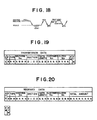
- Fig. 18 shows the sequence of total amount request in the transaction sequence. If the total amount request text is transmitted corresponding to the POLLING from the center machine 1 and therefore the transmitted data is accepted in the center machine 1, the text including total amount is transferred from the center machine 1. If the transmitted data is not accepted in the center machine 1, the state response "A" together with the error status is transferred.
- Fig. 19 shows the data format of the total amount request text, and section "0100" represents the command of total amount request.
- Fig. 20 shows the format of receiving data corresponding to this, and the total amount is added. If the thermal printer 6 is operated on the basis of the receiving data, the customer total receipt can be issued.
- the register mode changing switch 10 is set to the "REG" position, and the " * " key 20 is pushed so as to produce the total amount indicating mode, and then the clerk keys 15 are pushed, thereby the total amount may be indicated.
- Fig. 21 and Fig. 22 show the sequence of receipt issuing request (transaction request) in the transaction sequence.
- Fig. 21 shows the case of request acceptance, where text of the receipt issuing request is transmitted from side of the scale 2 in response to the POLLING from the center machine 1.
- Fig. 23 shows the data format of the text, and section "0101" represents the command of the receipt issuing request. If the transmitted data from side of the scale 2 is accepted in the center machine 1 (ACK response), the center machine 1 transfers the print data to the scale 2 on the basis of the transaction data or the like.
- Fig. 24 shows the format of the receiving data in the scale 2, and various data of item, total as hereinbefore described are included.
- Fig. 22 shows the sequence in the case of rejection of the receipt issuing request and the process is ended by transmitting the "A" status.
- the transaction data is controlled finely by the center machine, not only the receipt can be issued at the center machine but also it can be issued at any scale by receipt issuing request from side of the scale, so that the in-line system becomes suited to each shop and easy for the use.
- the customer total receipt can be issued on the basis of the clerk number control, thereby articles desired by the customer can be readily known and the fine customer service such as consulting sale or article advice can be performed. If the customer does not yet decide what is to be bought, the active selling service such as article explaining, cooking manner or menu can be made.
Landscapes
- Physics & Mathematics (AREA)
- General Physics & Mathematics (AREA)
- Engineering & Computer Science (AREA)
- Computer Networks & Wireless Communication (AREA)
- Cash Registers Or Receiving Machines (AREA)
Applications Claiming Priority (4)
| Application Number | Priority Date | Filing Date | Title |
|---|---|---|---|
| JP179093/84 | 1984-08-28 | ||
| JP59179094A JPH0612295B2 (ja) | 1984-08-28 | 1984-08-28 | 計量インラインシステム |
| JP179094/84 | 1984-08-28 | ||
| JP59179093A JPH0658254B2 (ja) | 1984-08-28 | 1984-08-28 | 計量インラインシステム |
Publications (3)
| Publication Number | Publication Date |
|---|---|
| EP0176242A2 true EP0176242A2 (fr) | 1986-04-02 |
| EP0176242A3 EP0176242A3 (en) | 1988-07-27 |
| EP0176242B1 EP0176242B1 (fr) | 1991-01-16 |
Family
ID=26499054
Family Applications (1)
| Application Number | Title | Priority Date | Filing Date |
|---|---|---|---|
| EP85306014A Expired EP0176242B1 (fr) | 1984-08-28 | 1985-08-23 | Système compteur connecté en série |
Country Status (3)
| Country | Link |
|---|---|
| US (1) | US4655304A (fr) |
| EP (1) | EP0176242B1 (fr) |
| DE (1) | DE3581347D1 (fr) |
Cited By (4)
| Publication number | Priority date | Publication date | Assignee | Title |
|---|---|---|---|---|
| EP0382016A3 (en) * | 1989-02-07 | 1990-09-26 | Tokyo Electric Co., Ltd. | Electronic input-display apparatus |
| WO1995025263A1 (fr) * | 1994-03-14 | 1995-09-21 | Siemens Nixdorf Informationssysteme Ag | Appareil de mesure avec affichage pouvant etre actionne par un dispositif supplementaire |
| DE19616986C1 (de) * | 1996-04-27 | 1997-07-03 | Csb Syst Software Entwicklung | Verfahren zur Erfassung von fehlerbehafteten Warenaus- und -eingängen |
| DE10039705A1 (de) * | 2000-08-14 | 2002-02-28 | Mettler Toledo Albstadt Gmbh | Gerät zum Abwickeln einzelner Vorgänge |
Families Citing this family (6)
| Publication number | Priority date | Publication date | Assignee | Title |
|---|---|---|---|---|
| NZ215998A (en) * | 1985-05-02 | 1989-10-27 | Ishida Scale Mfg Co Ltd | Electronic scales store merchandise data transmitted from central data base |
| JPH0740260B2 (ja) * | 1985-12-24 | 1995-05-01 | 株式会社テック | 電子料金秤の集計メモリ処理装置 |
| US4969112A (en) * | 1988-10-14 | 1990-11-06 | Moore Industries-International, Inc. | Wireless weighing system |
| DE4404892A1 (de) * | 1994-02-16 | 1995-08-17 | Multipond Waegetechnik Gmbh | Teilmengenkombinationswaage mit Bus-Leitung |
| US6639156B2 (en) * | 1999-12-30 | 2003-10-28 | Tom J. Luke | Method and device for monitoring inventory |
| US20050086133A1 (en) * | 2003-01-08 | 2005-04-21 | Scherer William H. | System and method for sensing and analyzing inventory levels and consumer buying habits |
Family Cites Families (11)
| Publication number | Priority date | Publication date | Assignee | Title |
|---|---|---|---|---|
| US3459271A (en) * | 1967-10-12 | 1969-08-05 | Reliance Electric & Eng Co | Computing weighing scale system |
| US3632988A (en) * | 1969-01-22 | 1972-01-04 | Tokico Ltd | Concentric sales control system and apparatus in fuel supplying and servicing station |
| US3716697A (en) * | 1971-05-05 | 1973-02-13 | Fmc Corp | Automatic marketing system |
| US3899775A (en) * | 1973-04-13 | 1975-08-12 | Msi Data Corp | Automatic store transaction system and terminal therefor |
| US3906208A (en) * | 1974-04-29 | 1975-09-16 | Hobart Corp | Computing scale system |
| AU4403679A (en) * | 1978-02-10 | 1979-08-16 | Data Scales Ltd. | Price computing weighing machine system |
| JPS5820071B2 (ja) * | 1979-06-15 | 1983-04-21 | オムロン株式会社 | 電子式キヤツシユレジスタの群管理方式 |
| US4398250A (en) * | 1979-10-31 | 1983-08-09 | Casio Computer Co., Ltd. | Electronic cash register mutual transmission system for plurality of cash registers |
| DE3003255C2 (de) * | 1980-01-30 | 1987-03-19 | Espera-Werke Gmbh, 4100 Duisburg | Wäge-, Preisrechen- und Registrieranlage für Thekenbedienung in Handelsgeschäften |
| DE3044394A1 (de) * | 1980-11-25 | 1982-07-15 | Bizerba-Werke Wilhelm Kraut GmbH & Co KG, 7460 Balingen | Waege- und kassiervorrichtung |
| US4574352A (en) * | 1983-03-07 | 1986-03-04 | Pitney Bowes Inc. | Drop shipment mailing system |
-
1985
- 1985-08-22 US US06/768,054 patent/US4655304A/en not_active Expired - Lifetime
- 1985-08-23 DE DE8585306014T patent/DE3581347D1/de not_active Expired - Lifetime
- 1985-08-23 EP EP85306014A patent/EP0176242B1/fr not_active Expired
Cited By (6)
| Publication number | Priority date | Publication date | Assignee | Title |
|---|---|---|---|---|
| EP0382016A3 (en) * | 1989-02-07 | 1990-09-26 | Tokyo Electric Co., Ltd. | Electronic input-display apparatus |
| US5153585A (en) * | 1989-02-07 | 1992-10-06 | Tokyo Electric Co., Ltd. | Electronic input-display apparatus |
| WO1995025263A1 (fr) * | 1994-03-14 | 1995-09-21 | Siemens Nixdorf Informationssysteme Ag | Appareil de mesure avec affichage pouvant etre actionne par un dispositif supplementaire |
| DE19616986C1 (de) * | 1996-04-27 | 1997-07-03 | Csb Syst Software Entwicklung | Verfahren zur Erfassung von fehlerbehafteten Warenaus- und -eingängen |
| DE10039705A1 (de) * | 2000-08-14 | 2002-02-28 | Mettler Toledo Albstadt Gmbh | Gerät zum Abwickeln einzelner Vorgänge |
| US6900396B2 (en) | 2000-08-14 | 2005-05-31 | Mettler-Toledo (Albstadt) Gmbh | Device for handling individual processes |
Also Published As
| Publication number | Publication date |
|---|---|
| DE3581347D1 (de) | 1991-02-21 |
| EP0176242A3 (en) | 1988-07-27 |
| US4655304A (en) | 1987-04-07 |
| EP0176242B1 (fr) | 1991-01-16 |
Similar Documents
| Publication | Publication Date | Title |
|---|---|---|
| US4655304A (en) | Counting in-line system | |
| US4396985A (en) | Electronic cash register system for food dispensing business | |
| US4360872A (en) | Electronic cash register system | |
| US4901237A (en) | Electronic scale system | |
| US4893237A (en) | Interconnected sales data registration and payment settlement system | |
| US4493037A (en) | Retail terminal | |
| US4847762A (en) | ECR having means for establishing a data format and processing entered data in accordance with an established data format | |
| JPS6340995A (ja) | Pos端末装置 | |
| CA1223359A (fr) | Dispositif d'alignement automatique pour caisse electronique | |
| KR910003983B1 (ko) | 계량 인라인 시스템 | |
| JPS6141419B2 (fr) | ||
| JPH0612295B2 (ja) | 計量インラインシステム | |
| JPS63140367A (ja) | Pos端末装置 | |
| JPS584472A (ja) | 電子式キヤツシユレジスタ | |
| JP2505249B2 (ja) | 商品販売デ―タ処理装置 | |
| JP3112632B2 (ja) | 商品販売登録データ処理装置 | |
| JPH033023A (ja) | キー入力装置 | |
| JPH0766472B2 (ja) | 売上データ処理装置 | |
| JPH079661B2 (ja) | 取引処理装置 | |
| Specifications | System Overview | |
| JP2023001701A (ja) | オーダシステム、情報処理装置及びその制御プログラム、オーダ入力方法 | |
| JPH0360677B2 (fr) | ||
| JPS6053820A (ja) | レシ−トプリンタ付電子料金秤 | |
| JPS63128946A (ja) | ラベルプリンタ | |
| JPH071516B2 (ja) | 電子式キヤツシユレジスタ |
Legal Events
| Date | Code | Title | Description |
|---|---|---|---|
| PUAI | Public reference made under article 153(3) epc to a published international application that has entered the european phase |
Free format text: ORIGINAL CODE: 0009012 |
|
| AK | Designated contracting states |
Kind code of ref document: A2 Designated state(s): BE DE FR GB NL |
|
| PUAL | Search report despatched |
Free format text: ORIGINAL CODE: 0009013 |
|
| AK | Designated contracting states |
Kind code of ref document: A3 Designated state(s): BE DE FR GB NL |
|
| 17P | Request for examination filed |
Effective date: 19881230 |
|
| 17Q | First examination report despatched |
Effective date: 19890419 |
|
| GRAA | (expected) grant |
Free format text: ORIGINAL CODE: 0009210 |
|
| AK | Designated contracting states |
Kind code of ref document: B1 Designated state(s): BE DE FR GB NL |
|
| REF | Corresponds to: |
Ref document number: 3581347 Country of ref document: DE Date of ref document: 19910221 |
|
| ET | Fr: translation filed | ||
| PLBE | No opposition filed within time limit |
Free format text: ORIGINAL CODE: 0009261 |
|
| STAA | Information on the status of an ep patent application or granted ep patent |
Free format text: STATUS: NO OPPOSITION FILED WITHIN TIME LIMIT |
|
| 26N | No opposition filed | ||
| PGFP | Annual fee paid to national office [announced via postgrant information from national office to epo] |
Ref country code: FR Payment date: 20010810 Year of fee payment: 17 |
|
| PGFP | Annual fee paid to national office [announced via postgrant information from national office to epo] |
Ref country code: DE Payment date: 20010813 Year of fee payment: 17 |
|
| PGFP | Annual fee paid to national office [announced via postgrant information from national office to epo] |
Ref country code: GB Payment date: 20010822 Year of fee payment: 17 |
|
| PGFP | Annual fee paid to national office [announced via postgrant information from national office to epo] |
Ref country code: NL Payment date: 20010830 Year of fee payment: 17 |
|
| PGFP | Annual fee paid to national office [announced via postgrant information from national office to epo] |
Ref country code: BE Payment date: 20011016 Year of fee payment: 17 |
|
| REG | Reference to a national code |
Ref country code: GB Ref legal event code: IF02 |
|
| PG25 | Lapsed in a contracting state [announced via postgrant information from national office to epo] |
Ref country code: GB Free format text: LAPSE BECAUSE OF NON-PAYMENT OF DUE FEES Effective date: 20020823 |
|
| PG25 | Lapsed in a contracting state [announced via postgrant information from national office to epo] |
Ref country code: BE Free format text: LAPSE BECAUSE OF NON-PAYMENT OF DUE FEES Effective date: 20020831 |
|
| BERE | Be: lapsed |
Owner name: *TOKYO ELECTRIC CO. LTD Effective date: 20020831 |
|
| PG25 | Lapsed in a contracting state [announced via postgrant information from national office to epo] |
Ref country code: NL Free format text: LAPSE BECAUSE OF NON-PAYMENT OF DUE FEES Effective date: 20030301 Ref country code: DE Free format text: LAPSE BECAUSE OF NON-PAYMENT OF DUE FEES Effective date: 20030301 |
|
| GBPC | Gb: european patent ceased through non-payment of renewal fee |
Effective date: 20020823 |
|
| PG25 | Lapsed in a contracting state [announced via postgrant information from national office to epo] |
Ref country code: FR Free format text: LAPSE BECAUSE OF NON-PAYMENT OF DUE FEES Effective date: 20030430 |
|
| NLV4 | Nl: lapsed or anulled due to non-payment of the annual fee |
Effective date: 20030301 |
|
| REG | Reference to a national code |
Ref country code: FR Ref legal event code: ST |