EP0176263A2 - Optische Faser - Google Patents
Optische Faser Download PDFInfo
- Publication number
- EP0176263A2 EP0176263A2 EP85306162A EP85306162A EP0176263A2 EP 0176263 A2 EP0176263 A2 EP 0176263A2 EP 85306162 A EP85306162 A EP 85306162A EP 85306162 A EP85306162 A EP 85306162A EP 0176263 A2 EP0176263 A2 EP 0176263A2
- Authority
- EP
- European Patent Office
- Prior art keywords
- preform
- silica
- rod
- preforms
- further characterized
- Prior art date
- Legal status (The legal status is an assumption and is not a legal conclusion. Google has not performed a legal analysis and makes no representation as to the accuracy of the status listed.)
- Granted
Links
Images
Classifications
-
- C—CHEMISTRY; METALLURGY
- C03—GLASS; MINERAL OR SLAG WOOL
- C03B—MANUFACTURE, SHAPING, OR SUPPLEMENTARY PROCESSES
- C03B37/00—Manufacture or treatment of flakes, fibres, or filaments from softened glass, minerals, or slags
- C03B37/01—Manufacture of glass fibres or filaments
- C03B37/012—Manufacture of preforms for drawing fibres or filaments
- C03B37/014—Manufacture of preforms for drawing fibres or filaments made entirely or partially by chemical means, e.g. vapour phase deposition of bulk porous glass either by outside vapour deposition [OVD], or by outside vapour phase oxidation [OVPO] or by vapour axial deposition [VAD]
- C03B37/01446—Thermal after-treatment of preforms, e.g. dehydrating, consolidating, sintering
-
- C—CHEMISTRY; METALLURGY
- C03—GLASS; MINERAL OR SLAG WOOL
- C03B—MANUFACTURE, SHAPING, OR SUPPLEMENTARY PROCESSES
- C03B37/00—Manufacture or treatment of flakes, fibres, or filaments from softened glass, minerals, or slags
- C03B37/01—Manufacture of glass fibres or filaments
- C03B37/012—Manufacture of preforms for drawing fibres or filaments
- C03B37/01205—Manufacture of preforms for drawing fibres or filaments starting from tubes, rods, fibres or filaments
- C03B37/01211—Manufacture of preforms for drawing fibres or filaments starting from tubes, rods, fibres or filaments by inserting one or more rods or tubes into a tube
-
- C—CHEMISTRY; METALLURGY
- C03—GLASS; MINERAL OR SLAG WOOL
- C03B—MANUFACTURE, SHAPING, OR SUPPLEMENTARY PROCESSES
- C03B37/00—Manufacture or treatment of flakes, fibres, or filaments from softened glass, minerals, or slags
- C03B37/01—Manufacture of glass fibres or filaments
- C03B37/012—Manufacture of preforms for drawing fibres or filaments
- C03B37/014—Manufacture of preforms for drawing fibres or filaments made entirely or partially by chemical means, e.g. vapour phase deposition of bulk porous glass either by outside vapour deposition [OVD], or by outside vapour phase oxidation [OVPO] or by vapour axial deposition [VAD]
- C03B37/01466—Means for changing or stabilising the diameter or form of tubes or rods
- C03B37/01473—Collapsing
-
- C—CHEMISTRY; METALLURGY
- C03—GLASS; MINERAL OR SLAG WOOL
- C03C—CHEMICAL COMPOSITION OF GLASSES, GLAZES OR VITREOUS ENAMELS; SURFACE TREATMENT OF GLASS; SURFACE TREATMENT OF FIBRES OR FILAMENTS MADE FROM GLASS, MINERALS OR SLAGS; JOINING GLASS TO GLASS OR OTHER MATERIALS
- C03C13/00—Fibre or filament compositions
- C03C13/04—Fibre optics, e.g. core and clad fibre compositions
- C03C13/045—Silica-containing oxide glass compositions
-
- C—CHEMISTRY; METALLURGY
- C03—GLASS; MINERAL OR SLAG WOOL
- C03B—MANUFACTURE, SHAPING, OR SUPPLEMENTARY PROCESSES
- C03B2201/00—Type of glass produced
- C03B2201/06—Doped silica-based glasses
- C03B2201/08—Doped silica-based glasses doped with boron or fluorine or other refractive index decreasing dopant
- C03B2201/12—Doped silica-based glasses doped with boron or fluorine or other refractive index decreasing dopant doped with fluorine
-
- Y—GENERAL TAGGING OF NEW TECHNOLOGICAL DEVELOPMENTS; GENERAL TAGGING OF CROSS-SECTIONAL TECHNOLOGIES SPANNING OVER SEVERAL SECTIONS OF THE IPC; TECHNICAL SUBJECTS COVERED BY FORMER USPC CROSS-REFERENCE ART COLLECTIONS [XRACs] AND DIGESTS
- Y10—TECHNICAL SUBJECTS COVERED BY FORMER USPC
- Y10S—TECHNICAL SUBJECTS COVERED BY FORMER USPC CROSS-REFERENCE ART COLLECTIONS [XRACs] AND DIGESTS
- Y10S65/00—Glass manufacturing
- Y10S65/15—Nonoxygen containing chalogenides
- Y10S65/16—Optical filament or fiber treatment with fluorine or incorporating fluorine in final product
Definitions
- the invention relates to a method for manufacturing optical waveguide. It has particular application to the manufacture of optical waveguide having a fluorine doned silica cladding and a pure or doped silica core.
- Optical waveguide having a fluorine doped silica cladding is described in United States patent 4,082,420 (Shiraishi et al).
- the optical waveguide is made by a flame hydrolysis method in which silicon tetrachloride and silicon tetrafluoride are fed to an oxygen-hydrogen burner to form a soot which is deposited onto the surface of a pure silica rod. The rod is then heated to consolidate the soot into a composite glass preform and fiber is drawn from the preform.
- a method according to the present invention for fabricating a fluorine doped silica clad fiber takes advantage of certain merits of the flame hydrolysis process.
- flame hydrolysis is characterized by a high rate of deposition so large silica preforms can be rapidly grown.
- the advantages of large preforms is that they can be used to make very long fibers without the need for splices or connections. Also during fiber drawing, the preforms do not have to be replaced so often in the fiber drawing towers so reducing labour costs.
- United States Patent 3,459,522 (Elmer) the water 0176263 content in a porous silica body can be reduced to exceedingly low levels by drying in a chlorine containing atmosphere.
- optical waveguide comprising:
- the two preforms are dried individually after preparation thereof and are again dried together after the rod preform is inserted into the tube preform.
- the preforms can be dried in a chlorine containing atmosphere.
- the particulate silica is preferably produced by a flame hydrolysis action in which silicon tetrachloride dissociates in an oxygen-hydrogen burner flame.
- the rod preform can be deposited on the end of a silica seed rod, the seed rod being progressively axially moved away from the burner flame as the silica is deposited so as to maintain a substantially constant spacing between the burner flame and the end of the rod preform.
- the tubular preform is preferably deposited on the outside curved surface of a tapered cylindrical carbon mandrel, the mandrel being rotated around its axis as the burner is reciprocated along the length of the mandrel.
- the chlorine is preferably mixed with helium, the drying chamber being maintained at a temperature of the order of 1000°C for several hours.
- the fluorine gas for example, sulphur hexafluoride or silicon tetrafluoride, is mixed with helium and a temperature of 1000°C is maintained for several hours.
- the drying and fluorine diffusion gases are preferably piped respectively through the drying and diffusion chambers at a rate of about 1 litres per minute.
- the final chlorine drying step can be performed in a furnace which has within it a zone sintering region for substantially raising the temperature of the composite preform above 1000°C whereby the composite preform need not be removed from the furnace after the final drying step and before consolidating the particulate silica into fused silica.
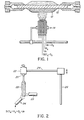
- a carbon mandrel 10 extending horizontally between two quartz chucks 12. Adjacent the mandrel and mounted for reciprocation along a track parallel to the mandrel is a burner 14 to which silicon tetrachloride, hydrogen and oxygen are fed. Silicon tetrachloride entrained within a stream of oxygen is fed to a central chamber within the burner. Argon which separates the silicon tetrachloride vapor from the burner gases within the burner is fed to a second chamber. Hydrogen is fed to a third chamber and a mixture of argon and oxygen is fed to the outer burner chamber.
- the flow rates are 1.5 litres per minute of oxygen to the first chamber, 1.2 litres per minute of argon to the second chamber, 5 litres per minute of hydrogen to the third chamber and 3 litres per minute of argon with 1.5 litres per minute of oxygen to the outer chamber.
- the mandrel 10 is rotated at 30 rpm and the burner is reciprocated along the length of the mandrel at 8 centimeters per minute.
- the rate of growth of silica on the outside of the mandrel depends on the size of the mandrel and previously formed particulate silica.
- the initial growth rate is of the order of 0.5 grams per minute, but as the deposition of silica results in a preform 12 having an outer diameter of the order of 8 centimeters, a silica deposition rate of greater than 2 grams per minute can be achieved.
- a silica deposition rate of greater than 2 grams per minute can be achieved.
- the mandrel and the silica contract to different extents during cooling to allow easy removal of the silica from the mandrel.
- the mandrel can have a slight taper to further aid in preform removal.
- the preparation of a cylindrical rod preform 28 is in many respects similar to preparation of the tubular preform.
- the rod preform 28 is deposited axially.
- a silica rod 18 is mounted within a chuck 20 which is rotated at 30 rpm using a motor 22.
- a burner 24 which is similar in all respects to the burner used in the preparation of the tubular preform is fixed to direct silica upwardly onto the end of the silica seed rod 18.
- the burner flame is directed angularly at the end of the seed rod and an air flow around the end of the rod is generated using a pipe 25 connected to a pump (not shown).
- the seed rod 18 is progressively raised by moving a supporting jig 24 relative to the support column 26.
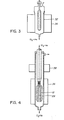
- the preform is mounted vertically within a quartz chamber 32 which is itself located within a furnace 34.
- a mixture of chlorine and helium is then piped through the chamber at a temperature of 1000°C for 4 hours and at a chlorine and helium flow rate each of 1 litres per minute.
- Hydrogen within the preform combines with the chlorine to produce hydrogen chloride. Excess chlorine and hydrogen chloride are exhausted from the chamber leaving chlorine within the particulate silica. The chlorine is too large an atom to stay within the glass matrix in a subsequent sintering step so is driven off as chlorine gas.
- the tubular preform while it is within the drying chamber it is subsequently subjected to a fluorine atmosphere.
- a fluorine producing gas such as sulphur hexafluoride or silicon tetrafluoride together with helium is piped through the chamber at a flow rate of 1 litres per minute for each gas. Again the temperature is raised to 1000°C for a diffusion time of the order of 4 hours.
- the effect of heating within the fluorine atmosphere is to introduce fluorine into the silica matrix.
- the fluorine atom is substantially smaller than the chlorine atom so in a subsequent sintering step it is not driven out of the silica.
- the silica can be dried in fluorine and in effect the initial drying and fluorine doping steps are preformed together.
- the fluorination step produces HF in the presence of water and the HF quickly attacks the quartz furnace elements. Consequently, an HF resistant liner such as amorphous Si or platinum is needed in the furnace.
- the rod and tube preforms 12 and 28 are subsequently taken to a further drying furnace 36 which is combined with a zone sintering furnace 38.
- the rod preform is mounted concentrically within the tubular preform and within this combined furnace the two preforms are subjected to a final drying step and then to a zone sintering step in which firstly the outer tubular preform collapses onto the inner rod preform and secondly, the particulate material is consolidated into a fused transparent silica.
- the drying step is again performed in a chlorine-helium atmosphere at 1000°C for 5 hours.
- the zone sintering furnace raises the temperature of the preforms locally to about 1700°C when the collapse and consolidation of the particulate material occurs.
- the opportunity for moisture and contaminants to penetrate the particulate material is reduced. Once the particulate material has been consolidated into a fused silica, then the opportunity for water and other contaminants to penetrate the composite preform obtained is further reduced.
- the composite preform is subsequently placed in a vertical orientation drawing tower having a furnace zone at which the preform temperature is raised to about 2000°C which is higher than the silica softening point.
- Fiber is pulled from the lower end of the preform by a drum onto which the fiber is wound after being cooled and coated with a protective acrylate or silicone layer.
- the fiber has a high refractive index pure silica core and a relatively low index cladding.
Landscapes
- Chemical & Material Sciences (AREA)
- Engineering & Computer Science (AREA)
- Organic Chemistry (AREA)
- Materials Engineering (AREA)
- Geochemistry & Mineralogy (AREA)
- Life Sciences & Earth Sciences (AREA)
- Chemical Kinetics & Catalysis (AREA)
- General Life Sciences & Earth Sciences (AREA)
- General Chemical & Material Sciences (AREA)
- Manufacturing & Machinery (AREA)
- Physics & Mathematics (AREA)
- Thermal Sciences (AREA)
- Optics & Photonics (AREA)
- Manufacture, Treatment Of Glass Fibers (AREA)
- Glass Compositions (AREA)
Applications Claiming Priority (2)
| Application Number | Priority Date | Filing Date | Title |
|---|---|---|---|
| CA000463378A CA1236695A (en) | 1984-09-17 | 1984-09-17 | Optical fiber |
| CA463378 | 1984-09-17 |
Publications (3)
| Publication Number | Publication Date |
|---|---|
| EP0176263A2 true EP0176263A2 (de) | 1986-04-02 |
| EP0176263A3 EP0176263A3 (en) | 1989-06-07 |
| EP0176263B1 EP0176263B1 (de) | 1991-01-09 |
Family
ID=4128732
Family Applications (1)
| Application Number | Title | Priority Date | Filing Date |
|---|---|---|---|
| EP85306162A Expired EP0176263B1 (de) | 1984-09-17 | 1985-08-30 | Optische Faser |
Country Status (5)
| Country | Link |
|---|---|
| US (1) | US4648891A (de) |
| EP (1) | EP0176263B1 (de) |
| JP (1) | JPS6172646A (de) |
| CA (1) | CA1236695A (de) |
| DE (1) | DE3581250D1 (de) |
Cited By (9)
| Publication number | Priority date | Publication date | Assignee | Title |
|---|---|---|---|---|
| FR2583408A1 (fr) * | 1985-06-13 | 1986-12-19 | Heraeus Schott Quarzschmelze | Procede de production d'une preforme pour fibres optiques et utilisation d'un tube en verre de quartz pour produire une telle preforme. |
| EP0276311A4 (de) * | 1986-06-11 | 1988-10-06 | Sumitomo Electric Industries | Verfahren zur herstellung von basismaterial für optische fasern. |
| EP0159046A3 (en) * | 1984-04-20 | 1988-12-07 | Sumitomo Electric Industries Limited | Method for producing glass preform for single mode optical fiber |
| DE4133173A1 (de) * | 1991-10-07 | 1993-04-22 | Rheydt Kabelwerk Ag | Verfahren zum herstellen einer vorform fuer optische fasern |
| EP0718244A3 (de) * | 1994-12-20 | 1997-07-16 | Corning Inc | Verfahren zur Herstellung von optischen Fasern mit Brechungsindexabsenkung im Kernbereich der Faser |
| WO2000064825A1 (en) * | 1999-04-26 | 2000-11-02 | Corning Incorporated | Low water peak optical waveguide fiber and method of manufacturing same |
| WO2001032572A1 (de) * | 1999-11-02 | 2001-05-10 | Heraeus Quarzglas Gmbh & Co. Kg | Verfahren zur herstellung einer quarzglas-vorform für lichtleitfasern sowie nach dem verfahren hergestellte quarzglas-vorform |
| EP1188724A1 (de) * | 2000-08-01 | 2002-03-20 | Lucent Technologies Inc. | Verfahren zum Herstellen einer Vorform für optische Fasern mittels eines Stab-im-Rohr-Verfahrens |
| US6422042B1 (en) | 1994-12-20 | 2002-07-23 | Corning Incorporated | Rit method of making optical fiber having depressed index core region |
Families Citing this family (10)
| Publication number | Priority date | Publication date | Assignee | Title |
|---|---|---|---|---|
| US4775401A (en) * | 1987-06-18 | 1988-10-04 | American Telephone And Telegraph Company, At&T Bell Laboratories | Method of producing an optical fiber |
| US5039325A (en) * | 1990-01-02 | 1991-08-13 | At&T Bell Laboratories | Method for consolidating doped glass using an encapsulating structure |
| US4968339A (en) * | 1990-01-02 | 1990-11-06 | At&T Bell Laboratories | Method of fluorine doped modified chemical vapor deposition |
| US5076824A (en) * | 1990-05-14 | 1991-12-31 | At&T Bell Laboratories | Method of making fiber optical preform with pyrolytic coated mandrel |
| US6263706B1 (en) * | 1999-03-30 | 2001-07-24 | Deliso Evelyn M. | Method of controlling fluorine doping in soot preforms |
| US6574994B2 (en) | 2001-06-18 | 2003-06-10 | Corning Incorporated | Method of manufacturing multi-segmented optical fiber and preform |
| US6966201B2 (en) * | 2002-08-16 | 2005-11-22 | Furukawa Electric North America, Inc. | High-temperature sintering of soot bodies doped using molecular stuffing |
| US7021083B2 (en) * | 2003-01-29 | 2006-04-04 | Fitel Usa Corp. | Manufacture of high purity glass tubes |
| US9873629B2 (en) * | 2011-06-30 | 2018-01-23 | Corning Incorporated | Methods for producing optical fiber preforms with low index trenches |
| US10053386B2 (en) * | 2014-04-25 | 2018-08-21 | Corning Incorporated | Method for forming optical fiber and preforms |
Family Cites Families (9)
| Publication number | Priority date | Publication date | Assignee | Title |
|---|---|---|---|---|
| DE2536456C2 (de) * | 1975-08-16 | 1981-02-05 | Heraeus Quarzschmelze Gmbh, 6450 Hanau | Halbzeug für die Herstellung von Lichtleitfasern und Verfahren zur Herstellung des Halbzeugs |
| JPS54112218A (en) * | 1978-02-20 | 1979-09-03 | Nippon Telegr & Teleph Corp <Ntt> | Production of optical fiber |
| US4165223A (en) * | 1978-03-06 | 1979-08-21 | Corning Glass Works | Method of making dry optical waveguides |
| JPS6038345B2 (ja) * | 1978-11-07 | 1985-08-31 | 日本電信電話株式会社 | 光伝送用ガラス素材の製造方法 |
| JPS5852935B2 (ja) * | 1978-11-20 | 1983-11-26 | 三菱マテリアル株式会社 | 光伝送用素材の製造方法 |
| JPS603019B2 (ja) * | 1979-12-06 | 1985-01-25 | 三菱電線工業株式会社 | 光ファイバ母材の製法 |
| US4289517A (en) * | 1980-07-03 | 1981-09-15 | Corning Glass Works | Method of forming an optical waveguide preform |
| JPS58208146A (ja) * | 1982-05-27 | 1983-12-03 | Fujikura Ltd | 耐放射線用光フアイバ母材の製造方法 |
| DE3230199A1 (de) * | 1982-08-13 | 1984-02-16 | Siemens AG, 1000 Berlin und 8000 München | Verfahren zur herstellung einer glasfaser mit einem radialen brechzahlprofil |
-
1984
- 1984-09-17 CA CA000463378A patent/CA1236695A/en not_active Expired
-
1985
- 1985-04-08 US US06/721,104 patent/US4648891A/en not_active Expired - Lifetime
- 1985-08-30 DE DE8585306162T patent/DE3581250D1/de not_active Expired - Fee Related
- 1985-08-30 EP EP85306162A patent/EP0176263B1/de not_active Expired
- 1985-09-17 JP JP60203567A patent/JPS6172646A/ja active Pending
Cited By (12)
| Publication number | Priority date | Publication date | Assignee | Title |
|---|---|---|---|---|
| EP0159046A3 (en) * | 1984-04-20 | 1988-12-07 | Sumitomo Electric Industries Limited | Method for producing glass preform for single mode optical fiber |
| FR2583408A1 (fr) * | 1985-06-13 | 1986-12-19 | Heraeus Schott Quarzschmelze | Procede de production d'une preforme pour fibres optiques et utilisation d'un tube en verre de quartz pour produire une telle preforme. |
| EP0276311A4 (de) * | 1986-06-11 | 1988-10-06 | Sumitomo Electric Industries | Verfahren zur herstellung von basismaterial für optische fasern. |
| AU583715B2 (en) * | 1986-06-11 | 1989-05-04 | Sumitomo Electric Industries, Ltd. | Method for manufacturing basic material for optical fiber |
| DE4133173A1 (de) * | 1991-10-07 | 1993-04-22 | Rheydt Kabelwerk Ag | Verfahren zum herstellen einer vorform fuer optische fasern |
| EP0718244A3 (de) * | 1994-12-20 | 1997-07-16 | Corning Inc | Verfahren zur Herstellung von optischen Fasern mit Brechungsindexabsenkung im Kernbereich der Faser |
| US6422042B1 (en) | 1994-12-20 | 2002-07-23 | Corning Incorporated | Rit method of making optical fiber having depressed index core region |
| WO2000064825A1 (en) * | 1999-04-26 | 2000-11-02 | Corning Incorporated | Low water peak optical waveguide fiber and method of manufacturing same |
| US6477305B1 (en) | 1999-04-26 | 2002-11-05 | Corning Incorporated | Low water peak optical waveguide and method of manufacturing same |
| WO2001032572A1 (de) * | 1999-11-02 | 2001-05-10 | Heraeus Quarzglas Gmbh & Co. Kg | Verfahren zur herstellung einer quarzglas-vorform für lichtleitfasern sowie nach dem verfahren hergestellte quarzglas-vorform |
| EP1188724A1 (de) * | 2000-08-01 | 2002-03-20 | Lucent Technologies Inc. | Verfahren zum Herstellen einer Vorform für optische Fasern mittels eines Stab-im-Rohr-Verfahrens |
| US6446468B1 (en) | 2000-08-01 | 2002-09-10 | Fitel Usa Corp. | Process for fabricating optical fiber involving overcladding during sintering |
Also Published As
| Publication number | Publication date |
|---|---|
| DE3581250D1 (de) | 1991-02-14 |
| JPS6172646A (ja) | 1986-04-14 |
| US4648891A (en) | 1987-03-10 |
| EP0176263B1 (de) | 1991-01-09 |
| CA1236695A (en) | 1988-05-17 |
| EP0176263A3 (en) | 1989-06-07 |
Similar Documents
| Publication | Publication Date | Title |
|---|---|---|
| US4648891A (en) | Optical fiber | |
| US5203898A (en) | Method of making fluorine/boron doped silica tubes | |
| CA1251044A (en) | Fluorine doped optical waveguide | |
| US4772302A (en) | Optical waveguide manufacture | |
| US4082420A (en) | An optical transmission fiber containing fluorine | |
| CA1260684A (en) | Optical waveguide manufacture | |
| CN1221709A (zh) | 在1385nm处具有低损耗的光纤及其制造方法 | |
| US20120297837A1 (en) | Method for producing glass preform | |
| US4161505A (en) | Process for producing optical transmission fiber | |
| CN116375331B (zh) | 一种锥形光纤的制备方法与锥形光纤 | |
| US4734117A (en) | Optical waveguide manufacture | |
| CN116119919B (zh) | 一种锥形光纤的制备方法与锥形光纤 | |
| US4242375A (en) | Process for producing optical transmission fiber | |
| US4165152A (en) | Process for producing optical transmission fiber | |
| EP0177040B1 (de) | Verfahren zur Herstellung einer Glasvorform für optische Fasern | |
| EP0201937B1 (de) | Verfahren zur Herstellung einer Glasvorform für optische Fasern | |
| US4318726A (en) | Process for producing optical fiber preform | |
| CA1261127A (en) | Optical waveguide manufacture | |
| US20040118164A1 (en) | Method for heat treating a glass article | |
| JPH06263468A (ja) | ガラス母材の製造方法 | |
| KR100591085B1 (ko) | 싱글모드 광섬유용 모재의 제조 방법 | |
| JP4565221B2 (ja) | 光ファイバ用母材 | |
| JPH028973B2 (de) | ||
| JPH0327491B2 (de) | ||
| JPS63147840A (ja) | 石英ガラス材の製造方法 |
Legal Events
| Date | Code | Title | Description |
|---|---|---|---|
| PUAI | Public reference made under article 153(3) epc to a published international application that has entered the european phase |
Free format text: ORIGINAL CODE: 0009012 |
|
| AK | Designated contracting states |
Kind code of ref document: A2 Designated state(s): DE FR GB NL |
|
| PUAL | Search report despatched |
Free format text: ORIGINAL CODE: 0009013 |
|
| AK | Designated contracting states |
Kind code of ref document: A3 Designated state(s): DE FR GB NL |
|
| 17P | Request for examination filed |
Effective date: 19890623 |
|
| 17Q | First examination report despatched |
Effective date: 19900119 |
|
| GRAA | (expected) grant |
Free format text: ORIGINAL CODE: 0009210 |
|
| AK | Designated contracting states |
Kind code of ref document: B1 Designated state(s): DE FR GB NL |
|
| PG25 | Lapsed in a contracting state [announced via postgrant information from national office to epo] |
Ref country code: FR Effective date: 19910109 |
|
| REF | Corresponds to: |
Ref document number: 3581250 Country of ref document: DE Date of ref document: 19910214 |
|
| PG25 | Lapsed in a contracting state [announced via postgrant information from national office to epo] |
Ref country code: NL Effective date: 19910424 |
|
| EN | Fr: translation not filed | ||
| PG25 | Lapsed in a contracting state [announced via postgrant information from national office to epo] |
Ref country code: GB Effective date: 19910830 |
|
| PLBE | No opposition filed within time limit |
Free format text: ORIGINAL CODE: 0009261 |
|
| STAA | Information on the status of an ep patent application or granted ep patent |
Free format text: STATUS: NO OPPOSITION FILED WITHIN TIME LIMIT |
|
| 26N | No opposition filed | ||
| GBPC | Gb: european patent ceased through non-payment of renewal fee | ||
| PG25 | Lapsed in a contracting state [announced via postgrant information from national office to epo] |
Ref country code: DE Effective date: 19920501 |