EP0176323A2 - Auf minimalste Zeit basierte Steuerung einer elektronisch gesteuerten Kraftstoffeinspritzung für dieselmotoren - Google Patents
Auf minimalste Zeit basierte Steuerung einer elektronisch gesteuerten Kraftstoffeinspritzung für dieselmotoren Download PDFInfo
- Publication number
- EP0176323A2 EP0176323A2 EP85306683A EP85306683A EP0176323A2 EP 0176323 A2 EP0176323 A2 EP 0176323A2 EP 85306683 A EP85306683 A EP 85306683A EP 85306683 A EP85306683 A EP 85306683A EP 0176323 A2 EP0176323 A2 EP 0176323A2
- Authority
- EP
- European Patent Office
- Prior art keywords
- fuel
- actuator
- adjustment member
- signal
- control means
- Prior art date
- Legal status (The legal status is an assumption and is not a legal conclusion. Google has not performed a legal analysis and makes no representation as to the accuracy of the status listed.)
- Granted
Links
Images



Classifications
-
- F—MECHANICAL ENGINEERING; LIGHTING; HEATING; WEAPONS; BLASTING
- F02—COMBUSTION ENGINES; HOT-GAS OR COMBUSTION-PRODUCT ENGINE PLANTS
- F02D—CONTROLLING COMBUSTION ENGINES
- F02D41/00—Electrical control of supply of combustible mixture or its constituents
- F02D41/30—Controlling fuel injection
- F02D41/38—Controlling fuel injection of the high pressure type
- F02D41/40—Controlling fuel injection of the high pressure type with means for controlling injection timing or duration
- F02D41/406—Electrically controlling a diesel injection pump
- F02D41/407—Electrically controlling a diesel injection pump of the in-line type
-
- F—MECHANICAL ENGINEERING; LIGHTING; HEATING; WEAPONS; BLASTING
- F02—COMBUSTION ENGINES; HOT-GAS OR COMBUSTION-PRODUCT ENGINE PLANTS
- F02D—CONTROLLING COMBUSTION ENGINES
- F02D35/00—Controlling engines, dependent on conditions exterior or interior to engines, not otherwise provided for
- F02D35/0007—Controlling engines, dependent on conditions exterior or interior to engines, not otherwise provided for using electrical feedback
-
- F—MECHANICAL ENGINEERING; LIGHTING; HEATING; WEAPONS; BLASTING
- F02—COMBUSTION ENGINES; HOT-GAS OR COMBUSTION-PRODUCT ENGINE PLANTS
- F02D—CONTROLLING COMBUSTION ENGINES
- F02D41/00—Electrical control of supply of combustible mixture or its constituents
- F02D41/02—Circuit arrangements for generating control signals
- F02D41/14—Introducing closed-loop corrections
- F02D41/1401—Introducing closed-loop corrections characterised by the control or regulation method
-
- F—MECHANICAL ENGINEERING; LIGHTING; HEATING; WEAPONS; BLASTING
- F02—COMBUSTION ENGINES; HOT-GAS OR COMBUSTION-PRODUCT ENGINE PLANTS
- F02B—INTERNAL-COMBUSTION PISTON ENGINES; COMBUSTION ENGINES IN GENERAL
- F02B3/00—Engines characterised by air compression and subsequent fuel addition
- F02B3/06—Engines characterised by air compression and subsequent fuel addition with compression ignition
-
- F—MECHANICAL ENGINEERING; LIGHTING; HEATING; WEAPONS; BLASTING
- F02—COMBUSTION ENGINES; HOT-GAS OR COMBUSTION-PRODUCT ENGINE PLANTS
- F02D—CONTROLLING COMBUSTION ENGINES
- F02D41/00—Electrical control of supply of combustible mixture or its constituents
- F02D41/02—Circuit arrangements for generating control signals
- F02D41/14—Introducing closed-loop corrections
- F02D41/1401—Introducing closed-loop corrections characterised by the control or regulation method
- F02D2041/1413—Controller structures or design
- F02D2041/1415—Controller structures or design using a state feedback or a state space representation
-
- F—MECHANICAL ENGINEERING; LIGHTING; HEATING; WEAPONS; BLASTING
- F02—COMBUSTION ENGINES; HOT-GAS OR COMBUSTION-PRODUCT ENGINE PLANTS
- F02D—CONTROLLING COMBUSTION ENGINES
- F02D41/00—Electrical control of supply of combustible mixture or its constituents
- F02D41/02—Circuit arrangements for generating control signals
- F02D41/14—Introducing closed-loop corrections
- F02D41/1401—Introducing closed-loop corrections characterised by the control or regulation method
- F02D2041/1413—Controller structures or design
- F02D2041/143—Controller structures or design the control loop including a non-linear model or compensator
-
- F—MECHANICAL ENGINEERING; LIGHTING; HEATING; WEAPONS; BLASTING
- F02—COMBUSTION ENGINES; HOT-GAS OR COMBUSTION-PRODUCT ENGINE PLANTS
- F02D—CONTROLLING COMBUSTION ENGINES
- F02D41/00—Electrical control of supply of combustible mixture or its constituents
- F02D41/02—Circuit arrangements for generating control signals
- F02D41/14—Introducing closed-loop corrections
- F02D41/1401—Introducing closed-loop corrections characterised by the control or regulation method
- F02D2041/1433—Introducing closed-loop corrections characterised by the control or regulation method using a model or simulation of the system
-
- F—MECHANICAL ENGINEERING; LIGHTING; HEATING; WEAPONS; BLASTING
- F02—COMBUSTION ENGINES; HOT-GAS OR COMBUSTION-PRODUCT ENGINE PLANTS
- F02D—CONTROLLING COMBUSTION ENGINES
- F02D41/00—Electrical control of supply of combustible mixture or its constituents
- F02D41/20—Output circuits, e.g. for controlling currents in command coils
- F02D2041/202—Output circuits, e.g. for controlling currents in command coils characterised by the control of the circuit
- F02D2041/2034—Control of the current gradient
-
- Y—GENERAL TAGGING OF NEW TECHNOLOGICAL DEVELOPMENTS; GENERAL TAGGING OF CROSS-SECTIONAL TECHNOLOGIES SPANNING OVER SEVERAL SECTIONS OF THE IPC; TECHNICAL SUBJECTS COVERED BY FORMER USPC CROSS-REFERENCE ART COLLECTIONS [XRACs] AND DIGESTS
- Y02—TECHNOLOGIES OR APPLICATIONS FOR MITIGATION OR ADAPTATION AGAINST CLIMATE CHANGE
- Y02T—CLIMATE CHANGE MITIGATION TECHNOLOGIES RELATED TO TRANSPORTATION
- Y02T10/00—Road transport of goods or passengers
- Y02T10/10—Internal combustion engine [ICE] based vehicles
- Y02T10/40—Engine management systems
Definitions
- the present invention relates to an electronically controlled fuel injection system for controlling a fuel quantity to be injected into each cylinder of a diesel engine by a fuel injection pump, and in particular to such a system for controlling an actuator of the fuel injection pump by means of a servo mechanism so that a fuel quantity adjusting member operatively responsive to the energization of the actuator is controlled for a high precision positioning thereof.
- a PID (Proportional Integral Differential) control process is employed in a positioning servo system for the purpose of controlling so that an actual position of the fuel injection adjustment member coincides with a desired position thereof corresponding to optimum injection fuel quantity derived as a function of engine operating conditions determined on the basis of engine operating parameters.
- a PID control servo system is disclosed in Japanese Laid-Open Patent Application No. 59-25047.
- an electronically controlled fuel injection system which avoids all of the above-noted problems by employing, as a replacement of the PID control system based on the classic control theory, the minimum time control system on the basis of the nonlinear optimum control theory of the modern control theory for the positioning servo mechnisim.
- the technique of the present invention involves employing a minimum time control system for determining a control amount value of an actuator so that an actual position of a fuel adjusting member coincides with a desired position, the control amount -value being obtained in accordance with an nonlinear dynamic model of the actuator.
- a further feature of this invention involves performing the minimum time control operation in view of the variations of lubricating oil temperature of the fuel injection pump.
- the present invention not only makes possible a further quick position adjustment of the fuel adjustment member, but also offers the very significant advantage to enabling servo operations with high accuracy, high reliability and high speed, that it is difficult to obtain in accordance with the PID control or linear control theory.
- a system for controlling a fuel quantity to be injected into each cylinder of a diesel engine by a fuel injection pump comprising: an actuator attached to said fuel injection pump; a fuel adjustment member operatively coupled to said fuel injection pump and responsive to an energization.
- said actuator for adjusting a quantity of fuel to be injected into said each cylinder of said diesel engine; sensor means for sensing an actual position of said fuel adjustment member and generating a signal indicative of said actual position; sensor means for sensing engine operating parameters; means for detecting an operating condition of said engine in accordance with the sensed engine operating parameters;-fuel quantity control means for calculating a fuel quantity necessary for the detected engine operating condition and generate a signal indicative of a desired position of said fuel adjustment member corresponding to the calculated fuel quantity; servo control means responsive to said signal from said actual position sensor means and said signal from said fuel quantity control means for computing a control input value and producing an output signal so that the actual position of said fuel adjustment member sensed by said actual position sensor means is coincident with the desired position thereof indicated by said signal from said fuel quantity control means, said servo control means including minimum time control means deriving said control input value on the basis of a nonlinear dynamic model of said actuator.
- a system for controlling a fuel quantity to be injected into each cylinder of a diesel engine by a fuel injection pump comprising: an actuator attached to said fuel injection pump; a fuel adjustment member operatively coupled to said fuel injection pump and responsive to an energization of said actuator for adjusting a quantity of fuel to be injected into said each cylinder of said diesel engine; first sensor means for sensing an actual position of said fuel adjustment member and generating a signal indicative of the sensed actual position; second sensor means for sensing a lubricating oli temperature of said fuel injection pump and generating a signal indicative of the sensed temperature; third sensor means for sensing engine operating parameters; means for detecting an operating condition of said engine in accordance with the sensed engine operating parameters; fuel quantity control means for calculating a fuel quantity necessary for the detected engine operating condition and generate a signal indicative of a desired position of said fuel adjustment member corresponding to the calculated fuel quantity; servo control means responsive to said signal from said first sensor means, said signal from
- FIG. 1 there is schematically illustrated an electronically controlled fuel injection system including a positioning servo unit according to the present invention incorporated with an in-line fuel injection pump 5 of a diesel engine having an actuator 82, a fuel adjustment member 83, such as a control rack, operatively responsive to the energization of the actuator 82, and a detector 84 for detecting an actual position of the fuel adjustment member.
- a positioning servo unit according to the present invention incorporated with an in-line fuel injection pump 5 of a diesel engine having an actuator 82, a fuel adjustment member 83, such as a control rack, operatively responsive to the energization of the actuator 82, and a detector 84 for detecting an actual position of the fuel adjustment member.
- the electronically controlled fuel injection system comprises a detector 1 for detecting engine operating conditions, an injection fuel amount control unit 2 including a well known microcomputer having a microprocessor or central processing unit (CPU), and a positioning servo unit 3 also including a well known microcomputer.
- the engine operating conditions are determined in accordance with engine operating parameters including engine coolant temperature, intake airflow amount, engine speed, throttle valve opening degree and so on which are measured by various engine condition sensors attached to the engine.
- the injection fuel amount control unit 2- derives a desired injection fuel amount from a map provided on a memory of the microcomputer as a function of the engine operating conditions detected by the detector 1 and produces a desired fuel adjustment member position signal indicative of the desired injection fuel amount.
- the positioning servo unit 3 in response to the desired position signal Pr produced by the control unit 2 and an output signal P of the detector 84 indicative of the present actual member position, controls the actuator 82 so that the actual position of the fuel adjustment member 83 coincides with the desired position thereof.
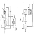
- Fig. 2 is a schematic block diagram showing the detail arrangement of the positioning servo system of Fig. 1.
- the positioning servo system comprises a minimum time control unit 7, a controlled system 8, and a speed estimation unit 9.
- the minimum time control unit 7 is arranged to produce a control input signal U of the controlled system 8 in accordance with a signal indicative of a deviation P E between a desired position Pr of the fuel adjustment member 83 and an actual position P thereof, a current I passing through the actuator 82, and an estimated speed value V of the fuel adjustment member 83 generated by the speed estimation unit 9.
- the control input signal U is a binary signal, for example, ON-OFF control signal for an actuator-drive transistor.
- the controlled system 8 is responsive to the control input signal U and generate a signal indicating the actual position of the fuel adjustment member 83 and a signal indicating a current value I passing through the actuator 82, both being control output signals thereof.
- the arrangement of the controlled system 8 is illustrated in detail in Fig. 3, which includes an actuator drive circuit 81, the actuator 82, fuel adjustment member 83 and actual position detector 84.
- the actuator drive circuit 81 comprises a switching elememt such as power transistor, power FET or the like and controls a voltage to be applied to the actuator 82.
- the circuit 81 includes resistor or the like and thereby perform the detection of the current I passing through the actuator 82.
- a linear solenoid actuator is employed which changes the position of the fuel adjustment member 83 in response to the energization thereof.
- the actual position detector 84 is of variable inductance type which is well known in the art.
- the speed estimation unit 9 is provided for estimating the speed of the fuel adjustment member 83. It is possible that the estimation speed value V thereof is found not only by merely differentiating a signal P indicative of the actual position thereof, but also, if a noise is introduced on the actual position signal P, is calculated by means of a state observer arranged on the basis of the dynamic model of the controlled system 8.
- the equation (10) can be performed using a circuit shown in Fig. 4.
- the circuit comprises a g-calculating means 71 and a comparator 72.
- the g-calculating means 71 receives the deviation signal P E , i.e. (P - Pr) and a signal indicative of the estimation speed valuer and calculates the function g, the result is fed to the comparator 72 and thereby compared with the current I passing through the actuator. In accordance with the results of the comparison, the actuator drive element is on-off controlled. Furthermore, as shown in Fig.. 5, as a result of providing an integral compensation means 73 for adding the integral value of deviation P E to the current I, it is possible to prevent from the characteristic change of the function f caused by a secular change.
- the function g is derived from a map stored in a read only memory (ROM) as a function of P - Pr and V.
- Fig. 7 illustrates an example of the map. This map is established on the basis of a nonlinear dynamic model of the actuator 82.
- Fig. 6 is a flow chart describing the operation of the positioning servo system in the case that the integral compensation is not effected.
- a step 100 the CPU computes the deviation P E between a desired position Pr of the fuel adjustment member 83 and an actual position P thereof.
- a step 101 follows to calculate an estimation speed value V by differentiating the-actual position P or using a state observer generally employed for the purpose of the estimation of speed.
- a step 102 is then executed to calculate a function g (P E , V) using, for example, the map as shown in Fig. 7 and thereby to obtain a current value I 1 .
- the CPU advances to a step 103 in which the current value I 1 obtained in the step 102 is compared with a current value I passing through the actuator 82.
- a step 104 follows to set the control input U to the ON-condition, on the other hand, if not, a step 105 follows to set it to the OFF-condition.
- This routine is repeatedly executed-so that the fuel adjjustment member 83 is controlled to coincide with a desired position in a minimum time period.
- FIGs. 8 to 13 Illustrated in Figs. 8 to 13 is a further embodiment of the present invention similar to the embodiment shown in Figs. 1 to 7 with the exception that it involves performing the minimum time control operation in accordance with engine operating parameters including a lubricating oil temperature of the fuel injection pump. Accordingly, parts corresponding to those of the first embodiment shown in Figs. 1 to 7 are marked with the same reference numerals and characters, the description thereof are omitted for brevity.
- the variations of the lubricating oil viscosity result in making worse the servo characteristics and further reducing the stability and responsibility of the servo system. Therefore, in order to eliminate these problems associated with the variations thereof, it is desirable to use the lubricating oil temperature as one of servo control parameters.
- Fig. 8 is a schematic block diagram illustrating an electronically controlled fuel injection system according to the second embodiment of this invention. It is seen from Fig. 8 that a lubricating oil temperature detector 85 is further attached to the fuel -injection pump 5 so that a signal indicative of a lubricating oil temperature T is supplied to the positioning servo unit 3.
- the lubricating oil temperature detector 85 comprises an element, such as thermisor, capable of measuring temperatures of the lubricating oil in the pump 5.
- the deteail arrangement of the positioning servo unit 3 is illustrated in Fig. 9 which comprises the minimum time control unit 7, controlled system 8 and speed estimation unit 9.
- the controlled system 8 is responsive to a control input signal U from the minimum time control unit 7, and generate an actual position signal U, a actuator current signal I and further a lubricating oil temperature signal T which are used as parameters for the minimum time control operation.
- Fig. 10 illustrates the detail arrangement of the controlled system 8.
- U the actuator 82 is energized by the actuator drive circuit 81 and the energization of the actuator 82 causes the fuel adjustment member 83 to be controlled to approach to a desired position indicated by the control input signal U.
- the actual position detector 84 again detects the newly set position of the fuel adjustment member 83 and generate an actual position signal P.
- the lubricating oil temperature detector 85 detects a temperature of the oil lubricating the fuel adjustment member 83 and generates a signal T indicative of the detected oil temperature.
- Aa actuator current signal is supplied from the actuator drive circuit 81.
- the controlled system is expressed by the following equation: and, because the g-function varies in accordance with the lubricating oil temperature T, the law of minimum time control is represented as follows:
- the equation (11) can be performed using a circuit as shown in Fig. 11.
- the function g is derived from a map stored in a read only memory (ROM) of the g-calculating means 71 as a function of (P - Pr), V and T, and then compared with an actuator current I by the comparator 72 in order to effect the ON-OFF control of the actuator drive circuit 81.
- Fig. 13 shows various maps provided on the basis of a nonlinear dynamic model, one of them being selected in accordance with the lubricating oil temperature T. It is also appropriate t6 obtain using the tree-demention map interpolation.
- Fig. 12 is a flow chart describing the operation of the positioning servo system using the lubricating oil temperature T as a control parameter.
- a step 200 the CPU computes the deviation P E between a desired position Pr of the fuel adjustment member 83 and an actual position P thereof.
- a step 201 follows to calculate an estimation speed value V ⁇ by differentiating the actual position P or using a condition monitor.
- a step 202 is then executed to calculate a function g (P E , V, T) using, for example, either of the maps as shown in Fig. 13 and thereby to obtain a current value I 1 .
- the CPU advances to a step 203 in which the current value I 1 obtained in the step 102 is compared with a current value I passing through the actuator 82.
- a step 204 follows to set the control input U to the ON-condition, on the other hand, if not, a step 205 follows to set it to the OFF-condition.
- the operational flow returns to the step 200 and this routine is repeatedly executed.
Landscapes
- Engineering & Computer Science (AREA)
- Chemical & Material Sciences (AREA)
- Combustion & Propulsion (AREA)
- Mechanical Engineering (AREA)
- General Engineering & Computer Science (AREA)
- Electrical Control Of Air Or Fuel Supplied To Internal-Combustion Engine (AREA)
- Combined Controls Of Internal Combustion Engines (AREA)
Applications Claiming Priority (4)
| Application Number | Priority Date | Filing Date | Title |
|---|---|---|---|
| JP197588/84 | 1984-09-19 | ||
| JP59197588A JPS6176739A (ja) | 1984-09-19 | 1984-09-19 | デイ−ゼル機関用電子制御式燃料噴射装置 |
| JP198249/84 | 1984-09-20 | ||
| JP59198249A JPS6176740A (ja) | 1984-09-20 | 1984-09-20 | デイ−ゼル機関用電子制御式燃料噴射装置 |
Publications (3)
| Publication Number | Publication Date |
|---|---|
| EP0176323A2 true EP0176323A2 (de) | 1986-04-02 |
| EP0176323A3 EP0176323A3 (en) | 1986-12-17 |
| EP0176323B1 EP0176323B1 (de) | 1988-12-07 |
Family
ID=26510450
Family Applications (1)
| Application Number | Title | Priority Date | Filing Date |
|---|---|---|---|
| EP85306683A Expired EP0176323B1 (de) | 1984-09-19 | 1985-09-19 | Auf minimalste Zeit basierte Steuerung einer elektronisch gesteuerten Kraftstoffeinspritzung für dieselmotoren |
Country Status (3)
| Country | Link |
|---|---|
| US (1) | US4708111A (de) |
| EP (1) | EP0176323B1 (de) |
| DE (1) | DE3566707D1 (de) |
Cited By (10)
| Publication number | Priority date | Publication date | Assignee | Title |
|---|---|---|---|---|
| FR2594894A1 (fr) * | 1986-01-30 | 1987-08-28 | Bosch Gmbh Robert | Pompe d'injection de carburant pour moteurs a combustion interne |
| WO1988006234A1 (en) * | 1987-02-12 | 1988-08-25 | Mitsubishi Denki Kabushiki Kaisha | Method and device for controlling the operation of an engine for a vehicle |
| EP0287932A3 (en) * | 1987-04-21 | 1989-08-02 | Toyota Jidosha Kabushiki Kaisha | Non-linear feedback controller for internal combustion engine |
| EP0383936A4 (en) * | 1988-08-05 | 1990-12-27 | Hitachi Construction Machinery Co., Ltd. | Remote controller of engine |
| EP0473914A3 (en) * | 1990-08-16 | 1993-07-21 | Robert Bosch Gmbh | Control system for an actuator in an internal combustion engine |
| FR2707347A1 (fr) * | 1993-07-06 | 1995-01-13 | Siemens Automotive Sa | Procédé et dispositif de commande du régime d'un moteur à combustion interne en phase de ralenti. |
| US5469836A (en) * | 1991-02-14 | 1995-11-28 | Greenall; Jonathan | Solid fuel heating appliance |
| US5657742A (en) * | 1993-03-05 | 1997-08-19 | Greenall; Jonathan | Solid fuel heating device |
| US6226557B1 (en) | 1996-01-29 | 2001-05-01 | Siemens Aktiengesellschaft | Method for the closed-loop control of a controlled system, in particular of an internal combustion engine |
| CN112004646A (zh) * | 2018-08-14 | 2020-11-27 | 拜克门寇尔特公司 | 用于机器人的主动运动位移控制的系统 |
Families Citing this family (11)
| Publication number | Priority date | Publication date | Assignee | Title |
|---|---|---|---|---|
| GB8807137D0 (en) * | 1988-03-25 | 1988-04-27 | Lucas Ind Plc | Fuel injection pumping apparatus |
| US5211712A (en) * | 1990-04-20 | 1993-05-18 | Robert Bosch Gmbh | Automatic control system for a friction-encumbered signaling device in a motor vehicle |
| US5152266A (en) * | 1990-07-17 | 1992-10-06 | Zexel Corporation | Method and apparatus for controlling solenoid actuator |
| US5638789A (en) * | 1995-07-31 | 1997-06-17 | Motorola, Inc. | Methods and systems for controlling the amount of fuel injected in a fuel injection system |
| JPH1089193A (ja) * | 1996-09-18 | 1998-04-07 | Zexel Corp | 燃料噴射ポンプのラック位置検出装置 |
| JP3558486B2 (ja) * | 1997-05-15 | 2004-08-25 | 日産ディーゼル工業株式会社 | ディーゼルエンジンの燃料噴射量制御装置 |
| DE10058355A1 (de) | 1999-12-18 | 2001-08-30 | Bosch Gmbh Robert | Verfahren und Vorrichtung zur Steuerung der Antriebseinheit eines Fahrzeugs |
| EP1242732B1 (de) * | 1999-12-18 | 2007-02-07 | Robert Bosch Gmbh | Verfahren und vorrichtung zur steuerung der antriebseinheit eines fahrzeugs |
| RU2264548C2 (ru) * | 1999-12-18 | 2005-11-20 | Роберт Бош Гмбх | Способ и устройство управления силовым агрегатом транспортного средства |
| DE10119786A1 (de) * | 2001-04-23 | 2002-10-31 | Siemens Ag | Verfahren zum Bestimmen der Öltemperatur in einer Brennkraftmaschine |
| US7236876B2 (en) * | 2004-07-09 | 2007-06-26 | Southwest Research Institute | Use of transient data to derive steady state calibrations for dynamic systems |
Family Cites Families (14)
| Publication number | Priority date | Publication date | Assignee | Title |
|---|---|---|---|---|
| DE2650247A1 (de) * | 1976-11-02 | 1978-05-11 | Bosch Gmbh Robert | Verfahren und einrichtung zur begrenzung der hoechstzulaessigen kraftstoffoerdermenge der kraftstoffeinspritzpumpe eines dieselmotors |
| JPS5612027A (en) * | 1979-07-10 | 1981-02-05 | Nippon Denso Co Ltd | Electric controller for injection pump |
| JPS575526A (en) * | 1980-06-11 | 1982-01-12 | Diesel Kiki Co Ltd | Method of detecting injection flow in fuel injection valve |
| DE3023350A1 (de) * | 1980-06-21 | 1982-01-14 | Robert Bosch Gmbh, 7000 Stuttgart | Elektronische regeleinrichtung fuer die drehzahlregelung einer brennkraftmaschine mit selbstzuendung |
| DE3042917A1 (de) * | 1980-11-14 | 1982-07-08 | Robert Bosch Gmbh, 7000 Stuttgart | Regeleinrichtung fuer das signal eines elektromagnetischen stellwerks, insbesondere bei einer brennkraftmaschine mit selbstzuendung |
| JPS57159939A (en) * | 1981-03-30 | 1982-10-02 | Nissan Motor Co Ltd | Electronic controller of fuel injection amount in fuel injection internal combustion engine |
| JPS57168033A (en) * | 1981-04-10 | 1982-10-16 | Nippon Denso Co Ltd | Electric governor |
| JPS58133440A (ja) * | 1982-02-03 | 1983-08-09 | Nissan Motor Co Ltd | 電子制御式燃料噴射ポンプ |
| DE3225085C2 (de) * | 1982-07-05 | 1985-03-21 | Daimler-Benz Ag, 7000 Stuttgart | Verfahren zum Steuern der Brennstoffzumessung für eine Brennkraftmaschine |
| JPS5918254A (ja) * | 1982-07-21 | 1984-01-30 | Nissan Motor Co Ltd | 内燃機関のアイドル回転速度制御方法 |
| JPS5925047A (ja) * | 1982-08-03 | 1984-02-08 | Nippon Denso Co Ltd | デイ−ゼル機関用電気的制御装置 |
| DE3232725A1 (de) * | 1982-09-03 | 1984-03-08 | Robert Bosch Gmbh, 7000 Stuttgart | Regeleinrichtung fuer ein stellwerk bei einer brennkraftmaschine mit selbstzuendung |
| DE3301743A1 (de) * | 1983-01-20 | 1984-07-26 | Robert Bosch Gmbh, 7000 Stuttgart | Sicherheitseinrichtung fuer eine brennkraftmaschine mit selbstzuendung |
| DE3301742A1 (de) * | 1983-01-20 | 1984-07-26 | Robert Bosch Gmbh, 7000 Stuttgart | Sicherheitseinrichtung fuer eine brennkraftmaschine mit selbstzuendung |
-
1985
- 1985-09-19 EP EP85306683A patent/EP0176323B1/de not_active Expired
- 1985-09-19 US US06/777,683 patent/US4708111A/en not_active Expired - Fee Related
- 1985-09-19 DE DE8585306683T patent/DE3566707D1/de not_active Expired
Cited By (12)
| Publication number | Priority date | Publication date | Assignee | Title |
|---|---|---|---|---|
| FR2594894A1 (fr) * | 1986-01-30 | 1987-08-28 | Bosch Gmbh Robert | Pompe d'injection de carburant pour moteurs a combustion interne |
| WO1988006234A1 (en) * | 1987-02-12 | 1988-08-25 | Mitsubishi Denki Kabushiki Kaisha | Method and device for controlling the operation of an engine for a vehicle |
| EP0287932A3 (en) * | 1987-04-21 | 1989-08-02 | Toyota Jidosha Kabushiki Kaisha | Non-linear feedback controller for internal combustion engine |
| EP0383936A4 (en) * | 1988-08-05 | 1990-12-27 | Hitachi Construction Machinery Co., Ltd. | Remote controller of engine |
| EP0473914A3 (en) * | 1990-08-16 | 1993-07-21 | Robert Bosch Gmbh | Control system for an actuator in an internal combustion engine |
| US5469836A (en) * | 1991-02-14 | 1995-11-28 | Greenall; Jonathan | Solid fuel heating appliance |
| US5657742A (en) * | 1993-03-05 | 1997-08-19 | Greenall; Jonathan | Solid fuel heating device |
| FR2707347A1 (fr) * | 1993-07-06 | 1995-01-13 | Siemens Automotive Sa | Procédé et dispositif de commande du régime d'un moteur à combustion interne en phase de ralenti. |
| WO1995002121A1 (fr) * | 1993-07-06 | 1995-01-19 | Siemens Automotive S.A. | Procede et dispositif de commande du regime ralenti d'un moteur a combustion interne |
| US5642707A (en) * | 1993-07-06 | 1997-07-01 | Siemens Automotive S.A. | Method and device for controlling the idling speed of an internal combustion engine |
| US6226557B1 (en) | 1996-01-29 | 2001-05-01 | Siemens Aktiengesellschaft | Method for the closed-loop control of a controlled system, in particular of an internal combustion engine |
| CN112004646A (zh) * | 2018-08-14 | 2020-11-27 | 拜克门寇尔特公司 | 用于机器人的主动运动位移控制的系统 |
Also Published As
| Publication number | Publication date |
|---|---|
| DE3566707D1 (en) | 1989-01-12 |
| EP0176323A3 (en) | 1986-12-17 |
| EP0176323B1 (de) | 1988-12-07 |
| US4708111A (en) | 1987-11-24 |
Similar Documents
| Publication | Publication Date | Title |
|---|---|---|
| US4708111A (en) | Electronically controlled fuel injection based on minimum time control for diesel engines | |
| US5424637A (en) | Method and apparatus for determining the position of an armature in an electromagnetic actuator using observer theory | |
| US5239974A (en) | Electronic system for controlling the fuel injection of an internal-combustion engine | |
| US5282449A (en) | Method and system for engine control | |
| US4577718A (en) | Apparatus for controlling the speed of a vehicle with internal combustion engine | |
| US5224345A (en) | Method and arrangement for lambda control | |
| JPH0350276Y2 (de) | ||
| EP0582085A2 (de) | Brennstoffdosierungsteuersystem und Verfahren zum Schätzen des Zylinderluftstroms in Verbrennungsmotoren | |
| US5190020A (en) | Automatic control system for IC engine fuel injection | |
| EP0134547B1 (de) | Verfahren um Kraftstoffeinspritzung in einen Motor zu steuern | |
| JP2512787B2 (ja) | 内燃機関のスロットル開度制御装置 | |
| US4984545A (en) | Control system for internal combustion engine | |
| US4638782A (en) | Apparatus for controlling fuel injection timing in a fuel injection pump | |
| US4385596A (en) | Fuel supply control system for an internal combustion engine | |
| US4497294A (en) | Electronically controlled governor for diesel engines | |
| US4637361A (en) | Non-adjustable throttle position indicator | |
| EP0467350B1 (de) | Verfahren und Vorrichtung zur Steuerung eines Magnetkraftschalters | |
| US4355618A (en) | Method and apparatus for obtaining a control variable for the closed-loop control of the fuel-air ratio in the operating mixture of internal combustion engines | |
| KR0165693B1 (ko) | 내연기관의 공연비 제어장치 | |
| EP0546579A1 (de) | Elektronisches System zur Regelung der Benzineinspritzung | |
| GB2266975A (en) | Fuel metering control | |
| US5050560A (en) | Setting system (open-loop and/or closed-loop control system) for motor vehicles | |
| GB2287329A (en) | Idling speed control | |
| WO1999018341A1 (en) | Method for determining governor gains for a fuel control system | |
| US4471741A (en) | Stabilized throttle control system |
Legal Events
| Date | Code | Title | Description |
|---|---|---|---|
| PUAI | Public reference made under article 153(3) epc to a published international application that has entered the european phase |
Free format text: ORIGINAL CODE: 0009012 |
|
| AK | Designated contracting states |
Kind code of ref document: A2 Designated state(s): DE FR GB |
|
| PUAL | Search report despatched |
Free format text: ORIGINAL CODE: 0009013 |
|
| AK | Designated contracting states |
Kind code of ref document: A3 Designated state(s): DE FR GB |
|
| 17P | Request for examination filed |
Effective date: 19870228 |
|
| 17Q | First examination report despatched |
Effective date: 19870709 |
|
| GRAA | (expected) grant |
Free format text: ORIGINAL CODE: 0009210 |
|
| AK | Designated contracting states |
Kind code of ref document: B1 Designated state(s): DE FR GB |
|
| REF | Corresponds to: |
Ref document number: 3566707 Country of ref document: DE Date of ref document: 19890112 |
|
| ET | Fr: translation filed | ||
| PLBE | No opposition filed within time limit |
Free format text: ORIGINAL CODE: 0009261 |
|
| STAA | Information on the status of an ep patent application or granted ep patent |
Free format text: STATUS: NO OPPOSITION FILED WITHIN TIME LIMIT |
|
| 26N | No opposition filed | ||
| PGFP | Annual fee paid to national office [announced via postgrant information from national office to epo] |
Ref country code: FR Payment date: 19980909 Year of fee payment: 14 |
|
| PGFP | Annual fee paid to national office [announced via postgrant information from national office to epo] |
Ref country code: GB Payment date: 19980914 Year of fee payment: 14 |
|
| PGFP | Annual fee paid to national office [announced via postgrant information from national office to epo] |
Ref country code: DE Payment date: 19980925 Year of fee payment: 14 |
|
| PG25 | Lapsed in a contracting state [announced via postgrant information from national office to epo] |
Ref country code: GB Free format text: LAPSE BECAUSE OF NON-PAYMENT OF DUE FEES Effective date: 19990919 |
|
| GBPC | Gb: european patent ceased through non-payment of renewal fee |
Effective date: 19990919 |
|
| PG25 | Lapsed in a contracting state [announced via postgrant information from national office to epo] |
Ref country code: FR Free format text: LAPSE BECAUSE OF NON-PAYMENT OF DUE FEES Effective date: 20000531 |
|
| PG25 | Lapsed in a contracting state [announced via postgrant information from national office to epo] |
Ref country code: DE Free format text: LAPSE BECAUSE OF NON-PAYMENT OF DUE FEES Effective date: 20000701 |
|
| REG | Reference to a national code |
Ref country code: FR Ref legal event code: ST |