EP0176342B1 - Réseau pour contrôler l'alimentation utilisant un protocole de communication fiable - Google Patents
Réseau pour contrôler l'alimentation utilisant un protocole de communication fiable Download PDFInfo
- Publication number
- EP0176342B1 EP0176342B1 EP85306768A EP85306768A EP0176342B1 EP 0176342 B1 EP0176342 B1 EP 0176342B1 EP 85306768 A EP85306768 A EP 85306768A EP 85306768 A EP85306768 A EP 85306768A EP 0176342 B1 EP0176342 B1 EP 0176342B1
- Authority
- EP
- European Patent Office
- Prior art keywords
- power
- data
- unit
- slave
- master
- Prior art date
- Legal status (The legal status is an assumption and is not a legal conclusion. Google has not performed a legal analysis and makes no representation as to the accuracy of the status listed.)
- Expired
Links
Images





Classifications
-
- G—PHYSICS
- G06—COMPUTING OR CALCULATING; COUNTING
- G06F—ELECTRIC DIGITAL DATA PROCESSING
- G06F1/00—Details not covered by groups G06F3/00 - G06F13/00 and G06F21/00
- G06F1/26—Power supply means, e.g. regulation thereof
- G06F1/28—Supervision thereof, e.g. detecting power-supply failure by out of limits supervision
Definitions
- This disclosure involves the field of computer system networks and is specifically directed to handling the problems of power control in each of the various units involved in the system network, by the use of a master-slave logic system.
- EP-A-0 056 547 discloses an apparatus for controlling and monitoring a modular power supply system for supplying power to a data processing system and includes a plurality of power sources allocated among a plurality of power supply subsystems. Each subsystem includes a microprocessor that controls the power sources in response to control signals from a control unit in addition to supplying monitor signals to the control unit.
- each module includes an associated slave power logic unit, an associated internal power control switching means, and an associated internal power supply means, and wherein each of said associated power control switching means can execute power control instruction data received from said associated slave power logic unit which is connected to a master power logic unit.
- said associated slave power logic unit includes microprocessor means for receiving and storing address data and said power control instruction data from said master power logic unit, said microprocessor means being programmed to differentiate said address data from said instruction data via a flag bit attached to said data; to store a copy of first received data; to send a copy of said first received data back to said master unit for verification by said master unit; to receive a second duplicate of said first received data and compare said second duplicate with said first received data; and to accept and use said first received data when said second duplicate and said first received data match each other; in that said master power logic unit is connected for sensing the power status of each of said modules and for transmitting said control instruction data for regulating and for switching the power status of a selectively addressed module, or modules, or all of said modules, said master unit including: means for generating power control instruction data in response to instructions from a human operator; means for generating a flag bit to differentiate said address data from said instruction data; means for transmitting and storing a first copy of first
- the invention relates to a method of controlling a network of interconnected digital modules, wherein each module includes internal power control switching means and an associated internal power supply means, and wherein each of said power control switching means can execute power status control instructions received from an associated slave power-logic unit, which is connected to a master power-logic unit.
- the invention is characterised in that said method comprises the steps of: sensing power status data of each of said modules by said master power-logic unit; generating a first frame of data having a start bit; a byte of slave unit address data including a flag bit to identify the data as address data, a parity bit, and a stop bit, for transmission to said slave unit; retransmitting, by said slave unit to said master unit, a first copy of said first frame of data; comparing, by said master unit, of said first frame with said first copy of said first frame; enabling said master unit for power control instruction generation when said first frame and first copy match, including said flag bit and parity bit; generating, by said master unit to said slave unit, a second frame which provides instruction command data instead of address data, and a flag bit to identify the data as instruction data; retransmitting, by said slave unit to said master unit, a first copy of said second frame; comparing, by said master unit, said second frame with said first copy of said second frame; transmitting, by said master
- FIG. 1 illustrates a network of cabinets which house processors, I/O systems and memories whereby a power control network is connected to command and control the power conditions within each and every one of the connected cabinets.
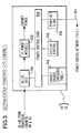
- FIG. 2 is a block diagram of a typical processor type cabinet and its connection to the power control network.
- FIG. 3 shows a "dependently-powered" input/output cabinet in block diagram 4 and its connection to the power control network.
- FIG. 4 is a block diagram showing an "independently-powered" cabinet and its connection to the power control network.
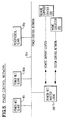
- FIG. 5 is a basic block diagram of the power control network showing the central power net master logic unit connected to control various power net slave logic units in this system.
- FIG. 6 is a block diagram showing the interconnection between the master logic unit and the slave logic units in the system.
- FIG. 7 is a block diagram of a typical power slave logic unit.
- FIG. 8 is a block diagram of the master network power logic unit showing the interconnections to the other parts of the system network.
- FIG. 9 is a block diagram of the peripheral power slave logic unit showing its connection to a peripheral cabinet and to the power control network of FIG. 5.
- FIG. 10 is a schematic diagram showing the protocol used for communication between master and slave units and additionally the byte format used.
- FIG. 11 is a flow diagram which summarizes the protocol activity for the master power network logic unit.
- FIG. 12 is a flow diagram which summarizes the protocol activity of the slave power control logic unit.
- This subsystem relates to a computer network and system which interconnects the following type of cabinets:
- a “dependently-powered” cabinet is a cabinet which derives its AC power and its high voltage input DC power from another cabinet (other than itself) -- in this case the other cabinet is called the "processor cabinet". Thus, the "dependently-powered" cabinet must be physically attached to the source cabinet.
- An "independently-powered" cabinet is a cabinet which has its own AC power Source. It may, therefore, be considered as a "free-standing" unit.
- FIG. 1 indicates a block diagram of the network power control subsystem 10. Shown therein are a dependent power I/O cabinet 20 and 30, in addition to two processor cabinets 40 and 50. Additionally connected to the power control network are the independent power I/O cabinets 60 and 70.
- FIG. 2 shows the power components of processor cabinets 40 and 50 which were shown in FIG. 1.
- the power energization of the processor cabinets 40 and 50 is controlled by the power control card 80 shown in FIG. 2.
- the power control card 80 is controlled by a "system operator" through the cabinet control circuits via an "operator panel” 44, and by the operating maintenance personnel who work through the control display 45 (maintenance switches and indicators) within the processor cabinet.
- the power control card 80 additionally monitors the cabinet environmental conditions such as over-temperature and cooling air-loss.
- the state of the cabinet power is further controlled by the power control network (PCN) through a card called the Power Net Slave Card 90.
- the processor cabinet (40, 50) also provides an AC power module 41 and a DC power module 43 for providing a high voltage DC to the attached-dependently-powered cabinets such as 20, 30.
- FIG. 3 illustrates the power components involved in the "dependently-powered cabinets such as 20 and 30 of FIG. 1.
- the power for these "dependently-powered" cabinets is controlled by the power control card 80 d .
- This power control card 80 d is controlled by a system operator (operating technician) through the cabinet control circuits and operator panel 44 d , and also by the operating maintenance personnel through the control display 45 d (via maintenance switches and indicators) inside the cabinet.
- the power control card 80 d also is used to monitor the cabinet environmental conditions such as over-temperature and the cooling air-loss.
- the power in the dependently powered I/O cabinet of FIG. 3 is also controlled by the power control network through the power net slave card 90 d .
- the "dependently-powered" I/O cabinet (such as 20 and 30) receive their AC and their high voltage DC input voltage from the attached processor cabinets such as 40 and 50 of FIG. 1.
- FIG. 4 there is shown a block diagram of the various power components of the "independently-powered" cabinets such as 60 and 70 of FIG. 1.
- the power for these independently-powered cabinets is controlled by the power control card 80 i .
- the power control card 80 i is controlled by a "system operator” through the cabinet control circuits and operator panel 44 i ; and also by the operating maintenance personnel through the control display 45 i (via maintenance switches and indicators inside the cabinet).
- the power control card 80 i also monitors the environmental conditions in the cabinet such as over-temperature or the loss of "air”.
- the cabinet power of the independently-powered cabinet of FIG. 4 is also controlled by the power control network through the power net slave card 90 i .
- the "independently-powered" I/O cabinets contain two I/O backplanes which are referred to as backplane A, 70 a , and also backplane B, 70 b , in addition to two interface panels described hereinafter.
- the DC power to each backplane is separately controlled.
- the DC power to both interface panels will be supplied the same as on backplane A, 70 a .
- the operator panel 44 i will provide separate controls for each backplane.
- the power control network (PCN) will also provide separate controls for each of the backplanes 70 a and 70 b .
- each backplane The DC power to each backplane is controlled separately.
- the operator panel 44 i will provide separate controls for each backplane and also the power control network connections 95 n shown in FIG. 4 will provide separate controls for each backplane.
- the independently-powered cabinets will have their own AC power source and therefore may be considered as "free standing”.
- the "independently-powered" memory cabinet may provide a remote support interface adapter. This adapter adds the power net master logic card to the cabinet as discussed hereinafter.
- PCN Power Control Network
- a Power Control Network (PCN, FIGS. 1 and 5, via 95 n ) connects all system cabinets. This allows a "SINGLE-POINT" of on-site operator control of the entire system of many cabinets. That is, the on-site operator need only depress a single power-on or power-off switch to control the entire system.
- the PCN provides total "power control" from an external remote support center 300 via telephone connection.
- the integrated PCN system only a single remote connection is needed to drive the entire system.
- the PCN provides a number of system failures and status monitoring functions and system maintenance controls. These functions are described in paragraphs that follow.
- the PCN allows the capability for an UNATTENDED site, that is, no local system operator is required. All system power controls, failure condition monitoring, and maintenance controls are available via the PCN to the remote center, 300.
- the PCN is specifically implemented through power net slave cards contained in each system cabinet and interconnected to the PCN.
- Each slave card is "always" powered, that is, is powered if the AC breaker for its cabinet is on.
- the slave within a cabinet is powered whether the cabinet operating DC power is on or not.
- the power net master logic card 100 of FIG. 8, which is part of the before mentioned remote support interface adapter (contained within an independently-powered memory cabinet), drives the Power Control Network and therefore all the power net slaves.
- the master logic unit 100 provides the central hub between the power control functions (Power Control Network), the remote support center (300) telephone connection and the system maintenance (200, FIG. 8) subsystem.
- the master card 100 is also "always" powered.
- the Operator Control Panels 44, 44 d , 44 i , FIGS. 2, 3, 4, are accessible to the operator on the outside of the respective cabinets.
- the panels provide the following functions:
- PCN commands are actions to a cabinet driven by the PCN.
- PCN commands can only affect a cabinet when it is in "system” mode, described in paragraph A above.
- PCN status is information about the cabinet returned over the PCN.
- PCN status is available in either "system” or "cabinet" local modes.
- the PCN functions are selected separately for each backplane.
- the PCN (Power Control Network) functions are:
- the PCN shown in FIGS. 5 and 6 is serially routed, two-wire, twisted-pair.
- the PCN circuit uses RS422 standard differential drivers and receivers (FIG. 6).
- Connected on the PCN will be numerous power net slaves and peripheral slaves and one power net master.
- the total number of connections is 64.
- the maximum transfer rate may reach 10K bits/second.
- FIG. 6 shows the connection of the RS422 drivers and receivers for slave cards and the master card. Also shown is the network termination resistors of 120 and 470 ohms.
- Each slave and master card provides two PCN (Power Control Network) connectors.
- PCN Power Control Network
- One connector receives the PCN cable from the previous unit and the other connector sends the PCN cable to the next unit. The PCN is thus serially routed.
- the PCN cable is a simple, inexpensive, twisted-pair cable.
- the PCN cables For PCN connections to non-attached cabinets, the PCN cables first are routed through interface panel cards in an I/O cabinet through RFI shielded cable into the non-attached cabinet.
- FIG. 7 shows a block diagram for a power net slave card.
- the diagram shows the controlling microprocessor 92 and the address switches 94 which give each cabinet an unique PCN address.
- Each slave has two parallel connecting ports 96, 97 to the power control cards of its cabinet.
- the slave also provides, via circuit 98, clock select or other signals and connects the RS422 interface to the PCN network itself.
- FIG. 8 shows the power net master logic unit 100 card block diagram
- FIG. 9 shows a peripheral-slave card block diagram. This slave can control only the power-on and power-off of a peripheral cabinet (disk pack controller).
- the power network slave logic shows a logic card connected between the power control circuits of a cabinet and the power control network.
- a major element of the slave logic card is a microprocessor such as an 8748 chip which contains internal program PROM and internal RAM.
- a typical chip of this designation is manufactured by Intel Corporation, whose address is 3065 Bowers Avenue, Santa Clara, California, and wherein this chip is described in a publication entitled "Microcontroller User's Manual", Order #210359-001, copyright 1982, and published by Intel Corporation, Literature Dept. SU3-3, of 3065 Bowers Avenue, Santa Clara, California.
- Each slave logic unit has a unique address which is set within the card by means of switches shown as element 94, address switches, in FIG. 7.
- the slave logic is connected to the power control network of FIG. 5 using the circuits shown in FIG. 6, which are RS422 receiver and driver chips.
- the RS422 receiver and driver chips are those such as typically manufactured by Advanced Micro Devices Company of 901 Thompson Place, (P.0. Box 453), Sunnyvale, California. These circuits are described in a publication entitled "Bipolar Microprocessor Logic & Interface Data Book" published by Advanced Micro Devices Company, copyright 1983.
- the power network slave logic in FIG. 7 has two ports designated as port A interface 96 and port B interface 97. These interfaces connect to the power control circuits within each of the cabinets such, for example, as power control card 80 of FIG. 2, power control card 80 d of FIG. 3, and power control card 80 i of FIG. 4.
- the signals to and from the port A96 and port B97 are described hereinafter.
- the power network slave logic unit 90 has four output signals (shown in FIG. 7 at the extreme right side) which may be activated or deactivated under the control of commands sent over the power control network. Thus, these four output signals may be used in cabinets containing a DPM (dual port memory), or for independent memory cabinets, in order to select the source for the DPM clocks. These four signals are individually controlled, raised or lowered, by commands from over the power net from the power net master logic unit 100 of FIG. 5.
- DPM dual port memory
- TTL transistor type logic
- the Select Circuits 98 of FIG. 7 use the inverter-buffer chips to provide a signal from the slave logic over a coaxial cable over to the DPM (Dual Port Memory) back plane.
- the power network slave logic unit 90 requires the use of control signals or "always power" from the cabinet in which it resides.
- Two on-board indicators and one switch are used to control each of the power network slave logic units 90, 90 i , 90 d , 90 p .
- a push-button switch (the re-set switch) is used to initialize the slave logic to run its own “self-test”. This is the same function that occurs at slave power-up time.
- One indicator (self-test) is "on” when the slave self-test program is in operation. If a self-test error occurs, this indicator will remain "on”.
- the second indicator (NET ERROR) is "on” whenever the slave logic detects a "NET" problem while the slave is communicating on "NET".
- NET errors include a framing error (too few or too many discs), a parity error, a NET protocol error, and an invalid command.
- the "NET ERROR” indicator will be deactivated when a "good" net communication to the slave logic unit occurs.
- FIG. 8 A block diagram of the power network master logic is shown in FIG. 8.
- the power network master logic 100 of FIG. 8 is housed in an independently-powered memory cabinet within the system, such as cabinet 70 of FIG. 1.
- the power network master logic will require power from this cabinet.
- the master logic 100 is the controlling device on the power control network of FIG. 5. It initiates all communications over the network; and thus, all communications over the network are effectuated between the master 100 and a slave logic unit such as 90. There is only one "active" master logic unit, such as 100, which may be connected to the power control network of FIG. 5 at any given time.
- the network master logic 100 also interfaces to the Maintenance Subsystem (200 shown in FIG. 8) through the System Control Network shown in FIG. 5. Also, as indicated in FIG. 5, the power network master logic is the single point of connection of the system to a Remote Support Center (RSC, 300 in FIGS. 5 and 8).
- RSC Remote Support Center
- FIG. 8 also shows the connections to the Remote Support Center 300 and also to the power control network of FIG. 5.
- the power network master logic unit 100 is provided with a microprocessor 100 u to which are connected a PROM 100 m1 and EEPROM 100 m2 in addition to a RAM unit 100 a .
- a power control interface 100 p connects the microprocessor to the power control network and a remote support interface 100 r connects the microprocessor to the remote support center 300.
- a time of day circuit 100 t with battery back-up provides time signals for the unit.
- the power network master logic unit 100 of FIG. 8 provides a central interconnection point for the power control network of FIG. 5, in addition to the system control network which is connected through the interface 100 s . It is also the central interconnection point for the remote support center interface (remote diagnostic) of element 100 r .
- the power network master logic unit 100 as the master unit for the power network, controls all the actions on this network.
- any multi-processor system there may be only one "active" power network master logic unit. Since, however, this unit is of considerable importance to the system operation and maintenance, there is generally provided a spare power network master logic unit, even though a failure in the power subsystem will not affect the operation of the overall processing unit.
- the microprocessor 100 u (Intel 8088) of FIG. 8 may be set to run at 8 megahertz. It executes its code out of the 32 K bytes of PROM 100 m1 .
- the 8 K bytes of RAM 100 a are used for data buffers and for operating stacks.
- the 256 bytes of electrically erasable PROM 100 m2 are used to store configuration-dependent option flags.
- the time of day circuit 100 t is backed up by a battery for use during times of power failure. Six indicators and five switches are provided on the master logic unit 100 for maintenance of the master card itself.
- Peripheral Slave Power Control Adaptor Peripheral Slave Power Control Adaptor
- the power control network may include peripheral devices which are provided with a peripheral slave power control adaptor 90 p .
- FIG. 9 shows a block diagram of such a peripheral slave power control adaptor 90 p .
- a microprocessor 92 p which connects to a peripheral power control driver circuit 95 p having connections to the peripheral cabinet.
- address switches 94 p which provide an input to the microprocessor 92 p , and also a driver-receiver circuit 99 p which connects to the power control network of FIG. 5.
- the peripheral slave power control adaptor such as 90 p of FIG. 9, is located in an interface panel within the I/O cabinets such as 60 and 70 of FIG. 1, and also in cabinets 20 and 30 of FIG. 1.
- the peripheral slave power control adaptor 90 p of FIG. 9 connects between the power control network of FIG. 5 and any selected system peripheral cabinets. There are certain cabinet types to which the peripheral slave power control adaptor may be connected. These are:
- the peripheral slave adaptor 90 p provides only "power-on” and “power-off” control for these cabinets.
- the peripheral slave adaptor 90 p is logically a simple slave unit.
- the microprocessor 92 p may use an 8748 microprocessor chip (previously described) and interfaces to the power control network with the RS422 driver receiver chip designated 99 p .
- the peripheral slave logic of FIG. 9 differs from the internal power slave logic unit of FIG. 7 in that, in place of the port A and port B interfaces (96, 97) of FIG. 7, the "peripheral" slave logic has special driver circuits 95 p in order to control the "on/off" state of the connecting peripheral cabinets.
- FIG. 10 is an illustrative drawing showing the particular sequence of events over the network.
- the master logic unit 100 first sends the Address byte shown in line 1 of the drawing of FIG. 10. This Address is the address of the desired slave unit to be addressed. Each slave unit receives and evaluates the Address received and then the appropriate slave unit will return its Address to the master power unit 100.
- the master logic unit 100 will send a Command byte (shown in line 3) to the previously addressed slave unit, such as 90 of FIG. 7.
- the slave unit such as 90, then returns the Command byte to the master as illustrated in line 4 of FIG. 10.
- the slave has received the Command byte, it returns it to the master and if the byte received by the master logic unit 100 then agrees with the byte that it (master unit) had previously sent, the master logic unit 100 re-sends the Command byte again, as illustrated in line 5 showing the Command byte being re-sent from master to slave.
- the slave logic unit 90 will decode and execute the Command received. The slave will then return its General Status byte to the master as seen in line 6 of FIG. 10.
- the specified Status byte is returned instead of the General Status byte.
- the General Status byte which is returned to the slave logic unit 90 will not reflect the new power state of the cabinet involved. It will show the status of the cabinet "prior to" the command. To check the new state of the cabinet involved, a Send Status Command will be sent about 15 seconds later after the power on/off Command was sent.
- FIG. 10 indicates the general network flow for the master power logic unit 100 as it polls the various slaves 90 over the network. After the master logic unit 100 sends an Address, it waits for the return of the addressed slave unit's address. If an incorrect address is returned from the slave logic unit 90, the master power logic unit 100 will re-try the expected address. It will try the desired address three times before it assumes that the Address slave logic unit 90 may be "bad".
- the master power logic unit 100 also does the same re-try/time-out procedures for the Command bytes.
- the master power logic unit 100 finds an "improperly" responding slave logic unit 90, while polling, it will report the condition to the maintenance subsystem 200 over the system control network connected as shown in FIG. 8.
- FIG. 10 also indicates the network byte format for the power network. As shown therein, there is one bit used for a start bit, then 8 bits are used for a data byte, then one bit is used for odd parity, and one bit is used as a stop bit.
- FIG. 11 shows a drawing of a flow chart showing the network flow for the master power control logic unit 100 which summarizes the various protocol steps used in FIG. 10 on lines 1-6.
- FIG. 12 is a flow chart diagram which summarizes the protocol involved for the slave power logic unit in the system operation.
- Table II shows one scheme on which Addresses may be provided for the processor cabinets, the independent memory cabinets, the I/O cabinets, and the various peripheral cabinets, whereby the power control network system may address and communicate with specific cabinets in order to provide Command and Control functions in the power network system.
- the PCN Since the PCN has "great power" over a system, that is, it can turn off a system, it is necessary that the network protocol be fault tolerant and reliable.
- the PCN protocol was designed with several layers of redundancy and checking.
- FIG. 10 shows the PCN byte format.
- the PCN byte contains one start bit, eight bits of information (data byte), one odd-parity bit, and one stop bit.
- FIG. 10 also shows the PCN message transfer protocol between the power net master card and a slave card. All transfers on the PCN are initiated by the master. All transactions follow the steps described below:
- FIG. 11 gives the master flow (less steps a - d).
- FIG. 12 gives the slave flow.
Landscapes
- Engineering & Computer Science (AREA)
- Theoretical Computer Science (AREA)
- Physics & Mathematics (AREA)
- General Engineering & Computer Science (AREA)
- General Physics & Mathematics (AREA)
- Power Sources (AREA)
- Communication Control (AREA)
Claims (5)
- Réseau de modules numériques interconnectés (20, 30, 40, 50, 60, 70) dans lequel chaque module comporte une unité logique de puissance (90), esclave, associée, un moyen de commutation de commande de puissance, interne (80) et un moyen d'alimentation interne (41, 43) de puissance, chacun des moyens de commutation de commande de puissance pouvant exécuter les données d'instruction de commande de puissance reçues de l'unité logique de puissance esclave, associée qui est reliée à une unité logique de puissance, maître (100), réseau caractérisé en ce que l'unité logique de puissance esclave, associée, comprend un microprocesseur (92) pour recevoir et enregistrer les données d'adresse et les données d'instruction de commande de puissance de l'unité logique de puissance maître, le processeur étant programmé pour distinguer les données d'adresse des données d'instruction par l'intermédiaire d'un bit de drapeau attaché aux données, d'enregistrer une copie de la première donnée reçue, d'envoyer une copie de cette première donnée reçue en retour à l'unité maître pour être vérifiée par cette unité maître, à recevoir une seconde copie de la première donnée reçue et comparer cette seconde copie à la première donnée reçue et accepter et utiliser la première donnée reçue si la seconde copie et la première donnée reçue se correspondent, et en ce que l'unité logique de puissance, maître, est branchée pour détecter l'état de puissance de chacun des modules et pour transmettre la donnée d'instruction de commande de régulation et de commutation de l'état de puissance d'un module adressé de manière sélective ou de modules ou de tous les modules, cette unité maître comprenant un moyen (100) pour générer des données d'instruction de commande de puissance en réponse aux instructions de l'opérateur humain, un moyen pour générer un bit de drapeau pour distinguer les données d'adresse des données d'instruction, un moyen pour transmettre et enregistrer une première copie de la première donnée transmise, cette donnée transmise étant envoyée à l'unité esclave, un moyen pour recevoir une seconde copie de l'unité esclave, de la première donnée transmise, pour la comparaison avec la première copie de la première donnée transmise, un moyen pour générer une seconde transmission de la première donnée transmise vers l'unité esclave si la première donnée transmise et la seconde copie reçue se correspondent.
- Réseau selon la revendication 1, caractérisé en ce que l'unité logique de puissance, esclave, comporte un moyen de réglage manuel (94) pour définir une adresse unique pour l'identification de l'unité maître.
- Réseau selon la revendication 1 ou la revendication 2, caractérisé en ce que l'unité logique esclave comprend un moyen pour générer un octet d'état, pour le transmettre à l'unité maître, pour transférer les données concernant la condition de puissance et la condition de travail du module dans lequel se trouve l'unité esclave, l'octet d'état étant généré à la fin de l'exécution de n'importe quel ordre par l'unité esclave.
- Procédé de commande d'un réseau de modules numériques interconnectés (20, 30, 40, 50, 60, 70), chaque module comprenant un moyen de commutation de commande de puissance interne (80) et un moyen d'alimentation de puissance interne (41, 43) et chacun des moyens de commutation de commande de puissance peut exécuter des instructions de commande d'état de puissance reçues d'une unité logique de puissance esclave, associée (90) qui est reliée à une unité logique de puissance maître (100), procédé caractérisé par les étapes suivantes : on détecte la donnée d'état de puissance de chacun des modules par l'unité logique de puissance maître ; on génère une première trame de données avec un bit de départ, un octet de données de l'adresse de l'unité esclave comprenant un bit de drapeau pour identifier la donnée comme étant une donnée d'adresse, un bit de parité et un bit d'arrêt pour la transmission à l'unité esclave ; on retransmet par l'unité esclave vers l'unité maître, une première copie de la première trame de données ; on compare par l'unité maître la première trame avec la première copie de la première trame ; on autorise l'unité maître à générer une instruction de commande de puissance si la première trame et la première copie se correspondent, cette instruction contenant un bit de drapeau et un bit de parité ; on génère avec l'unité maître vers l'unité esclave, une seconde trame qui fournit des données d'ordre d'instruction à la place de données d'adresse et un bit de drapeau pour identifier les données comme données d'instruction ; on retransmet par l'unité esclave vers l'unité maître, une première copie de la seconde trame ; on compare par l'unité maître, la seconde trame à la première copie de cette seconde trame ; on transmet par l'unité maître vers l'unité esclave une seconde copie de la seconde trame ; on compare par l'unité esclave la première copie de la seconde trame à la seconde copie de la seconde trame ; on autorise l'unité esclave à exécuter la donnée d'instruction de la seconde trame pour réguler et pour commuter la donnée d'état de puissance d'un module adressé sélectivement ou de modules ou de tous les modules si la première copie de la seconde trame correspond à la seconde copie de la seconde trame.
- Procédé selon la revendication 4, caractérisé en ce qu'on transmet par l'unité esclave à l'unité maître, les données d'état de puissance pour informer l'unité maître des conditions de puissance du module dans lequel se trouve l'unité esclave.
Applications Claiming Priority (2)
| Application Number | Priority Date | Filing Date | Title |
|---|---|---|---|
| US06/654,080 US4635195A (en) | 1984-09-25 | 1984-09-25 | Power control network using reliable communications protocol |
| US654080 | 1984-09-25 |
Publications (3)
| Publication Number | Publication Date |
|---|---|
| EP0176342A2 EP0176342A2 (fr) | 1986-04-02 |
| EP0176342A3 EP0176342A3 (en) | 1988-03-30 |
| EP0176342B1 true EP0176342B1 (fr) | 1991-06-19 |
Family
ID=24623360
Family Applications (1)
| Application Number | Title | Priority Date | Filing Date |
|---|---|---|---|
| EP85306768A Expired EP0176342B1 (fr) | 1984-09-25 | 1985-09-24 | Réseau pour contrôler l'alimentation utilisant un protocole de communication fiable |
Country Status (6)
| Country | Link |
|---|---|
| US (1) | US4635195A (fr) |
| EP (1) | EP0176342B1 (fr) |
| JP (1) | JPS62500269A (fr) |
| CA (1) | CA1243410A (fr) |
| DE (1) | DE3583273D1 (fr) |
| WO (1) | WO1986002185A1 (fr) |
Families Citing this family (39)
| Publication number | Priority date | Publication date | Assignee | Title |
|---|---|---|---|---|
| DE3526364A1 (de) * | 1985-07-19 | 1987-01-22 | Siemens Ag | Schaltungsanordnung zur netzunabhaengigen spannungsversorgung einer an ein busnetzwerk angeschlossenen verteileinrichtung fuer datenstationen |
| US5007013A (en) * | 1986-04-01 | 1991-04-09 | Westinghouse Electric Corp. | Bidirectional communication and control network with programmable microcontroller interfacing digital ICS and controlled product |
| JP2510696B2 (ja) * | 1988-09-26 | 1996-06-26 | 株式会社日立製作所 | 計算機システム自動運転制御方式 |
| JP2694993B2 (ja) * | 1989-02-22 | 1997-12-24 | 株式会社日立製作所 | 電力用信号処理システムおよびディジタル保護リレー装置 |
| US5151855A (en) * | 1989-10-19 | 1992-09-29 | Saturn Corporation | Multiple microprocessor single power supply system shutdown |
| EP0513206B1 (fr) * | 1990-01-30 | 1995-04-12 | Johnson Service Company | Systeme de gestion d'unites interconnectees en reseau |
| US5396635A (en) * | 1990-06-01 | 1995-03-07 | Vadem Corporation | Power conservation apparatus having multiple power reduction levels dependent upon the activity of the computer system |
| US5347167A (en) * | 1990-08-09 | 1994-09-13 | Sophisticated Circuits, Inc. | Power controller using keyboard and computer interface |
| JPH0727445B2 (ja) * | 1990-09-04 | 1995-03-29 | インターナショナル・ビジネス・マシーンズ・コーポレイション | コンピュータプロセッサ動作用ユーザインターフェイス |
| KR960010478B1 (ko) * | 1990-11-14 | 1996-08-01 | 캐논 가부시끼가이샤 | 무선통신으로 접속되는 정보처리 장치 및 방법 |
| US5117430A (en) | 1991-02-08 | 1992-05-26 | International Business Machines Corporation | Apparatus and method for communicating between nodes in a network |
| US5455959A (en) * | 1992-03-02 | 1995-10-03 | Alcatel Network Systems, Inc. | System for collecting from masters information independently collected from associated slaves in shelves of a telecommunications terminal |
| US6230273B1 (en) * | 1993-08-09 | 2001-05-08 | Ncr Corporation | Hardware and software controlled on/off circuit for computers |
| DE69432661T2 (de) * | 1994-01-14 | 2004-03-25 | Sun Microsystems, Inc., Mountain View | Intelligenter Schalter |
| US5809313A (en) * | 1995-07-06 | 1998-09-15 | Sun Microsystems, Inc. | Method and apparatus for powering-on a computer-based system via a network interface |
| CA2196402A1 (fr) * | 1996-02-09 | 1997-08-10 | Robert L. Smith | Commutateur intelligent |
| US6047378A (en) * | 1997-09-29 | 2000-04-04 | International Business Machines Corporation | Wake multiple over LAN |
| US6832120B1 (en) | 1998-05-15 | 2004-12-14 | Tridium, Inc. | System and methods for object-oriented control of diverse electromechanical systems using a computer network |
| EP0964336B1 (fr) * | 1998-06-01 | 2003-01-15 | Seiko Epson Corporation | Méthode de surveillance de l'état de l'alimentation dans un périphérique connecté à un ordinateur principal |
| US6460005B1 (en) * | 2000-08-10 | 2002-10-01 | International Business Machines Corporation | Apparatus and method for monitoring environmental conditions in a computing device |
| US7058826B2 (en) | 2000-09-27 | 2006-06-06 | Amphus, Inc. | System, architecture, and method for logical server and other network devices in a dynamically configurable multi-server network environment |
| US7032119B2 (en) * | 2000-09-27 | 2006-04-18 | Amphus, Inc. | Dynamic power and workload management for multi-server system |
| USRE40866E1 (en) | 2000-09-27 | 2009-08-04 | Huron Ip Llc | System, method, and architecture for dynamic server power management and dynamic workload management for multiserver environment |
| US7822967B2 (en) * | 2000-09-27 | 2010-10-26 | Huron Ip Llc | Apparatus, architecture, and method for integrated modular server system providing dynamically power-managed and work-load managed network devices |
| US7552350B2 (en) | 2000-09-27 | 2009-06-23 | Huron Ip Llc | System and method for activity or event base dynamic energy conserving server reconfiguration |
| US20030196126A1 (en) * | 2002-04-11 | 2003-10-16 | Fung Henry T. | System, method, and architecture for dynamic server power management and dynamic workload management for multi-server environment |
| US20060248360A1 (en) * | 2001-05-18 | 2006-11-02 | Fung Henry T | Multi-server and multi-CPU power management system and method |
| JP4338354B2 (ja) * | 2001-05-21 | 2009-10-07 | オムロン株式会社 | スレーブ |
| JP3914036B2 (ja) * | 2001-11-19 | 2007-05-16 | 富士通株式会社 | Pon通信の親機及び子機 |
| US7444532B2 (en) * | 2001-12-03 | 2008-10-28 | Dell Products L.P. | System and method for autonomous power sequencing |
| WO2003071444A1 (fr) * | 2002-02-15 | 2003-08-28 | Tridium, Inc. | Modele de composant destine a la commande temps reel d'un systeme |
| JP2005254621A (ja) * | 2004-03-11 | 2005-09-22 | Seiko Epson Corp | 電源制御装置及び電源制御方法 |
| US7388248B2 (en) * | 2004-09-01 | 2008-06-17 | Micron Technology, Inc. | Dielectric relaxation memory |
| US20090082880A1 (en) * | 2007-09-20 | 2009-03-26 | Tridium Inc. | Wireless device for a building control system |
| JP5457273B2 (ja) | 2010-05-31 | 2014-04-02 | 富士通コンポーネント株式会社 | 電源制御システム、電源制御システムの制御方法、電源制御装置及びプログラム |
| EP2452250B1 (fr) | 2010-07-08 | 2015-09-09 | Nec Corporation | Procédé de prise en charge de commande de puissance dans un réseau de communication |
| WO2013174751A2 (fr) * | 2012-05-21 | 2013-11-28 | E-Volo Gmbh | Procédé de commande d'un appareil volant sous forme d'un multicoptère et système de commande correspondant |
| JP6352672B2 (ja) | 2014-04-22 | 2018-07-04 | 富士通コンポーネント株式会社 | 制御装置及び通信システム |
| GB2528665B (en) * | 2014-07-25 | 2016-07-27 | Tokyo Electron Europe Ltd | Identification System |
Family Cites Families (9)
| Publication number | Priority date | Publication date | Assignee | Title |
|---|---|---|---|---|
| US3796994A (en) * | 1971-06-24 | 1974-03-12 | Edwards Co | Code communication system |
| US4070648A (en) * | 1976-06-18 | 1978-01-24 | Ncr Corporation | Computer to computer communication system |
| US4161718A (en) * | 1977-06-20 | 1979-07-17 | Motorola Israel Ltd. | Supervisory control system |
| JPS5418238A (en) * | 1977-07-12 | 1979-02-10 | Toshiba Corp | Automatic power supply throw-in device |
| JPS5813928B2 (ja) * | 1978-06-28 | 1983-03-16 | 株式会社東芝 | 計算機制御装置 |
| FR2497373B1 (fr) * | 1980-12-30 | 1986-09-05 | Bull Sa | Systeme d'alimentation microprogrammable pour systeme de traitement de donnees comportant un panneau de service destine aux operations de maintenance et procedes d'exploitation de ce panneau de service |
| JPS5814226A (ja) * | 1981-07-20 | 1983-01-27 | Usac Electronics Ind Co Ltd | 電子計算機の電源制御方式 |
| JPS5813928A (ja) * | 1981-07-20 | 1983-01-26 | Matsushita Electric Ind Co Ltd | 加熱調理器 |
| JPS58115508A (ja) * | 1981-12-29 | 1983-07-09 | Fujitsu Ltd | 電源制御装置 |
-
1984
- 1984-09-25 US US06/654,080 patent/US4635195A/en not_active Expired - Lifetime
-
1985
- 1985-09-24 JP JP60504435A patent/JPS62500269A/ja active Pending
- 1985-09-24 DE DE8585306768T patent/DE3583273D1/de not_active Expired - Lifetime
- 1985-09-24 EP EP85306768A patent/EP0176342B1/fr not_active Expired
- 1985-09-24 CA CA000491420A patent/CA1243410A/fr not_active Expired
- 1985-09-24 WO PCT/US1985/001819 patent/WO1986002185A1/fr not_active Ceased
Also Published As
| Publication number | Publication date |
|---|---|
| DE3583273D1 (de) | 1991-07-25 |
| CA1243410A (fr) | 1988-10-18 |
| EP0176342A2 (fr) | 1986-04-02 |
| JPS62500269A (ja) | 1987-01-29 |
| US4635195A (en) | 1987-01-06 |
| EP0176342A3 (en) | 1988-03-30 |
| WO1986002185A1 (fr) | 1986-04-10 |
Similar Documents
| Publication | Publication Date | Title |
|---|---|---|
| EP0176342B1 (fr) | Réseau pour contrôler l'alimentation utilisant un protocole de communication fiable | |
| EP0178642B1 (fr) | Réseau pour commander l'alimentation de multiples modules numériques | |
| US4663539A (en) | Local power switching control subsystem | |
| EP0147046B1 (fr) | Système de contrôleurs de communication tolérant des fautes | |
| US6275864B1 (en) | Matrix switch for a network management system | |
| US4747041A (en) | Automatic power control system which automatically activates and deactivates power to selected peripheral devices based upon system requirement | |
| US6952785B1 (en) | Methods and apparatus for powering a data communications port | |
| KR940006821B1 (ko) | 진단 시스템 | |
| US7039918B2 (en) | Service processor and system and method using a service processor | |
| US6202160B1 (en) | System for independent powering of a computer system | |
| US6134668A (en) | Method of selective independent powering of portion of computer system through remote interface from remote interface power supply | |
| US7076588B2 (en) | High speed multiple ported bus interface control | |
| AU768503B2 (en) | Fault tolerant virtual VMEbus backplane design | |
| US5115511A (en) | Arrangement for loading the parameters into active modules in a computer system | |
| JP2562547B2 (ja) | 一つのコンソールを中央処理装置と共有するシステム状態監視装置 | |
| EP0306855A2 (fr) | Agencement pour charger les paramètres dans des modules actifs d'un système ordinateur | |
| EP0400930A2 (fr) | Système d'opérations redondant en temps réel | |
| CN114857069A (zh) | 一种风扇冶具板 | |
| EP0325079A1 (fr) | Dispositif de commande à distance pour des adaptateurs de canal dans un système de traitement de données | |
| JPH06282518A (ja) | 情報処理装置 | |
| JPH05108210A (ja) | スレーブ情報処理装置 | |
| JPH05153667A (ja) | 遠隔監視制御システム |
Legal Events
| Date | Code | Title | Description |
|---|---|---|---|
| PUAI | Public reference made under article 153(3) epc to a published international application that has entered the european phase |
Free format text: ORIGINAL CODE: 0009012 |
|
| 17P | Request for examination filed |
Effective date: 19851001 |
|
| AK | Designated contracting states |
Kind code of ref document: A2 Designated state(s): DE FR GB NL |
|
| RAP1 | Party data changed (applicant data changed or rights of an application transferred) |
Owner name: UNISYS CORPORATION |
|
| PUAL | Search report despatched |
Free format text: ORIGINAL CODE: 0009013 |
|
| AK | Designated contracting states |
Kind code of ref document: A3 Designated state(s): DE FR GB NL |
|
| 17Q | First examination report despatched |
Effective date: 19891025 |
|
| GRAA | (expected) grant |
Free format text: ORIGINAL CODE: 0009210 |
|
| AK | Designated contracting states |
Kind code of ref document: B1 Designated state(s): DE FR GB NL |
|
| PG25 | Lapsed in a contracting state [announced via postgrant information from national office to epo] |
Ref country code: NL Effective date: 19910619 |
|
| ET | Fr: translation filed | ||
| REF | Corresponds to: |
Ref document number: 3583273 Country of ref document: DE Date of ref document: 19910725 |
|
| NLV1 | Nl: lapsed or annulled due to failure to fulfill the requirements of art. 29p and 29m of the patents act | ||
| PLBE | No opposition filed within time limit |
Free format text: ORIGINAL CODE: 0009261 |
|
| STAA | Information on the status of an ep patent application or granted ep patent |
Free format text: STATUS: NO OPPOSITION FILED WITHIN TIME LIMIT |
|
| 26N | No opposition filed | ||
| PGFP | Annual fee paid to national office [announced via postgrant information from national office to epo] |
Ref country code: FR Payment date: 19940908 Year of fee payment: 10 |
|
| PGFP | Annual fee paid to national office [announced via postgrant information from national office to epo] |
Ref country code: GB Payment date: 19950807 Year of fee payment: 11 |
|
| PGFP | Annual fee paid to national office [announced via postgrant information from national office to epo] |
Ref country code: DE Payment date: 19950928 Year of fee payment: 11 |
|
| PG25 | Lapsed in a contracting state [announced via postgrant information from national office to epo] |
Ref country code: FR Effective date: 19960531 |
|
| REG | Reference to a national code |
Ref country code: FR Ref legal event code: ST |
|
| PG25 | Lapsed in a contracting state [announced via postgrant information from national office to epo] |
Ref country code: GB Effective date: 19960924 |
|
| GBPC | Gb: european patent ceased through non-payment of renewal fee |
Effective date: 19960924 |
|
| PG25 | Lapsed in a contracting state [announced via postgrant information from national office to epo] |
Ref country code: DE Effective date: 19970603 |