EP0176408A1 - Verfahren und Messgerät zur akustischen Kontrolle eines mit einem Rohr ausgerüsteten Bohrlochs - Google Patents
Verfahren und Messgerät zur akustischen Kontrolle eines mit einem Rohr ausgerüsteten Bohrlochs Download PDFInfo
- Publication number
- EP0176408A1 EP0176408A1 EP85401716A EP85401716A EP0176408A1 EP 0176408 A1 EP0176408 A1 EP 0176408A1 EP 85401716 A EP85401716 A EP 85401716A EP 85401716 A EP85401716 A EP 85401716A EP 0176408 A1 EP0176408 A1 EP 0176408A1
- Authority
- EP
- European Patent Office
- Prior art keywords
- casing
- acoustic
- signals
- signal
- reflection signal
- Prior art date
- Legal status (The legal status is an assumption and is not a legal conclusion. Google has not performed a legal analysis and makes no representation as to the accuracy of the status listed.)
- Granted
Links
Images


Classifications
-
- G—PHYSICS
- G01—MEASURING; TESTING
- G01V—GEOPHYSICS; GRAVITATIONAL MEASUREMENTS; DETECTING MASSES OR OBJECTS; TAGS
- G01V1/00—Seismology; Seismic or acoustic prospecting or detecting
- G01V1/40—Seismology; Seismic or acoustic prospecting or detecting specially adapted for well-logging
- G01V1/44—Seismology; Seismic or acoustic prospecting or detecting specially adapted for well-logging using generators and receivers in the same well
-
- E—FIXED CONSTRUCTIONS
- E21—EARTH OR ROCK DRILLING; MINING
- E21B—EARTH OR ROCK DRILLING; OBTAINING OIL, GAS, WATER, SOLUBLE OR MELTABLE MATERIALS OR A SLURRY OF MINERALS FROM WELLS
- E21B47/00—Survey of boreholes or wells
- E21B47/005—Monitoring or checking of cementation quality or level
Definitions
- the invention relates to a method and a device for the acoustic inspection of a borehole provided with casing and passing through terrestrial formations. It relates more particularly to a method and a device, using an acoustic pulse technique, for forming signals respectively representative of one or more pieces of information relating to the casing and to the materials which surround it, while taking into account the effects due to the environment.
- the information relating to the casing and to the materials which surround it include in particular the quality of the cement bond with the casing, its thickness and the roughness of its interior wall.
- a casing is placed in the borehole, and cement is injected into the annular space formed by the casing and the wall of the borehole in order to avoid any communication. hydraulic between the different geological layers. To determine the possible existence of such harmful communications, measurements are made using a logging tool to determine the quality of the cement bond with the casing.
- the reverberation segment considered is chosen so as to be substantially representative of the acoustic reverberations between the walls of the casing.
- a rapid damping of the resonance in other words a low energy, indicates the presence of cement behind the casing, while a slow damping, therefore a high energy, indicates the absence of cement.
- a logging tool using such a technique is described in a Schlumberger commercial brochure entitled "Cement Evaluation Tool” and published in June 1983.
- the probe of this tool is centered in the casing. It includes eight transducers distributed helically at 45 ", so as to obtain good coverage of the periphery of the casing.
- the acoustic impulses are triggered sequentially. Receptions, also sequential, are analyzed and sent to the surface where they are treated.
- a ninth transducer also called reference transducer, is oriented along the axis of the casing towards a reflecting wall which is planar and disposed at a fixed distance from the reference transducer.
- the propagation time, through the fluid in situ, of the acoustic wave is determined in the time interval separating its emission from its reception, and we deduces the speed of propagation of the wave through the medium in question. From this propagation speed of the wave, it is possible to determine, for each of the eight transducers, an apparent radius of the casing. This radius is particularly interesting to know, because it allows in particular to detect a possible deformation of the casing and to monitor the centering of the probe in the casing so as to provide an indication of the validity and the quality of the recorded measurements.
- the object of the invention therefore relates to a method and a device for the acoustic inspection of a borehole provided with a casing in which the harmful effects discussed above are eliminated.
- a method for the acoustic inspection of a borehole provided with casing and traversing earth formations consisting in forming one or more signals representative respectively of one or more information relating to said casing and to the materials which surround it, from a first acoustic reflection signal obtained following the sending, through the medium present in the casing, of a first acoustic impulse directed, at a substantially normal incidence, towards a sector of the wall of the casing, further consists in correcting the first acoustic reflection signal using a second acoustic reflection signal obtained following the sending, through the same medium in presence, of a second pulse acoustics directed, at a substantially normal incidence, towards a reference reflector whose nominal characteristics are substantially similar to those of a casing sector and udie.
- the first and second locations are substantially the same distance from the casing and the reflector, respectively.
- the characteristics of the reflector include in particular the geometric characteristics, such as its thickness and its curvature.
- the information relating to the casing and the materials which surround it includes inter alia the quality of the cement bond with the casing, the roughness of the inner wall of the casing as well as its thickness.
- the distance between the front face of each of the measurement transducers and the outer wall of the casing is substantially equal to the distance between the front face of the reference transducer and the rear face of said reference reflector.
- the thickness and the curvature of the reference reflector are preferably substantially identical to that of the casing studied.
- said means for correcting said first acoustic reflection signal include means for making the ratio of a magnitude of the signal, respectively measured in one or more windows of one of the two acoustic reflection signals, to the same magnitude respectively measured in the corresponding windows of the other two acoustic reflection signals.
- the magnitude mentioned above notably includes the amplitude, the energy, the frequency and the phase of the signal.
- the acoustic logging device for studying the quality of the cement comprises a bottom device 10 suspended in a borehole 11 at the end of a multi-conductor cable 12 and immersed in a surrounding medium M.
- the borehole which crosses the formations 13 is provided with casing 14.
- Cement 15 occupies the annular space delimited by the casing and the formations studied.
- This logging device includes the basic characteristics of that described in French patent 78 20515, mentioned above.
- the downhole apparatus 10 is an elongated body which comprises a probe 16, upper 17 and lower 18 centralizers intended to hold the probe 16 in the axis of the casing 14, an acoustic compensation section 22, a hydraulic compensation section 32 and an electronic section 19.
- the probe 16 is equipped with eight transducers acousti- q ues T 1 to T 8 (generally designated 20) and disposed helically so as to enable the investigation of eight casing sectors regularly distributed over its periphery.
- the angular position of a transducer is deduced from the previous one by a rotation of 45 ° around the axis of the probe.
- Other arrangements are obviously possible with different numbers of transducers and / or different distributions all around the probe, without departing from the scope of the invention.
- the centralizers 18 and 19 are of the known type, in which means (not shown) are provided allowing electrical and / or hydraulic connections between the upper part and the lower part of each of the centralizers.
- Section 32 is of the known type in which the fluid of the hydraulic circuits of the downhole apparatus 10 is subjected to the pressure of the surrounding medium M, namely the hydrostatic pressure of the well, so as to avoid excessively high differential pressures on sensitive parts of the probe, such as transducers.
- Section 22 called the acoustic compensation section, has a recess 23 open to the fluid M present.
- a ninth transducer T9 called reference transducer and similar to transducers T1 to T8, emits acoustic waves through the recess 23 along an axis substantially coincident with the axis of the probe 16 to a reflector 24 placed in the recess 23
- Each transducer Tn (T1 to T9) is controlled to emit short duration acoustic pulses whose spectrum covers the frequency range between 300 KHz and 600 KHz, the average frequency being approximately 500 KHz.
- the emission direction of the transducers T1 to T8 is radial, while that of T9 is longitudinal.
- Each transmitted pulse is reflected by the different interfaces it encounters, namely the casing 14 for T1 to T8 and the reflector 24 for T9, thus giving an echo signal detected by the same transducer.
- the detected signals are transmitted, by appropriate wiring (not shown) passing through the centralizer 17, to the electronic section 19, in which they are sampled at a chosen rate, put in digital form, then multiplexed and finally transmitted to the surface by a MODEM (not shown) connected to the cable conductors 12.
- the conductors of cable 12 are connected to an acquisition system 25 comprising a MODEM for decoding the information transmitted and a demultiplexer.
- the signals are then stored in a memory 26.
- the latter is connected to a computer 27 capable of carrying out a series of processing steps at each level of depth. These steps will be developed later.
- the signals representative of the depth of the apparatus 10 are generated by a displacement detector comprising a pulse generator 28 controlled by a wheel 29 in tangential support on the cable 12.
- the pulse generator 28 delivers a pulse each time the cable 12 has moved one unit in length.
- the processing of the computer 27 supplies a first set of output signals to a magnetic recorder 30 which records them in digital form, level by level, on a magnetic tape.
- This magnetic recording contains in particular the signals delivered by the transducers T1 to T9 and therefore allows subsequent processing of the data.
- the computer 27 also supplies, for each level, a second set of output signals to an optical recorder 31 which makes a graphic recording on a film, for example of the type described in French patent 80.20890 (Publication No. 2,491,123) .
- the acoustic compensation section 22 comprises a body 33, connected at its upper part to the probe 16 and at its lower part to the centralizer 18.
- the upper connection and the lower connection are provided respectively by the nuts 34 and 35, each of the nuts being formed from two half rings (not shown) for mounting reasons.
- the nut 34 is mounted to rotate freely on a groove of the probe 16, the friction surface between the two parts being isolated from the fluid M by an O-ring 36 and lubricated through a greaser 37.
- the nut 35 is mounted to rotate freely on a groove of the body 33, the friction surface between the two parts being isolated from the external fluid by an O-ring 38 and lubricated through a greaser 39.
- An alignment key 40 is provided so as to prevent the rotation of the body 33 relative to the probe 16.
- a second key 41 prevents the rotation of the body 33 relative to the centralizer 18.
- the seal between the probe 16 and the body 33, and the body 33 and the centralizer 18, is provided respectively by the O-rings 42 and 43.
- the reference transducer T9 is fixed in its housing 44 by means of a pin 45.
- Two electrical conductors 61, 62 placed in the hydraulic conduit 63 of the probe 16 connect the transducer T9 to the electronic section 19.
- the housing 44 located in the chamber 49 of the probe 16, is held on the end face of the probe 16 by means of three similar screws 46 through three tabs 47 for fixing at 120 °.
- the seal between the body 33 and the housing 44 is ensured by the O-ring 48.
- the chamber 49 is filled with hydraulic fluid and communicates with the duct 51 of the centralizer 18 via the duct 50 of the body 33.
- the body 33 has a recess 23 open to the fluid M outside the probe.
- Each of the two opposite faces (54,55) of the recess 23 comprise a set of slides (56,57) parallel to each other and perpendicular to the axis of the section 33; these, nine in number in the embodiment described, are used for positioning the selected reflector 24. This selection is made according to the diameter of the casing to be studied and its thickness.
- Each of the slides corresponds to a given nominal diameter of casing.
- the table which follows gives an illustrative but nonlimiting example of the correspondences between each of the slides and each of the diameters of casing ordinarily used in the petroleum industry.
- Each of these slides therefore corresponds to a series of possible reflectors 24 having the same curvature, namely that of the casing to be studied, and of different thicknesses between them.
- the shape of the reflectors corresponds to a cylinder section of the casing studied.
- slide E there are 8 different reflectors all having the same curvature, namely that of the casing of 178 mm, and each having a thickness respectively equal to the thickness of the eight different casings of 178 mm in diameter ordinarily encountered. in the petroleum industry.
- the total number of different reflectors is approximately fifty.
- the reflectors are made of a material having acoustic characteristics similar to those of the casing; the present embodiment uses stainless steel.
- the reflector 24 is provided with two lateral grooves which allow the introduction and the positioning of the reflector in the corresponding slide. Once positioned, the reflector 24 is locked in place by means of a screw 52 which comes to bear on the blade 53 which has a certain elasticity.
- the acoustic compensation section 32 is provided with a deflector 58 whose objective is to channel a part of the fluid on the front surface of the reflector 24, so that the fluid present between the reference transducer T9 and the reflector 24 is constantly renewed during the movement of the bottom apparatus 10.
- This circulation of fluid consequently prevents the agglomeration of debris inside the recess 23 and the formation of a deposit of material solid on the surface of the reflector 24, which would alter the information extracted from the reference acoustic signal thus obtained; in addition, it ensures the homogeneity of the characteristics of the fluid.
- the deflector 58 is fixed by means of two screws (59,60). It is adjustable so as to occupy an optimal position whatever the slide used.
- the slides are arranged in such a way that the distance between the front face of the reference transducer T9 and the rear face of the reflector 24 varies within an optimal range situated between 50 ⁇ m for the slide A and 115 mm for the slide J.
- the detected signal risks being altered by multiple reflections between the face of the transducer and the reflecting face; on the other hand, for a distance greater than 120 mm, the acoustic wave collected is strongly attenuated by the fluid M circulating in the well.
- This geometric constraint also applies to the radial transducers T1 to T8.
- the radial position of the transducers T1 to T8 is adjusted so that the distance between the front face of each of the transducers T1 to T8 and the outer wall of the casing 14 is equal to the distance between the face front of the T9 reference transducer and the rear face of the reference reflector 24.
- Such a configuration represents an optimal simulation of the casing using the reference reflector.
- FIG. 4 shows the variations in amplitude of a signal Si as a function of time, as collected by a transducer Ti.
- a QC signal representative of the quality of the cement bond with the casing from W2 energy . measured in a reverberation segment of the reflection signal Si, the segment being substantially representative of the acoustic reflections between the walls of the casing.
- the value of the energy W2 i can be obtained after having rectified the signal Si, then integrated the rectified signal during a time interval t2-t1, the times t1 and t2 having for origin the moment of emission of l acoustic wave. It is obvious that other methods make it possible to obtain a value of W2. from the signal Si and that these are within the reach of ordinary skill in the art. We can therefore write:
- the object of the invention being to eliminate the effects due to the environment and mentioned above, the measured energy W2 i is normalized with respect to the corresponding energy W2 9 of the signal S9 collected by the reference transducer T9.
- Such normalization has the effect of eliminating the variable factors due to the environment, in particular the conditions of temperature, pressure and density of the medium M, as well as the geometry of the casing studied. Equation (I) can therefore be put in the following form: in which W2 9 is the energy measured during the same time interval t2-t1 of the signal S9.
- Equation (II) it may be necessary to take into account the sensitivity of each of the transducers and, consequently, to consider the ratio W2 i / W1 i , in which W1 i represents the energy of a first segment corresponding to the first peak or the maximum peak of the signal collected Si. Equation (II) then becomes:
- the functions g and h follow in a simple way from the function f; the latter is empirical and depends mainly on two parameters which can easily be determined.
- the first, namely the acoustic impedance of the mud, is the product of its density by the speed of propagation of the acoustic wave through the medium M which is measured from the signal S9; the second parameter, namely the nominal thickness of the casing, is known by definition.
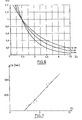
- FIG. 6 illustrates in particular the function connecting the energy W2 to the acoustic impedance of the cement Zc placed behind the casing, and this as a function of the thickness of the casing (6, 9 and 12 mm).
- FIG. 7 establishes the relationship between the acoustic impedance Zc and the compressive strength of the cement CS which in the present case is equal to QCi.
- FIG. 5 diagrammatically shows the flowchart of the correction or normalization processing carried out by the computer 27.
- the signals Si are directed to the computer 27 in which the processing is first of all initialized by the step 61.
- Each signal Si (with 0 ⁇ i ⁇ 10) is readjusted in depth (block 62), then rectified (block 63).
- the rectified signal is integrated (blocks 64 and 65) during two time windows to produce the signals W2 i and Wl i respectively . From the signals obtained, the ratio W2 i / W1 i is established (block 66).
- the value W1 9 / W2 9 is placed in a buffer memory (block 67) which is updated at each cycle, so as to form for each index i ⁇ 9 the ratio W2 i .W1 9 / W1 i .W2 9 (block 68).
- the value QC i is calculated (block 69) according to the function h of equation (III).
- the QC values are then directed to the magnetic (30) and optical (31) recording systems, while the index i is incremented (block 70) so as to cover a complete cycle. Once the complete cycle is finished, the treatment is initialized again.
- a variant of the embodiment described above and in which the processing is carried out in the surface computer consists in processing part of the signal Si or all of the signal Si in a microprocessor provided for this purpose and located in the cartridge electronic 19. It is also possible, by recording the Si signals, to carry out further processing in a computer center.
- the correction method according to the invention therefore makes it possible, in this application, to eliminate the factor due to the attenuation undergone through the propagation medium and, consequently, to evaluate the roughness of the inner wall of the casing and its degree of corrosion, regardless of the frequency range of the acoustic pulse.
- Another application of the invention consists in correcting in situ the function connecting the thickness of the casing and its resonant frequency. This function has been described in French patent application No. 78 20515 mentioned above.
- the correction method of the invention makes it possible to correct the relationship existing between the thickness of the reference reflector 24 which is very precisely known and its resonant frequency which is extracted from the signal S9. This corrected relationship therefore makes it possible to determine, with great precision, the real thickness of the casing with regard to each radial transducer Ti as a function of the resonance frequency of the corresponding signal Si.
- correction and / or normalization process described in the context of the present invention can also be used to verify and / or advantageously replace another normalization technique, in particular that of the linear type which was described in French patent application No 84.13220 filed August 24, 1984 in the name of the plaintiff.
Landscapes
- Life Sciences & Earth Sciences (AREA)
- Engineering & Computer Science (AREA)
- Physics & Mathematics (AREA)
- Geology (AREA)
- Mining & Mineral Resources (AREA)
- General Life Sciences & Earth Sciences (AREA)
- Environmental & Geological Engineering (AREA)
- Geophysics (AREA)
- Acoustics & Sound (AREA)
- Quality & Reliability (AREA)
- Geochemistry & Mineralogy (AREA)
- Fluid Mechanics (AREA)
- Remote Sensing (AREA)
- General Physics & Mathematics (AREA)
- Investigating Or Analyzing Materials By The Use Of Ultrasonic Waves (AREA)
- Geophysics And Detection Of Objects (AREA)
- Investigating Or Analyzing Materials By The Use Of Magnetic Means (AREA)
- Length Measuring Devices Characterised By Use Of Acoustic Means (AREA)
Priority Applications (1)
| Application Number | Priority Date | Filing Date | Title |
|---|---|---|---|
| AT85401716T ATE43184T1 (de) | 1984-09-05 | 1985-09-05 | Verfahren und messgeraet zur akustischen kontrolle eines mit einem rohr ausgeruesteten bohrlochs. |
Applications Claiming Priority (2)
| Application Number | Priority Date | Filing Date | Title |
|---|---|---|---|
| FR8413673A FR2569859B1 (fr) | 1984-09-05 | 1984-09-05 | Procede et dispositif de diagraphie pour l'inspection acoustique d'un sondage muni d'un tubage |
| FR8413673 | 1984-09-05 |
Publications (2)
| Publication Number | Publication Date |
|---|---|
| EP0176408A1 true EP0176408A1 (de) | 1986-04-02 |
| EP0176408B1 EP0176408B1 (de) | 1989-05-17 |
Family
ID=9307460
Family Applications (1)
| Application Number | Title | Priority Date | Filing Date |
|---|---|---|---|
| EP85401716A Expired EP0176408B1 (de) | 1984-09-05 | 1985-09-05 | Verfahren und Messgerät zur akustischen Kontrolle eines mit einem Rohr ausgerüsteten Bohrlochs |
Country Status (5)
| Country | Link |
|---|---|
| US (1) | US4685092A (de) |
| EP (1) | EP0176408B1 (de) |
| AT (1) | ATE43184T1 (de) |
| DE (1) | DE3570293D1 (de) |
| FR (1) | FR2569859B1 (de) |
Cited By (2)
| Publication number | Priority date | Publication date | Assignee | Title |
|---|---|---|---|---|
| EP0388315A1 (de) * | 1989-03-17 | 1990-09-19 | Societe De Prospection Electrique Schlumberger | Verfahren und Vorrichtung zum Aufzeichnen von Bohrlochmessungen mit einem Sensor, der die Bohrlochwand entlang des Umfangs abtastet, insbesondere um diesen Sensor zu kalibrieren |
| FR2646513A1 (fr) * | 1989-04-26 | 1990-11-02 | Schlumberger Prospection | Procede et dispositif de diagraphie pour l'inspection acoustique d'un sondage muni d'un tubage |
Families Citing this family (40)
| Publication number | Priority date | Publication date | Assignee | Title |
|---|---|---|---|---|
| US4744030A (en) * | 1986-04-29 | 1988-05-10 | Western Atlas International, Inc. | Method and apparatus for measuring internal casing wear |
| US4809237A (en) * | 1987-10-01 | 1989-02-28 | Western Atlas International, Inc. | Method for monitoring the goodness of the cement bond to a borehole casing |
| US5072388A (en) * | 1990-01-31 | 1991-12-10 | Union Oil Company Of California | Lined casing inspection method |
| US5138585A (en) * | 1990-04-27 | 1992-08-11 | Chevron Research & Technology Company | Method for fluid identification and evaluation within wellbores using ultrasonic scanning |
| FR2691747A1 (fr) * | 1992-06-02 | 1993-12-03 | Chevron Res & Tech | Procédé d'utilisation de données provenant d'un télécapteur de trou de sonde dans un puits actif pour déterminer des propriétés de fluides. |
| US6070832A (en) * | 1994-02-08 | 2000-06-06 | The United States Of America As Represented By The Secretary Of The Air Force | Ultrasonic angular measurement system |
| US5491668A (en) * | 1994-05-13 | 1996-02-13 | Western Atlas International, Inc. | Method for determining the thickness of a casing in a wellbore by signal processing pulse-echo data from an acoustic pulse-echo imaging tool |
| US5525797A (en) * | 1994-10-21 | 1996-06-11 | Gas Research Institute | Formation density tool for use in cased and open holes |
| US5627368A (en) * | 1995-07-05 | 1997-05-06 | Gas Research Institute | Four-detector formation-density tool for use in cased and open holes |
| GB9621236D0 (en) * | 1996-10-11 | 1996-11-27 | Schlumberger Ltd | Apparatus and method for borehole seismic exploration |
| US5996711A (en) * | 1997-04-14 | 1999-12-07 | Schlumberger Technology Corporation | Method and apparatus for locating indexing systems in a cased well and conducting multilateral branch operations |
| US6002639A (en) * | 1997-05-14 | 1999-12-14 | Gas Research Institute | Sensor configuration for nulling reverberations to image behind reflective layers |
| US6125079A (en) * | 1997-05-14 | 2000-09-26 | Gas Research Institute | System and method for providing dual distance transducers to image behind an acoustically reflective layer |
| US6021093A (en) * | 1997-05-14 | 2000-02-01 | Gas Research Institute | Transducer configuration having a multiple viewing position feature |
| US5995447A (en) * | 1997-05-14 | 1999-11-30 | Gas Research Institute | System and method for processing acoustic signals to image behind reflective layers |
| US6041861A (en) * | 1997-12-17 | 2000-03-28 | Halliburton Energy Services, Inc. | Method to determine self-calibrated circumferential cased bond impedance |
| US6050141A (en) * | 1998-08-28 | 2000-04-18 | Computalog Research, Inc. | Method and apparatus for acoustic logging of fluid density and wet cement plugs in boreholes |
| US7514930B2 (en) * | 2003-12-02 | 2009-04-07 | Schlumberger Technology Corporation | Apparatus and method for addressing borehole eccentricity effects |
| US20060067162A1 (en) * | 2004-09-29 | 2006-03-30 | Blankinship Thomas J | Ultrasonic cement scanner |
| US7296927B2 (en) * | 2005-04-07 | 2007-11-20 | Halliburton Energy Services, Inc. | Laboratory apparatus and method for evaluating cement performance for a wellbore |
| EP1736634A1 (de) * | 2005-06-24 | 2006-12-27 | Services Petroliers Schlumberger | Ein Ultraschallschätzungsverfahren und Vorrichtung für ein verrohrtes Bohrloch |
| US7380466B2 (en) * | 2005-08-18 | 2008-06-03 | Halliburton Energy Services, Inc. | Apparatus and method for determining mechanical properties of cement for a well bore |
| GB0620672D0 (en) * | 2006-10-18 | 2006-11-29 | Specialised Petroleum Serv Ltd | Cement evaluation method and tool |
| US7549320B2 (en) | 2007-01-11 | 2009-06-23 | Halliburton Energy Services, Inc. | Measuring cement properties |
| US7621186B2 (en) * | 2007-01-31 | 2009-11-24 | Halliburton Energy Services, Inc. | Testing mechanical properties |
| US7552648B2 (en) * | 2007-09-28 | 2009-06-30 | Halliburton Energy Services, Inc. | Measuring mechanical properties |
| WO2010040045A2 (en) * | 2008-10-03 | 2010-04-08 | Schlumberger Canada Limited | Identification of casing collars while drilling and post drilling and using lwd and wireline |
| US8601882B2 (en) | 2009-02-20 | 2013-12-10 | Halliburton Energy Sevices, Inc. | In situ testing of mechanical properties of cementitious materials |
| US8783091B2 (en) | 2009-10-28 | 2014-07-22 | Halliburton Energy Services, Inc. | Cement testing |
| US20120145475A1 (en) * | 2010-12-13 | 2012-06-14 | James Graham Dunkelberg | Apparatus and method for generating and propagating polarized acousto-elastic waves |
| US8824240B2 (en) | 2011-09-07 | 2014-09-02 | Weatherford/Lamb, Inc. | Apparatus and method for measuring the acoustic impedance of wellbore fluids |
| US8960013B2 (en) | 2012-03-01 | 2015-02-24 | Halliburton Energy Services, Inc. | Cement testing |
| US8794078B2 (en) | 2012-07-05 | 2014-08-05 | Halliburton Energy Services, Inc. | Cement testing |
| EP2803816B1 (de) * | 2013-05-16 | 2017-03-22 | Services Pétroliers Schlumberger | Systeme und Verfahren für Zementbeurteilung |
| GB2520969A (en) * | 2013-12-05 | 2015-06-10 | Maersk Olie & Gas | Downhole sonar |
| US10358905B2 (en) * | 2014-01-13 | 2019-07-23 | Weatherford Technology Holdings, Llc | Ultrasonic logging methods and apparatus for measuring cement and casing properties using acoustic echoes |
| US10012749B2 (en) * | 2014-10-20 | 2018-07-03 | Schlumberger Technology Corporation | Fast model based inversion of acoustic impedance of annulus behind casing |
| US10174604B2 (en) | 2016-05-24 | 2019-01-08 | Weatherford Technology Holdings, Llc | Ultrasonic cement and casing thickness evaluation |
| JP7743176B2 (ja) * | 2020-11-11 | 2025-09-24 | 株式会社東芝 | 非接触振動計測装置および非接触振動計測方法 |
| GB2603952B (en) * | 2021-02-22 | 2023-05-17 | Cereus Ultrasonics Ltd | Analysing structures within a borehole |
Citations (2)
| Publication number | Priority date | Publication date | Assignee | Title |
|---|---|---|---|---|
| US3175639A (en) * | 1960-10-19 | 1965-03-30 | Liben William | Method for measuring formation porosity, permeability and mud cake thickness in oil well bore holes by sonic pulses |
| EP0089892A2 (de) * | 1982-03-24 | 1983-09-28 | Schlumberger Limited | Verfahren und Gerät zur Untersuchung des Abstandes zwischen Bohrlochmessgerät und Bohrlochwand |
Family Cites Families (4)
| Publication number | Priority date | Publication date | Assignee | Title |
|---|---|---|---|---|
| US4382290A (en) * | 1977-07-11 | 1983-05-03 | Schlumberger Technology Corporation | Apparatus for acoustically investigating a borehole |
| US4255798A (en) * | 1978-05-30 | 1981-03-10 | Schlumberger Technology Corp. | Method and apparatus for acoustically investigating a casing and cement bond in a borehole |
| FR2491123A1 (fr) * | 1980-09-30 | 1982-04-02 | Schlumberger Prospection | Procede et dispositif d'obtention d'un enregistrement de la qualite de cimentation dans un sondage |
| US4571693A (en) * | 1983-03-09 | 1986-02-18 | Nl Industries, Inc. | Acoustic device for measuring fluid properties |
-
1984
- 1984-09-05 FR FR8413673A patent/FR2569859B1/fr not_active Expired
-
1985
- 1985-09-05 AT AT85401716T patent/ATE43184T1/de active
- 1985-09-05 EP EP85401716A patent/EP0176408B1/de not_active Expired
- 1985-09-05 DE DE8585401716T patent/DE3570293D1/de not_active Expired
- 1985-09-05 US US06/772,594 patent/US4685092A/en not_active Expired - Fee Related
Patent Citations (2)
| Publication number | Priority date | Publication date | Assignee | Title |
|---|---|---|---|---|
| US3175639A (en) * | 1960-10-19 | 1965-03-30 | Liben William | Method for measuring formation porosity, permeability and mud cake thickness in oil well bore holes by sonic pulses |
| EP0089892A2 (de) * | 1982-03-24 | 1983-09-28 | Schlumberger Limited | Verfahren und Gerät zur Untersuchung des Abstandes zwischen Bohrlochmessgerät und Bohrlochwand |
Cited By (5)
| Publication number | Priority date | Publication date | Assignee | Title |
|---|---|---|---|---|
| EP0388315A1 (de) * | 1989-03-17 | 1990-09-19 | Societe De Prospection Electrique Schlumberger | Verfahren und Vorrichtung zum Aufzeichnen von Bohrlochmessungen mit einem Sensor, der die Bohrlochwand entlang des Umfangs abtastet, insbesondere um diesen Sensor zu kalibrieren |
| FR2644591A1 (fr) * | 1989-03-17 | 1990-09-21 | Schlumberger Prospection | Procede et dispositif de diagraphie utilisant un capteur effectuant un balayage circonferentiel de la paroi d'un puits de forage, notamment afin d'etalonner ce capteur |
| US4970695A (en) * | 1989-03-17 | 1990-11-13 | Schlumberger Technology Corporation | In situ calibration of a sensor |
| FR2646513A1 (fr) * | 1989-04-26 | 1990-11-02 | Schlumberger Prospection | Procede et dispositif de diagraphie pour l'inspection acoustique d'un sondage muni d'un tubage |
| EP0395499A3 (de) * | 1989-04-26 | 1991-01-23 | Schlumberger Limited | Verfahren und Gerät zur akustischen Untersuchung der in einem Bohrloch zementierten Verrohrung |
Also Published As
| Publication number | Publication date |
|---|---|
| FR2569859A1 (fr) | 1986-03-07 |
| EP0176408B1 (de) | 1989-05-17 |
| FR2569859B1 (fr) | 1986-08-29 |
| US4685092A (en) | 1987-08-04 |
| ATE43184T1 (de) | 1989-06-15 |
| DE3570293D1 (en) | 1989-06-22 |
Similar Documents
| Publication | Publication Date | Title |
|---|---|---|
| EP0176408B1 (de) | Verfahren und Messgerät zur akustischen Kontrolle eines mit einem Rohr ausgerüsteten Bohrlochs | |
| EP0176400B1 (de) | Verfahren zur Qualitätsauswertung des ein Bohrloch umgebenden Zements | |
| FR2646513A1 (fr) | Procede et dispositif de diagraphie pour l'inspection acoustique d'un sondage muni d'un tubage | |
| EP0116244B1 (de) | Verfahren und Vorrichtung zur Untersuchung von Brüchen in Materialoberflächen oder Formationen in Bohrlöchern mit Hilfe von Ultraschallechographie | |
| FR2562152A1 (fr) | Procede et appareil de mesure du pouvoir reflecteur d'un sondage pour diametrage en cours de forage | |
| FR3068479A1 (fr) | Compensation de la reponse angulaire pour vsp dsp | |
| CA2050004C (fr) | Mesure de la repartition des concentrations de constituants d'un systeme en centrifugation par emission/reception de signaux mecaniques | |
| FR2669434A1 (fr) | Method and apparatus for broadband measurement of dielectric properties. | |
| FR3037993A1 (de) | ||
| FR2826401A1 (fr) | Outil de diagraphie acoustique a source quadripolaire | |
| FR2844059A1 (fr) | Procede de diagnostic de gisements de petrole et de gaz | |
| CA2543130C (fr) | Procede et dispositif de caracterisation d'un fluide | |
| FR3077142A1 (fr) | Optimisation d’une longueur de référence à des fins de préservation de signal et traitement d’une longueur de référence à des fins de détection de vibration répartie | |
| FR2609177A1 (fr) | Procede et appareil pour former acoustiquement des images de la paroi d'un trou de sonde | |
| CA1129066A (en) | Method and apparatus for acoustically investigating a casing and casing cement bond in borehole penetrating an earth formation | |
| EP0246148A1 (de) | Verfahren zur seismischen Prospektion mit sehr hoher Auflösung für horizontale Bohrlöcher | |
| EP0053525A1 (de) | Verfahren und Anordnung zur seismischen Exploration unter Anwendung der Methode des vertikalen seismischen Profils | |
| FR3036429A1 (de) | ||
| EP0269482B1 (de) | Verfahren zur Feststellung der Verschiedenartigkeit und/oder zur Bestimmung petrophysikalischer Merkmale von geologischen Schichten in einem zu untersuchenden Medium | |
| FR2799552A1 (fr) | Traitement de mesures de formes d'ondes acoustiques provenant d'outils de diagraphie de sondage en matrice | |
| EP0099816A1 (de) | Verfahren und Vorrichtung für Ultraschall Echographie | |
| FR3027946A1 (fr) | Outil d'inspection d'un environnement souterrain a hautes frequences | |
| EP0055634B1 (de) | Aufzeichnungsverfahren einer physikalischen Charakteristik einer Bohrlochwand | |
| FR2740168A1 (fr) | Procede et dispositif de mesure de caracteristiques geometriques d'un puits, notamment d'un puits d'hydrocarbure | |
| WO1999019750A1 (fr) | Procede de traitement sismique et notamment procede de prospection sismique 3d mettant en oeuvre une migration des donnees sismiques |
Legal Events
| Date | Code | Title | Description |
|---|---|---|---|
| PUAI | Public reference made under article 153(3) epc to a published international application that has entered the european phase |
Free format text: ORIGINAL CODE: 0009012 |
|
| AK | Designated contracting states |
Kind code of ref document: A1 Designated state(s): AT DE FR GB IT NL |
|
| 17P | Request for examination filed |
Effective date: 19861001 |
|
| 17Q | First examination report despatched |
Effective date: 19880629 |
|
| GRAA | (expected) grant |
Free format text: ORIGINAL CODE: 0009210 |
|
| AK | Designated contracting states |
Kind code of ref document: B1 Designated state(s): AT DE FR GB IT NL |
|
| PG25 | Lapsed in a contracting state [announced via postgrant information from national office to epo] |
Ref country code: IT Free format text: LAPSE BECAUSE OF FAILURE TO SUBMIT A TRANSLATION OF THE DESCRIPTION OR TO PAY THE FEE WITHIN THE PRESCRIBED TIME-LIMIT;WARNING: LAPSES OF ITALIAN PATENTS WITH EFFECTIVE DATE BEFORE 2007 MAY HAVE OCCURRED AT ANY TIME BEFORE 2007. THE CORRECT EFFECTIVE DATE MAY BE DIFFERENT FROM THE ONE RECORDED. Effective date: 19890517 Ref country code: AT Effective date: 19890517 Ref country code: NL Effective date: 19890517 |
|
| REF | Corresponds to: |
Ref document number: 43184 Country of ref document: AT Date of ref document: 19890615 Kind code of ref document: T |
|
| REF | Corresponds to: |
Ref document number: 3570293 Country of ref document: DE Date of ref document: 19890622 |
|
| GBT | Gb: translation of ep patent filed (gb section 77(6)(a)/1977) | ||
| NLV1 | Nl: lapsed or annulled due to failure to fulfill the requirements of art. 29p and 29m of the patents act | ||
| PLBE | No opposition filed within time limit |
Free format text: ORIGINAL CODE: 0009261 |
|
| STAA | Information on the status of an ep patent application or granted ep patent |
Free format text: STATUS: NO OPPOSITION FILED WITHIN TIME LIMIT |
|
| 26N | No opposition filed | ||
| PGFP | Annual fee paid to national office [announced via postgrant information from national office to epo] |
Ref country code: DE Payment date: 19921019 Year of fee payment: 8 |
|
| PG25 | Lapsed in a contracting state [announced via postgrant information from national office to epo] |
Ref country code: DE Effective date: 19940601 |
|
| PGFP | Annual fee paid to national office [announced via postgrant information from national office to epo] |
Ref country code: FR Payment date: 19950707 Year of fee payment: 11 |
|
| PG25 | Lapsed in a contracting state [announced via postgrant information from national office to epo] |
Ref country code: FR Effective date: 19960930 |
|
| REG | Reference to a national code |
Ref country code: FR Ref legal event code: ST |
|
| REG | Reference to a national code |
Ref country code: FR Ref legal event code: ST |
|
| PGFP | Annual fee paid to national office [announced via postgrant information from national office to epo] |
Ref country code: GB Payment date: 19980701 Year of fee payment: 14 |
|
| PG25 | Lapsed in a contracting state [announced via postgrant information from national office to epo] |
Ref country code: GB Free format text: LAPSE BECAUSE OF NON-PAYMENT OF DUE FEES Effective date: 19990905 |
|
| GBPC | Gb: european patent ceased through non-payment of renewal fee |
Effective date: 19990905 |