EP0176605A2 - Druckgiessverfahren zur Herstellung von Gussstücken mit einer horizontalen Kaltkammer-Druckgiessmaschine sowie Kaltkammer-Druckgiessmaschine zur Durchführung des Verfahrens - Google Patents
Druckgiessverfahren zur Herstellung von Gussstücken mit einer horizontalen Kaltkammer-Druckgiessmaschine sowie Kaltkammer-Druckgiessmaschine zur Durchführung des Verfahrens Download PDFInfo
- Publication number
- EP0176605A2 EP0176605A2 EP84108607A EP84108607A EP0176605A2 EP 0176605 A2 EP0176605 A2 EP 0176605A2 EP 84108607 A EP84108607 A EP 84108607A EP 84108607 A EP84108607 A EP 84108607A EP 0176605 A2 EP0176605 A2 EP 0176605A2
- Authority
- EP
- European Patent Office
- Prior art keywords
- die casting
- filling chamber
- piston
- metal
- riser pipe
- Prior art date
- Legal status (The legal status is an assumption and is not a legal conclusion. Google has not performed a legal analysis and makes no representation as to the accuracy of the status listed.)
- Granted
Links
- 238000004512 die casting Methods 0.000 title claims abstract description 27
- 238000005266 casting Methods 0.000 title claims abstract description 25
- 238000000034 method Methods 0.000 title claims abstract description 19
- 238000004519 manufacturing process Methods 0.000 title claims description 4
- 239000002184 metal Substances 0.000 claims abstract description 38
- 239000000314 lubricant Substances 0.000 claims description 5
- 230000008569 process Effects 0.000 claims description 5
- 238000009826 distribution Methods 0.000 claims description 4
- 238000010438 heat treatment Methods 0.000 claims description 2
- 230000007704 transition Effects 0.000 claims description 2
- 238000001816 cooling Methods 0.000 description 3
- 230000008901 benefit Effects 0.000 description 2
- 239000000155 melt Substances 0.000 description 2
- 238000010008 shearing Methods 0.000 description 2
- 238000005496 tempering Methods 0.000 description 2
- 230000002411 adverse Effects 0.000 description 1
- 230000008859 change Effects 0.000 description 1
- 239000003795 chemical substances by application Substances 0.000 description 1
- 230000000694 effects Effects 0.000 description 1
- 238000000605 extraction Methods 0.000 description 1
- 230000002349 favourable effect Effects 0.000 description 1
- 238000013101 initial test Methods 0.000 description 1
- 239000000463 material Substances 0.000 description 1
- 230000013011 mating Effects 0.000 description 1
- 230000009467 reduction Effects 0.000 description 1
- 238000007789 sealing Methods 0.000 description 1
- 230000036962 time dependent Effects 0.000 description 1
- XLYOFNOQVPJJNP-UHFFFAOYSA-N water Substances O XLYOFNOQVPJJNP-UHFFFAOYSA-N 0.000 description 1
Images

Classifications
-
- B—PERFORMING OPERATIONS; TRANSPORTING
- B22—CASTING; POWDER METALLURGY
- B22D—CASTING OF METALS; CASTING OF OTHER SUBSTANCES BY THE SAME PROCESSES OR DEVICES
- B22D17/00—Pressure die casting or injection die casting, i.e. casting in which the metal is forced into a mould under high pressure
- B22D17/20—Accessories: Details
- B22D17/2015—Means for forcing the molten metal into the die
- B22D17/2038—Heating, cooling or lubricating the injection unit
-
- B—PERFORMING OPERATIONS; TRANSPORTING
- B22—CASTING; POWDER METALLURGY
- B22D—CASTING OF METALS; CASTING OF OTHER SUBSTANCES BY THE SAME PROCESSES OR DEVICES
- B22D17/00—Pressure die casting or injection die casting, i.e. casting in which the metal is forced into a mould under high pressure
- B22D17/08—Cold chamber machines, i.e. with unheated press chamber into which molten metal is ladled
- B22D17/10—Cold chamber machines, i.e. with unheated press chamber into which molten metal is ladled with horizontal press motion
-
- B—PERFORMING OPERATIONS; TRANSPORTING
- B22—CASTING; POWDER METALLURGY
- B22D—CASTING OF METALS; CASTING OF OTHER SUBSTANCES BY THE SAME PROCESSES OR DEVICES
- B22D17/00—Pressure die casting or injection die casting, i.e. casting in which the metal is forced into a mould under high pressure
- B22D17/14—Machines with evacuated die cavity
-
- B—PERFORMING OPERATIONS; TRANSPORTING
- B22—CASTING; POWDER METALLURGY
- B22D—CASTING OF METALS; CASTING OF OTHER SUBSTANCES BY THE SAME PROCESSES OR DEVICES
- B22D17/00—Pressure die casting or injection die casting, i.e. casting in which the metal is forced into a mould under high pressure
- B22D17/20—Accessories: Details
- B22D17/30—Accessories for supplying molten metal, e.g. in rations
Definitions
- the invention relates to a die casting process for the production of castings with a horizontal cold chamber die casting machine, in which the metering of the metal takes place by means of vacuum via a riser pipe and a suction opening into the filling chamber, and when the cooled casting piston is moved forward via the suction opening, metal flakes are sheared off metal stream supplied to the filling chamber; it also relates to a horizontal cold chamber die casting machine for carrying out this method, which has a casting piston and a filling chamber, into which the metal can be introduced from a casting furnace by means of vacuum via a riser pipe.
- the invention has for its object to improve a die casting process of the type mentioned in such a way that the disadvantages mentioned are eliminated and wear damage that occurs is largely avoided, and to find a particularly advantageous device for carrying out such a die casting process.
- this object is achieved in a method of the type mentioned at the outset in that the casting piston runs over the metal flakes as it runs back and only ejects them forward from the filling chamber with at least one additional piston stroke.
- the casting piston is charged with lubricant before the additional piston stroke is carried out: this has the advantage that lubricant can be distributed evenly on the inner surface of the filling chamber during the idle stroke.
- One to three additional piston strokes are advantageously used to eject the metal flakes.
- a further advantageous embodiment of the method according to the invention also consists in the fact that the filling chamber is thermally insulated against heating in the region of the mouth of the riser pipe, whereby it can be prevented that the inside width of the filling chamber varies over its length.
- a significantly favorable influence in the same direction can also be achieved in a fiction
- This method can be achieved with advantage if the filling chamber (instead or additionally) is cooled in the region of the mouth of the riser pipe in such a way that the temperature distribution is essentially constant over the length of the filling chamber.
- Such an embodiment can be made possible, for example, by a conventional heat exchanger.
- the cold chamber die casting machine according to the invention is based on a die casting machine of the type mentioned at the outset and is characterized in that the casting piston is provided on its piston rear side with a beveled end edge and on its front side with an ejection edge for the metal tinsel.
- the die casting machine according to the invention thus works with one on its rear, i.e. Pistons designed to be tapered towards the piston rod, the bevel being designed so that the metal residues (metal flakes) adhering in the filling chamber space can be run over when the piston runs back. Since the pouring plunger is cooled, it cools down even after the pouring residue has been pushed off as a result of the continuously active cooling, such as water cooling.
- the filling chamber has an inner tube and an outer tube, in between area between the two pipes (transition area) a double-start spiral groove is provided, through which a tempering agent can be passed.
- the inner tube is preferably designed as an exchangeable wear part.
- Another preferred embodiment also consists in the fact that in a die casting machine according to the invention, the ratio between the volume of the melt enclosed within the immersed part of the riser pipe to the internal volume of the section of the riser pipe above it (without taking into account the inlet throttle arranged when the riser pipe is run in) is at least 1: 4 .
- the metal level in the casting furnace drops during ongoing production and the associated metal extraction.
- the molten metal is normally metered into the filling chamber by a time-dependent control. This means that readjustments have to be carried out continuously if the same dosing quantities are required.
- the minimum ratio required according to the invention enables high dosing accuracy. If the bath level falls, e.g.
- the necessary dosing time which is due to the fact that the predosed amount of metal in the riser pipe was reduced due to the metal level.
- the effect of a non-uniform pre-metering depending on the metal level is minimized by the intake manifold geometry that is preferably specified in the invention.
- a filling chamber 1 is provided, which is held with a machine plate 2 and is provided with a heat exchanger 4 in the region of the attachment of the riser pipe 3 (opening of the same in the filling chamber 1).
- the riser pipe 3 is flanged to the filling chamber 1 by means of the riser pipe holder 5 and a pressure screw 6.
- the filling chamber 1 carries on one side a fixed mold half 7 and on its other side a closing piece 8, in which a sealing ring 9 is held over a closing ring 10.
- the casting piston 11 Inside the filling chamber 1 is the casting piston 11, which is shown in its starting position. It has a sharp ejection edge 12 at its front end and a sliding edge 13 which is tapered towards the piston rod at its rear end. In this respect, reference is expressly made to the drawing in FIG. 1.
- the riser pipe 3 dips into the molten metal 14 of a casting furnace 15 and has two sections of different internal width, as is clearly shown in the figure.
- the lower part of the inner volume of the suction pipe 17 dips into the metal bath 14. Above it is a larger internal volume 18 of the riser tube 3. If the metal bath level moves from about 16a to 16b (cf. FIG. 1), there is a reduction in the amount of metal pre-metered in area 17. However, this change is negligibly small, since that Volume in the range 17 is very small compared to the volume in area 18.
- a throttle 19 is provided for the entry of the molten metal into the riser pipe 3. The volume of this throttle 19, however, has virtually no influence on the fluctuation in the metered quantity.
- a filling chamber 20 is shown, which is divided longitudinally and consists of an outer jacket part 21, into which grooves 22 are incorporated in the form of a spiral groove, and an inner tube 23: the inner tube 23, which can be regarded as a wearing part consist of the same material as the outer tube 21.
- Both tubes have a bore 24 arranged radially to the longitudinal axis of the tube for the supply of lubricant.
- a metering opening 25 with mating surfaces for receiving the riser pipe 3 is arranged opposite the lubricant bore 24.
- the helical groove 22 is designed in such a way that the temperature control medium can flow back and forth via an outlet 26 and an inlet 27.
- the spiral groove 22 is a double-start spiral groove with a flow, as shown by the arrows in the lower region of the illustration according to FIG. 2 within the grooves.
- the temperature control medium supplied to the double-start spiral groove has an inlet temperature of 200 to 300 ° C and enables a uniform temperature distribution along the filling chamber 20.
- the filling chamber 20 is thus well cooled by a double-start spiral groove 22, as a result of which a very uniform temperature distribution in the filling chamber 20 can be achieved .
- this prevents the filling chamber 20 from expanding too much, for example in the area of the suction pipe 3, the temperature medium being guided between the inner and outer pipes in the double-start spiral groove 22, which ends in a common annular groove.
Landscapes
- Engineering & Computer Science (AREA)
- Mechanical Engineering (AREA)
- Molds, Cores, And Manufacturing Methods Thereof (AREA)
- Injection Moulding Of Plastics Or The Like (AREA)
- Secondary Cells (AREA)
- Battery Electrode And Active Subsutance (AREA)
- Casting Or Compression Moulding Of Plastics Or The Like (AREA)
- Organic Low-Molecular-Weight Compounds And Preparation Thereof (AREA)
- Solid-Sorbent Or Filter-Aiding Compositions (AREA)
- Pharmaceuticals Containing Other Organic And Inorganic Compounds (AREA)
Abstract
Description
- Die Erfindung bezieht sich auf ein Druckgießverfahren zur Herstellung von Gußstücken mit einer horizontalen Kaltkammer-Druckgießmaschine, bei dem die Dosierung des Metalles mittels Vakuum über ein Steigrohr und eine Ansaugöffnung in die Füllkammer hinein erfolgt und beim Vorfahren des gekühlten Gießkolbens über die Ansaugöffnung Metallflitter beim Abscheren des der Füllkammer zugeführten Metallstromes entstehen; sie bezieht sich weiterhin auf eine horizontale Kaltkammer-Druckgießmaschine zur Durchführung dieses Verfahrens, die einen Gießkolben aufweist sowie eine Füllkammer, in die über ein Steigrohr das Metall aus einem Gießofen mittels Vakuum einführbar ist.
- Es ist schon des längeren bekannt, bei einer horizontalen Kaltkammer-Druckgießmaschine die Schmelze über ein Saugrohr mittels Vakuum anzusaugen. Bei Durchführung der bekannten Verfahren ergibt sich jedoch der systembedingte Nachteil, daß beim Vorfahren des Kolbens über die Ansaugöffnung das der Füllkammer zugeführte Metall abgeschert wird und hierdurch Metallflitter zwischen Gießkolben und Füllkammer gebildet werden, die sich bei normalem Arbeitszyklus nicht vollständig entfernen lassen. Diese Metallflitter beeinträchtigen die wirtschaftliche Durchführung des Verfahrens, da sie die Ursache von Kolbenklemmern sowie von erhöhtem Verschleiß an Kol-Aus der US-A-3 009 218 ist es bekannt, Metallflitter dadurch zu entfernen, daß sie durch eine am Abschlußstück befindliche scharfe Kante vom Kolben abgeschert und innerhalb einer ebenfalls am Abschlußstück befindlichen Kammer aufgefangen werden. Das Abscheren des Flitters verursacht jedoch einen erheblichen Kolbenverschleiß, der wirtschaftlich nicht tragbar ist.
- Ausgehend hiervon liegt der Erfindung die Aufgabe zugrunde, ein Druckgießverfahren der eingangs genannten Art dahingehend zu verbessern, daß die erwähnten Nachteile ausgeschaltet und auftretende Verschleißschäden weitestgehend vermieden werden, sowie eine besonders vorteilhafte Vorrichtung zur Durchführung eines solchen Druckgießverfahrens zu finden.
- Erfindungsgemäß wird diese Aufgabe bei einem Verfahren der eingangs genannten Art dadurch gelöst, daß der Gießkolben die Metallflitter beim Zurücklaufen überfährt und sie erst bei mindestens einem weiteren zusätzlichen Kolbenhub nach vorne aus der Füllkammer ausstößt. Vorteilhafterweise wird der Gießkolben dabei vor Ausführung des zusätzlichen Kolbenhubes mit Schmiermittel beaufschlagt: dies bringt den Vorteil, daß beim Leerhub Schmiermittel gleichmäßig an der Innenfläche der Füllkammer verteilt werden kann. Mit Vorteil werden ein bis drei zusätzliche Kolbenhübe zum Ausstoßen der Metallflitter eingesetzt.
- Eine weitere vorteilhafte Ausgestaltung des erfindungsgemäßen Verfahrens besteht auch darin, daß die Füllkammer im Bereich der Einmündung des Steigrohres gegen Erwärmung thermisch isoliert ist, wodurch verhindert werden kann, daß die lichte Weite der Füllkammer über ihre Länge variiert. Ein deutlich günstiger Einfluß in dieselbe Richtung kann auch dadurch bei einem erfindungsgemäßen Verfahren mit Vorteil erreicht werden, wenn die Füllkammer (stattdessen oder zusätzlich) im Bereich der Einmündung des Steigrohres derart gekühlt wird, daß die Temperaturverteilung über die Länge der Füllkammer im wesentlichen konstant ist. Eine solche Ausgestaltung läßt sich z.B. durch einen Wärmetauscher üblicher Bauart ermöglichen.
- Die erfindungsgemäße Kaltkammer-Druckgießmaschine geht aus von einer Druckgießmaschine der eingangs genannten Art und ist dadurch gekennzeichnet, daß der Gießkolben auf seiner Kolbenrückseite mit einer abgeschrägten Endkante sowie auf seiner Vorderseite mit einer Auswurfkante für den Metallflitter versehen ist. Die erfindungsgemäße Druckgießmaschine arbeitet somit mit einem auf seiner Rückseite, d.h. zur Kolbenstange hin abgeschrägt ausgeführten Kolben, wobei die Abschrägung so ausgebildet ist, daß die im Füllkammerraum haftenden Metallreste (Metallflitter) beim Zurücklaufen des Kolbens überfahren werden können. Da der Gießkolben gekühlt ist, kühlt es sich auch nach dem Abstoßen des Gießrestes infolgen der ständig weiterwirkenden Kühlung, etwa einer Wasserkühlung, ab. Hierdurch erhält er beim Zurückfahren in seine Ausgangsposition einen etwas geringeren Durchmesser, was das Überfahren der in der Füllkammer liegenden Metallflitter zusätzlich erleichtert. Die Stirnfläche des Gießkolbens ist jedoch so scharfkantig ausgebildet, daß sie eine scharfe Auswurfkante darstellt. Beim anschließenden erneuten Vorlaufen des Gießkolbens werden durch sei daher die Metallflitter mitgenommen und können am vorderen Ende aus der Kühlkammer ausgestoßen werden.
- In vorteilhafter Ausgestaltung der erfindungsgemäßen Druchgießmaschine ist vorgesehen, daß die Füllkammer ein Innenrohr und ein Außenrohr aufweist, wobei im Zwischenbereich zwischen beiden Rohren (Ubergangsbereich) eine doppelgängige Wendelnute vorgesehen ist, durch welche ein Temperiermittel geleitet werden kann. Vorzugsweise ist das Innenrohr als ein auswechselbares Verschleißteil ausgebildet.
- Eine weitere vorzugsweise Ausgestaltung besteht auch darin, daß bei einer erfindungsgemäßen Druckgießmaschine das Verhältnis zwischen dem innerhalb des eingetauchten Teiles des Steigrohres eingeschlossenen Volumen der Schmelze zum Innenvolumen des darüberliegenden Abschnitts des Steigrohres (ohne Berücksichtigung der beim Einlauf des Steigrohres angeordneten Einlaufdrossel) mindestens 1:4 beträgt. Bei laufender Produktion und damit verbundener Metallentnahme sinkt der Metallspiegel im Gießofen. Normalerweise erfolgt die Dosierung der Metallschmelze in die Füllkammer durch eine zeitabhängige Steuerung. Dies beduetet, daß ständig nachgeregelt werden muß, wenn gleiche Dosiermengen erforderlich sind. Das erfindungsgemäß geforderte Mindestverhältnis ermöglicht eine hohe Dosiergenauigkeit. Bei fallendem Badspiegel verlängert sich z.B. die notwendige Dosierzeit, was daran liegt, daß die durch den Metallstand bedingte vordosierte Metallmenge im Steigrohr verringert wurde. Der Effekt einer ungleichmäßigen Vordosierung je nach Metallstand wird durch die bei der Erfindung vorzugsweise angegebene Saugrohr-Geometrie minimiert.
- Die Erfindung wird nachfolgend anhand der Zeichnung im Prinzip beispielshalber noch näher erläutert. Es zeigen:
- Fig. 1 einen Längsschnitt durch ein Gieß-und Dosiersystem für eine erfindungsgemäße Vakuum-Druckgießmaschine zur Ausführung des erfindungsgemäßen Verfahrens, und
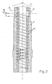
- Fig. 2 einen Längsschnitt durch eine längsgeteilte, temperierfähige Füllkammer zum Einsatz bei einer erfindungsgemäßen Druckgießmaschine.
- Bei der in Fig. 1 gezeigten Druckgießmaschine ist eine Füllkammer 1 vorgesehen, die mit einem Maschinenschild 2 gehalten und im Bereich der Befestigung des Steigrohres 3 (Einmündung desselben in die Füllkammer 1) mit einem Wärmetauscher 4 versehen ist. Das Steigrohr 3 wird mittels Steigrohrhalter 5 über eine Druckschraube 6 an der Füllkammer 1 angeflanscht.
- Die Füllkammer 1 trägt auf ihrer einen Seite eine feste Formhälfte 7 und auf ihrer anderen Seite ein Abschlußstück 8, in dem ein Dichtungsring 9 über einen Abschlußring 10 gehalten wird.
- Im Inneren der Füllkammer 1 befindet sich der Gießkolben 11, der in seiner Startposition eingezeichnet ist. Er weist an seinem vorderen Ende eine scharfe Auswurfkante 12 und an seinem hinteren Ende eine zur Kolbenstange hin abgeschrägt ausgeführte Gleitkante 13 auf. Auf die zeichnerische Darstellung in Fig. 1 wird insoweit ausdrücklich verwiesen.
- Das Steigrohr 3 taucht in die Metallschmelze 14 eines Gießofens 15 ein und weist zwei Abschnitte unterschiedlicher lichter Weite auf, wie dies in der Figur anschaulich gezeigt ist. Der untere Teil des Innenvolumens des Saugrohres 17 taucht in das Metallbad 14 ein. Darüber befindet sich ein größeres Innenvolumen 18 des Steigrohres 3. Wenn sich der Metallbadspiegel etwa von 16a nach 16b (vgl. Fig. 1) bewegt, kommt es zu einer Verringerung der vordosierten Metallmenge im Bereich 17. Diese Veränderung ist aber vernachlässigbar klein, da das Volumen im Bereich 17 im Vergleich zum Volumen im Bereich 18 sehr klein ist. Untem am Steigrohr 3 ist eine Drossel 19 für den Einlauf der Metallschmelze in das Steigrohr 3 vorgesehen. Das Volumen dieser Drossel 19 hat jedoch auf die Schwankung der Dosiermenge so gut wie keinen Einfluß.
- In Fig. 2 ist eine Füllkammer 20 dargestellt, die längsgeteilt ist und aus einem äußeren Mantelteil 21, in das Nuten 22 in Form einer Wendelnut eingearbeitet sind, sowie aus einem Innenrohr 23 besteht: das Innenrohr 23, das als Verschleißteil angesehen werden kann, kann aus dem gleichen Material wie das Außenrohr 21 bestehen. Beide Rohre weisen eine radial zur Rohrlängsachse angeordnete Bohrung 24 zur Zufuhr von Schmiermittel auf. Der Schmiermittelbohrung 24 gegenüber ist eine Dosieröffnung 25 mit Passungsflächen zur Aufnahme des Steigrohres 3 angeordnet. Die Wendelnute 22 ist dergestalt ausgeführt, daß ein Hin- und Rücklauf des Temperiermediums über einen Auslauf 26 sowie einen Einlauf 27 möglich ist. Es handelt sich bei der Wendelnute 22 um eine doppelgängige Wendelnut mit einem Durchfluß, wie ihn die Pfeile im unteren Bereich der Darstellung nach Fig. 2 innerhalb der Nuten zeigen.
- Das der doppelgängigen Wendelnute zugeführte Temperiermedium besitzt eine Einlauftemperatur von 200 bis 300°C und ermöglicht eine gleichmäßige Temperaturverteilung entlang der Füllkammer 20. Die Füllkammer 20 ist somit durch eine doppelgängige Wendelnute 22 gut gekühlt, wodurch sich eine sehr gleichmäßige Temperaturverteilung in der Füllkammer 20 erzielen läßt. Insbesondere wird damit verhindert, daß die Füllkammer 20 sich etwa im Bereich des Saugrohres 3 zu stark ausdehnt, wobei die Führung des Temperaturmediums zwischen Innen- und Außenrohr in der doppelgängigen Wendelnute 22 erfolgt, die am Ende in eine gemeinsame Ringnut ausläuft.
- Erste Versuche mit der erfindungsgemäßen Vorrichtung haben gezeigt, daß mit einer solchermaßen gekühlten Füllkammer 20 nur noch geringe Metallflitter entstehen und dadurch eine besonders gute Lösung der erfindungsgemäßen Aufgabe erfolgen kann.
Claims (9)
Priority Applications (1)
| Application Number | Priority Date | Filing Date | Title |
|---|---|---|---|
| AT84108607T ATE27418T1 (de) | 1984-01-19 | 1984-07-20 | Druckgiessverfahren zur herstellung von gussstuecken mit einer horizontalen kaltkammerdruckgiessmaschine sowie kaltkammerdruckgiessmaschine zur durchfuehrung des verfahrens. |
Applications Claiming Priority (2)
| Application Number | Priority Date | Filing Date | Title |
|---|---|---|---|
| DE3401715 | 1984-01-19 | ||
| DE3401715A DE3401715C2 (de) | 1984-01-19 | 1984-01-19 | Druckgiessverfahren zur Herstellung gasarmer, porenarmer und oxydarmer Gußstücke |
Publications (3)
| Publication Number | Publication Date |
|---|---|
| EP0176605A2 true EP0176605A2 (de) | 1986-04-09 |
| EP0176605A3 EP0176605A3 (en) | 1986-04-30 |
| EP0176605B1 EP0176605B1 (de) | 1987-05-27 |
Family
ID=6225337
Family Applications (1)
| Application Number | Title | Priority Date | Filing Date |
|---|---|---|---|
| EP84108607A Expired EP0176605B1 (de) | 1984-01-19 | 1984-07-20 | Druckgiessverfahren zur Herstellung von Gussstücken mit einer horizontalen Kaltkammer-Druckgiessmaschine sowie Kaltkammer-Druckgiessmaschine zur Durchführung des Verfahrens |
Country Status (6)
| Country | Link |
|---|---|
| US (1) | US4660614A (de) |
| EP (1) | EP0176605B1 (de) |
| JP (1) | JP2645488B2 (de) |
| AT (1) | ATE27418T1 (de) |
| DE (2) | DE3401715C2 (de) |
| NO (1) | NO161657C (de) |
Cited By (5)
| Publication number | Priority date | Publication date | Assignee | Title |
|---|---|---|---|---|
| EP0285686A1 (de) * | 1987-04-07 | 1988-10-12 | Maschinenfabrik Müller-Weingarten AG | Saugrohr für Vakuum-Druckgiessmaschine |
| CN103127714A (zh) * | 2011-11-30 | 2013-06-05 | 京乐产业株式会社 | 游戏机 |
| CN104259429A (zh) * | 2014-09-16 | 2015-01-07 | 苏州橙石铸造有限公司 | 一种卧式冷室压铸机给料系统 |
| CN104259428A (zh) * | 2014-09-16 | 2015-01-07 | 苏州橙石铸造有限公司 | 一种用于压铸机射料装置的加热系统 |
| CN104259423A (zh) * | 2014-09-16 | 2015-01-07 | 苏州橙石铸造有限公司 | 一种用于压铸机上的射料装置 |
Families Citing this family (8)
| Publication number | Priority date | Publication date | Assignee | Title |
|---|---|---|---|---|
| US5076344A (en) * | 1989-03-07 | 1991-12-31 | Aluminum Company Of America | Die-casting process and equipment |
| DE4101592A1 (de) * | 1991-01-21 | 1992-07-23 | Mueller Weingarten Maschf | Druckgiessmaschine |
| US5429174A (en) * | 1993-07-15 | 1995-07-04 | Aluminum Company Of America | Vacuum die casting machine having improved siphon tube and associated method |
| DE19921496A1 (de) * | 1999-05-08 | 2000-11-09 | Mueller Weingarten Maschf | Kolbenseitige Absaugabdichtung bei Anwendung des Vakuumdruckgießverfahren |
| DE19923341B4 (de) * | 1999-05-21 | 2005-03-03 | Audi Ag | Verfahren zum Betreiben einer Druckgießmaschine sowie Druckgießmaschine zur Durchführung des Verfahrens |
| US8714914B2 (en) * | 2009-09-08 | 2014-05-06 | Paul V. Cooper | Molten metal pump filter |
| EP2969311A4 (de) * | 2013-03-12 | 2016-09-14 | United Technologies Corp | Isothermische schussrohranordnung |
| US9205491B2 (en) * | 2014-01-21 | 2015-12-08 | GM Global Technology Operations LLC | Metal pouring method for the die casting process |
Family Cites Families (8)
| Publication number | Priority date | Publication date | Assignee | Title |
|---|---|---|---|---|
| US3009218A (en) * | 1958-10-22 | 1961-11-21 | David M Morgenstern | Apparatus for vacuum feeding a die casting machine |
| US3516480A (en) * | 1968-06-17 | 1970-06-23 | Hamilton Die Cast Inc | Shot tube for a die casting type machine |
| DE1959033B2 (de) * | 1969-11-25 | 1971-05-27 | Siemens Ag | Druckgiessanlage |
| DE2246686C3 (de) * | 1972-09-22 | 1978-03-09 | Maschinenfabrik Weingarten Ag, 7987 Weingarten | Druckgießform für Druckgießmaschinen |
| DE2539280A1 (de) * | 1975-09-04 | 1977-03-17 | Nippon Light Metal Co | Vorrichtung fuer die zufuhr von geschmolzenem metall zu einer druckgiessmaschine |
| JPS5342013A (en) * | 1976-09-29 | 1978-04-17 | Hitachi Ltd | Tape drive mechanism for tape recorder |
| DE3041340A1 (de) * | 1980-11-03 | 1982-05-13 | Maschinenfabrik Weingarten Ag, 7987 Weingarten | Druckgiessverfahren zur herstellung von gasarmer, porenarmer und oxydarmer gussstuecke sowie druckgiessmaschine zur durchfuehrung des verfahrens |
| DE3102055C2 (de) * | 1981-01-23 | 1984-03-22 | Karl Dipl.-Ing. 7000 Stuttgart Göhring | Waagerechte Kaltkammer-Druckgießmaschine |
-
1984
- 1984-01-19 DE DE3401715A patent/DE3401715C2/de not_active Expired
- 1984-07-06 NO NO842769A patent/NO161657C/no unknown
- 1984-07-20 DE DE8484108607T patent/DE3463905D1/de not_active Expired
- 1984-07-20 EP EP84108607A patent/EP0176605B1/de not_active Expired
- 1984-07-20 AT AT84108607T patent/ATE27418T1/de not_active IP Right Cessation
-
1985
- 1985-01-18 JP JP60005977A patent/JP2645488B2/ja not_active Expired - Lifetime
- 1985-01-22 US US06/693,333 patent/US4660614A/en not_active Expired - Lifetime
Cited By (5)
| Publication number | Priority date | Publication date | Assignee | Title |
|---|---|---|---|---|
| EP0285686A1 (de) * | 1987-04-07 | 1988-10-12 | Maschinenfabrik Müller-Weingarten AG | Saugrohr für Vakuum-Druckgiessmaschine |
| CN103127714A (zh) * | 2011-11-30 | 2013-06-05 | 京乐产业株式会社 | 游戏机 |
| CN104259429A (zh) * | 2014-09-16 | 2015-01-07 | 苏州橙石铸造有限公司 | 一种卧式冷室压铸机给料系统 |
| CN104259428A (zh) * | 2014-09-16 | 2015-01-07 | 苏州橙石铸造有限公司 | 一种用于压铸机射料装置的加热系统 |
| CN104259423A (zh) * | 2014-09-16 | 2015-01-07 | 苏州橙石铸造有限公司 | 一种用于压铸机上的射料装置 |
Also Published As
| Publication number | Publication date |
|---|---|
| DE3401715A1 (de) | 1985-08-08 |
| ATE27418T1 (de) | 1987-06-15 |
| NO161657B (no) | 1989-06-05 |
| EP0176605A3 (en) | 1986-04-30 |
| DE3463905D1 (en) | 1987-07-02 |
| JPS60231563A (ja) | 1985-11-18 |
| NO842769L (no) | 1985-07-22 |
| US4660614A (en) | 1987-04-28 |
| NO161657C (no) | 1989-09-13 |
| EP0176605B1 (de) | 1987-05-27 |
| DE3401715C2 (de) | 1986-02-27 |
| JP2645488B2 (ja) | 1997-08-25 |
Similar Documents
| Publication | Publication Date | Title |
|---|---|---|
| EP0176605B1 (de) | Druckgiessverfahren zur Herstellung von Gussstücken mit einer horizontalen Kaltkammer-Druckgiessmaschine sowie Kaltkammer-Druckgiessmaschine zur Durchführung des Verfahrens | |
| DE4313961C2 (de) | Sprühvorrichtung für eine Druckgußvorrichtung und Verfahren zum Besprühen einer Druckgußvorrichtung mit festem Schmiermittel | |
| WO2000048767A1 (de) | Vorrichtung zur herstellung von halbzeugen und formteilen aus metallischem material | |
| DE7834444U1 (de) | Druckgussmaschine | |
| DE2953474C2 (de) | Druckgießverfahren mit Nachverdichtung | |
| DE10393767T5 (de) | Spritzgießeinheit in einer Kaltkammer-Druckgussmaschine und darin angewandtes Dosierverfahren | |
| DE3727640A1 (de) | Steuerverfahren zum entgasungsdruckgiessen und entgasungsdruckgiessmaschine | |
| DE69911262T2 (de) | Selbstschmierender und -reinigender giesskolben für kaltkammerdruckgiessmaschine | |
| DE2162186A1 (de) | Automatische Ölungsanordnung für eine Spritz gußmaschine | |
| DE69215361T2 (de) | Blasformverfahren, unter druck stehende flüssigkeitseinspritzvorrichtung und auswurfvorrichtung | |
| EP0138802A1 (de) | Horizontalstranggiesskokille | |
| DE1458133A1 (de) | Metall-Stranggussverfahren und Einrichtung zu seiner Durchfuehrung | |
| DE2412424A1 (de) | Verfahren zum stranggiessen eines laenglichen metallgegenstands und vorrichtung zur durchfuehrung des verfahrens | |
| DE69102618T2 (de) | Vorrichtung zum Halbwarmschmieden eines Metallwerkstückes und Verfahren zur Anwendung solcher Vorrichtung. | |
| EP1284168B1 (de) | Verfahren zum Betrieb einer Warmkammer-Druckgiessmaschine und Druckgiessmaschine | |
| DD284175A5 (de) | Verfahren zum kuehlen eines metallischen gegenstandes waehrend des stranggiessens | |
| DE2403215A1 (de) | Verfahren zum walzen nahtloser rohre und anlage zur durchfuehrung dieses verfahrens | |
| EP0045956A2 (de) | Stanzwerkzeug | |
| EP3511090A1 (de) | Kaltkammerdruckgiessverfahren und kaltkammerdruckgiessmaschine | |
| DE19833504C2 (de) | Kunststoffschmelze-Schußkolben | |
| DE3013226C2 (de) | ||
| DE2745242A1 (de) | Verfahren und vorrichtung zum schmiermittelauftrag | |
| DE4243827A1 (de) | Gießgarnitur für eine Druckgießmaschine | |
| DE2611793C2 (de) | Anfahrkopf zum horizontalen Stranggießen und Verfahren zum Anfahren des horizontalen Stranggießens | |
| AT277489B (de) | Verfahren und vorrichtung zum homogenisieren des gefueges beim stranggieszen von metallen |
Legal Events
| Date | Code | Title | Description |
|---|---|---|---|
| PUAI | Public reference made under article 153(3) epc to a published international application that has entered the european phase |
Free format text: ORIGINAL CODE: 0009012 |
|
| PUAL | Search report despatched |
Free format text: ORIGINAL CODE: 0009013 |
|
| 17P | Request for examination filed |
Effective date: 19841217 |
|
| AK | Designated contracting states |
Kind code of ref document: A2 Designated state(s): AT BE CH DE FR GB IT LI LU NL SE |
|
| AK | Designated contracting states |
Kind code of ref document: A3 Designated state(s): AT BE CH DE FR GB IT LI LU NL SE |
|
| 17Q | First examination report despatched |
Effective date: 19861120 |
|
| GRAA | (expected) grant |
Free format text: ORIGINAL CODE: 0009210 |
|
| AK | Designated contracting states |
Kind code of ref document: B1 Designated state(s): AT BE CH DE FR GB IT LI LU NL SE |
|
| REF | Corresponds to: |
Ref document number: 27418 Country of ref document: AT Date of ref document: 19870615 Kind code of ref document: T |
|
| ITF | It: translation for a ep patent filed | ||
| REF | Corresponds to: |
Ref document number: 3463905 Country of ref document: DE Date of ref document: 19870702 |
|
| PG25 | Lapsed in a contracting state [announced via postgrant information from national office to epo] |
Ref country code: LU Free format text: LAPSE BECAUSE OF NON-PAYMENT OF DUE FEES Effective date: 19870731 |
|
| ET | Fr: translation filed | ||
| PLBE | No opposition filed within time limit |
Free format text: ORIGINAL CODE: 0009261 |
|
| STAA | Information on the status of an ep patent application or granted ep patent |
Free format text: STATUS: NO OPPOSITION FILED WITHIN TIME LIMIT |
|
| 26N | No opposition filed | ||
| PGFP | Annual fee paid to national office [announced via postgrant information from national office to epo] |
Ref country code: LU Payment date: 19900613 Year of fee payment: 7 |
|
| NLS | Nl: assignments of ep-patents |
Owner name: VEREINIGTE ALUMINIUM-WERKE AKTIENGESELLSCHAFT TE B |
|
| PGFP | Annual fee paid to national office [announced via postgrant information from national office to epo] |
Ref country code: BE Payment date: 19930519 Year of fee payment: 10 |
|
| PGFP | Annual fee paid to national office [announced via postgrant information from national office to epo] |
Ref country code: SE Payment date: 19930524 Year of fee payment: 10 |
|
| PGFP | Annual fee paid to national office [announced via postgrant information from national office to epo] |
Ref country code: GB Payment date: 19930712 Year of fee payment: 10 |
|
| PGFP | Annual fee paid to national office [announced via postgrant information from national office to epo] |
Ref country code: AT Payment date: 19930730 Year of fee payment: 10 |
|
| ITTA | It: last paid annual fee | ||
| PGFP | Annual fee paid to national office [announced via postgrant information from national office to epo] |
Ref country code: NL Payment date: 19930731 Year of fee payment: 10 |
|
| PG25 | Lapsed in a contracting state [announced via postgrant information from national office to epo] |
Ref country code: GB Effective date: 19940720 Ref country code: AT Effective date: 19940720 |
|
| PG25 | Lapsed in a contracting state [announced via postgrant information from national office to epo] |
Ref country code: SE Effective date: 19940721 |
|
| PG25 | Lapsed in a contracting state [announced via postgrant information from national office to epo] |
Ref country code: BE Effective date: 19940731 |
|
| BERE | Be: lapsed |
Owner name: VEREINIGTE ALUMINIUM-WERKE A.G. Effective date: 19940731 Owner name: MASCHINENFABRIK MULLER-WEINGARTEN A.G. Effective date: 19940731 |
|
| EUG | Se: european patent has lapsed |
Ref document number: 84108607.7 Effective date: 19950210 |
|
| PG25 | Lapsed in a contracting state [announced via postgrant information from national office to epo] |
Ref country code: NL Effective date: 19950201 |
|
| NLV4 | Nl: lapsed or anulled due to non-payment of the annual fee | ||
| GBPC | Gb: european patent ceased through non-payment of renewal fee |
Effective date: 19940720 |
|
| EUG | Se: european patent has lapsed |
Ref document number: 84108607.7 |
|
| PGFP | Annual fee paid to national office [announced via postgrant information from national office to epo] |
Ref country code: CH Payment date: 20000628 Year of fee payment: 17 |
|
| PGFP | Annual fee paid to national office [announced via postgrant information from national office to epo] |
Ref country code: FR Payment date: 20000717 Year of fee payment: 17 |
|
| PG25 | Lapsed in a contracting state [announced via postgrant information from national office to epo] |
Ref country code: LI Free format text: LAPSE BECAUSE OF NON-PAYMENT OF DUE FEES Effective date: 20010731 Ref country code: CH Free format text: LAPSE BECAUSE OF NON-PAYMENT OF DUE FEES Effective date: 20010731 |
|
| REG | Reference to a national code |
Ref country code: CH Ref legal event code: PL |
|
| PG25 | Lapsed in a contracting state [announced via postgrant information from national office to epo] |
Ref country code: FR Free format text: LAPSE BECAUSE OF NON-PAYMENT OF DUE FEES Effective date: 20020329 |
|
| REG | Reference to a national code |
Ref country code: FR Ref legal event code: ST |
|
| PGFP | Annual fee paid to national office [announced via postgrant information from national office to epo] |
Ref country code: DE Payment date: 20020708 Year of fee payment: 19 |
|
| PG25 | Lapsed in a contracting state [announced via postgrant information from national office to epo] |
Ref country code: DE Free format text: LAPSE BECAUSE OF NON-PAYMENT OF DUE FEES Effective date: 20040203 |