EP0176993B1 - Referenzsignalwiedergabegerät - Google Patents
Referenzsignalwiedergabegerät Download PDFInfo
- Publication number
- EP0176993B1 EP0176993B1 EP85112313A EP85112313A EP0176993B1 EP 0176993 B1 EP0176993 B1 EP 0176993B1 EP 85112313 A EP85112313 A EP 85112313A EP 85112313 A EP85112313 A EP 85112313A EP 0176993 B1 EP0176993 B1 EP 0176993B1
- Authority
- EP
- European Patent Office
- Prior art keywords
- phase
- signal
- output
- reference signal
- mode
- Prior art date
- Legal status (The legal status is an assumption and is not a legal conclusion. Google has not performed a legal analysis and makes no representation as to the accuracy of the status listed.)
- Expired - Lifetime
Links
- 230000003111 delayed effect Effects 0.000 claims description 18
- 238000001514 detection method Methods 0.000 claims description 4
- 230000007274 generation of a signal involved in cell-cell signaling Effects 0.000 claims 12
- 238000010586 diagram Methods 0.000 description 3
- 230000001360 synchronised effect Effects 0.000 description 2
- 230000005540 biological transmission Effects 0.000 description 1
- 230000000694 effects Effects 0.000 description 1
- 230000005684 electric field Effects 0.000 description 1
- 230000010354 integration Effects 0.000 description 1
- 238000000034 method Methods 0.000 description 1
- 238000005070 sampling Methods 0.000 description 1
Images




Classifications
-
- H—ELECTRICITY
- H04—ELECTRIC COMMUNICATION TECHNIQUE
- H04N—PICTORIAL COMMUNICATION, e.g. TELEVISION
- H04N7/00—Television systems
- H04N7/08—Systems for the simultaneous or sequential transmission of more than one television signal, e.g. additional information signals, the signals occupying wholly or partially the same frequency band, e.g. by time division
- H04N7/087—Systems for the simultaneous or sequential transmission of more than one television signal, e.g. additional information signals, the signals occupying wholly or partially the same frequency band, e.g. by time division with signal insertion during the vertical blanking interval only
-
- H—ELECTRICITY
- H04—ELECTRIC COMMUNICATION TECHNIQUE
- H04N—PICTORIAL COMMUNICATION, e.g. TELEVISION
- H04N7/00—Television systems
- H04N7/025—Systems for the transmission of digital non-picture data, e.g. of text during the active part of a television frame
- H04N7/035—Circuits for the digital non-picture data signal, e.g. for slicing of the data signal, for regeneration of the data-clock signal, for error detection or correction of the data signal
Definitions
- This invention relates to a reference signal reproduction apparatus for digitally reproducing a reference signal that is synchronous with an arriving reference signal.
- Teletext systems in which digital signals are superposed in the vertical blanking interval of the television signal, and during the horizontal scan period, in which normally no picture signals are sent, have been developed.
- image data such as characters and graphics included in a superposed digital signal (hereinafter referred to as a character transmission signal) is extracted and displayed on the CRT, etc.
- the horizontal synchronizing signal of the television signal is used as the reference for extracting the above character broadcasting signal.
- a digital PLL circuit is known from EP-A-0012899, in which a programmable divider exactly divides the frequency output of a VCO so that the local frequency is pulled by the programmable divider while the local phase is pulled by the VCO.
- the object of this invention is to provide a reference signal reproduction device which can reproduce a stable reference signal in phase with an arriving reference signal.
- the phases of the reproduction reference signal applied as a decode output of a counter and the arriving reference signal are phase-compared, the phase of the reproduced reference signal in relation to the arriving reference signal is discriminated by three modes, i.e delay, advance or in phase based on this phase comparison result, and the counter division ratio is set, based on this discrimination, such that the phase of the reproduction reference signal is pulled into that of the arriving reference signal.
- Fig. 1 is a schematic representation of the structure of one embodiment of this invention.
- a clock CK of 8/5 fsc (fsc: color subcarrier frequency), which is the reference for sampling the received character broadcasting signal, is applied to terminal 10.
- This clock CK is also supplied to counter 20 and is divided by a prescribed ratio (N).
- the count value Q of the division in counter 20 is applied to decoder 30, which decodes the value and generates a reproduction reference signal RS and a reset signal R.
- Reproduction reference signal RS is supplied to signal generator 40 and phase comparator 50.
- Generator 40 generates a reproduction horizontal synchronizing signal H based on reproduction reference signal RS.
- This signal RS is led to terminal 60.
- Phase comparator 50 compares the phases of reproduction reference signal RS and the received horizontal synchronizing signal (arriving reference signal TH) applied to terminal 70 and sends the result of the comparison to phase discriminator 80.
- phase discriminator 80 discriminates whether the phase of the reproduction reference signal RS is in the advanced, delayed or in-phase mode in relation to the received horizontal synchronizing signal TH.
- the result of this discrimination is sent to division setting circuit 90.
- the circuit 90 sets the division ratio of counter 20 such that the reproduction reference signal RS is pulled into the received horizontal synchronizing signal TH by using the reset signal R.
- a result signal RS synchronizing with the arriving horizontal synchronizing signal TH is obtained and, thereby the reproduction horizontal synchronizing signal H that is synchronizing with the signal TH is obtained.
- Signal G which is supplied to phase comparator 50 via terminal 100, is the vertical synchronizing gate signal output during the vertical synchronizing signal period.
- the phase comparator 50 in accordance with signal G outputs the same phase comparison result as in the in-phase mode without comparing phases during the vertical synchronizing signal period and,thereby, dividing ratio Nthat is the same as in the in-phase mode is set in the vertical synchronizing signal period.
- Fig. 2 shows an actual example of the device shown in Fig. 1 and the same reference numerals have been used for the same parts.
- decoder 30 outputs three signals P4, P5, P6 as the reproduction reference signal RS and outputs three signals P1, P2, P3 as the reset signal R.
- Reproduction horizontal synchronizing signal generator 40 is composed of flip-flop circuits and outputs reproduction horizontal synchronizing dignal H based on signals P5 and P6.
- Phase comparator 50 comprises flip-flop circuits 51, 52 which latch the level (polarity) of received horizontal synchronizing signal TH at the edge timing of signals P4 and P5, respectively. Based on the level of signal TH, which is detected in this way, phase discriminator 80 discriminates which mode it is, and dividing ratio setting circuit 90 sets the dividing ratio N of counter 20 accordingly.
- counter 20 divides the clock CK by 364.
- 8/5 fsc and f H (f H : horizontal frequency) have the following relationship, it is possible to obtain the signals P1-P6 in horizontal period by dividingby365.
- Counter 20 counts the 8/5 fsc clock CK (See Fig. 3.) and outputs O0O8. This output is shown in decimal numbers in Fig. 3. Decoder 30 decodes outputs QO-Q8 and outputs signals P1-P6. Reset signals P1-P3 have a mutual phase difference of one cycle of the reference clock CK and can each set the dividing ratio of counter 20 to 363, 364, 365.
- Flip-flop circuits 51, 52 using signals P4, P5 output from decoder 30 as clocks, latch signal TH supplied to terminal 70. Accordingly, the polarity (level) of the received horizontal synchronizing signal TH at the leading edge of signals P4, P5 is detected by flip-flop circuits 51, 52. As shown in Fig. 3, signals P4, P5 are obtained when the count value of counter 20 reaches 319,320, respectively. Accordingly, a change of polarity of signal TH is detected within one clock.
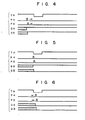
- phase discrimination circuit 80 discriminates the phase of received horizontal synchronizing signal TH in relation to reproduction reference signal RS. For example, in the phase mode shown in Fig. 4, i.e., when signal TH is delayed to signals P4, P5, as outputs QA, QB of the flip-flop circuits 51, 52 are both high level H, a discrimination signal DN indicative of the advanced mode is obtained from AND gate 81. In the phase mode shown in Fig. 4, i.e., when signal TH is delayed to signals P4, P5, as outputs QA, QB of the flip-flop circuits 51, 52 are both high level H, a discrimination signal DN indicative of the advanced mode is obtained from AND gate 81. In the phase mode shown in Fig.
- Dividing ratio setting circuit 90 sets the dividing ratio N of counter 20 based on the three signals DN, UP, HD from phase discriminator 80. Signals P1, P2, P3 are selected by AND gates 92, 93, 91 using signals UP, HD, DN, respectively, and supplied to counter 20 via NOR gate 94 as the reset signal R (Fig. 3). For example, when signal UP is obtained, the signal P1, which is obtained when the count value of counter 20 reaches 362, is selected, inverted by NOR gate 94, and supplied to the reset terminal of counter 20 so counter 20 issreset at the time when the count value reaches 362.
- counter 20 divides the clock CK by 363 so the phases of signals P4, P5 are advanced, pulling signals P4, P5, which have phases that are later than the signal TH, ahead.
- Fig. 3 shows the case where signal P2 is selected as the reset signal R by signal HD.
- the vertical synchronizing gate signal G supplied to terminal 100 is supplied to the preset and reset terminals of flip-flop circuits 51, 52.
- Signal G becomes L during the vertical synchronizing signal period so output QA of flip-flop circuit 51 during this period is "H”, output QB of flip-flop circuit 52 is "L”, and signal HD is output from phase discriminator 80.
- reproduction reference signal RS is not influenced by the cut-off and equalizing pulses in the vertical synchronizing signal period and no variation in the phase occurs.
- the phase mode is discriminated to be either advanced, delayed or in-phase, and in the in-phase mode the dividing ratio is set at 364. Therefore, once the phase is matched as to does not vary, it is possible to obtain a stable reproduction reference signal RS. Accordingly, the signal H obtained from this signal RS is phase synchronu- ous with the signal TH and, therefore it is possible to stably extract the character broadcasting signal.
- FIG. 7 Another embodiment of the invention is described with reference to Fig. 7 in which the same parts as in Fig. 2 have been given the same reference numerals.
- the discrimination signals DN, UP, HD for three modes are digitally integrated, and when this integrated output satisfies a specific condition, the signals become effective (are enabled) for the first time.
- Fig. 7 the difference from Fig. 2 lies in decoder 110 and phase discriminator 120.
- Decoder 110 outputs signal p7 as well as signals P1-P6.
- Phase discriminator 120 comprises first phase discriminator 121 and second phase discriminator 122.
- First phase discriminator 121 is constructed exactly the same as phase discriminator 80 of Fig. 2 and performs the same operation.
- Second phase discriminator 122 digitally integrates the discrimination output of first phase discriminator 121 and, based on the integration result, sends a correct discrimination output to dividing ratio setting circuit 90.
- Counter 2A or 4A first enables signal DN or UP when, for example, the counte value becomes 8, and sends the corresponding signals DN1 or UP1 to dividing ratio setting circuit 90.
- signal HD1 indicating the in-phase mode is obtained from NOR gate 5A to dividing ratio setting circuit 90.
- Reset circuit 6A resets counters 2A and 4A with signal P7 when signals DN1, UP1 are output and when signal HD is output from first phase discriminator 121.
- Fig. 4 shows a case where signals P4, P5 lead signal TH.
- signal DN indicating the advanced mode is output from first phase discriminator 121.
- Second phase discriminator 122 outputs a signal HD1 showing the in-phase mode until signal DN has been repeatedly output eight times. Accordingly, in this case, circuit 90 selects signal P2 and the dividing ratio of counter 20 is set at 364.
- second phase discriminator 122 outputs signal DN1 indicating the advanced mode.
- dividing ratio setting circuit 90 resets counter 20 with signal P3. Accordingly, the dividing ratio N of counter 20 is set at 365 and, thereby, signals P4, P5 are delayed.
- counters 2A, 4A are reset by signals P7 and, thus, second phase discriminator 122 again detects the repetition of signal DN or UP.
- the dividing ratio of counter 20 is again switched from 365 to 364. Then, when signal DN is obtained repeatedly, the above operation is repeated, and finally the signals P4, P5 are synchronized with signals TH, as is shown in Fig. 5.
- Fig. 6 shows the case where reproduction reference signal P4, P5 lag behind signal TH, and, except for the output of signals UP, UP1, this example is the same as in Fig. 4 so a description has been omitted.
- second phase discriminator 122 when the HD signal - indicating the in-phase mode is obtained from first phase discriminator 121, even if signal DN or UP have been output, as long as the number of outputs has not reached eight, second phase discriminator 122 will continue to output signal HD1 so it is possible to maintain a phase-locked state. Accordingly, in this embodiment when many noise components are included in the signal TH as during the presence of a weak electrical field, etc., the phase-locked state is not disturbed even if signals UP or DN are output erroneously from first phase discriminator 121.
- signal HD1 is always output. That is, this embodiment does not detect the repetition of the signal HD. Accordingly, even if the phases of signals P4, P5 and signal TH match, there is no problem with performing the mistaken pulling-in process.
- Phase discriminator 130 includes first and second phase discriminators 131,132 as shown in Fig. 8.
- First phase discriminator 131 is the same as the first phase discriminator described in reference to Fig. 7, whereas, the second phase discriminator 132 also checks the repetition of signal HD as well as that of signals DN, UP.
- signals DN, UP and HD are output from first phase discriminator 131, the gates of corresponding AND gates 1B, 2B, 3B are opened and counters 4B, 5B, 6B count signal P7.
- counter 4B counts signal P7 and when the count of eight is reached the output becomes H.
- counters 6B is 5B count signal P7 and when the count of eight is reached, the output becomes H.
- the outputs of counter 4B or 5B is supplied to set terminal S of flip-flop circuit 8B via NOR gate 7B, and the output of counter 6B is supplied to the reset terminal R of flip-flop circuit 8B.
- Flip-flop circuit 8B is set when the output of counter 4B or 5B becomes H and is reset when the output of counter 6B becomes H.
- selector 10B selects the inputs Al-A3 as the outputs Y1-Y3, and when flip-flop circuit 8b is reset, inputs B1-B3 are selected as the output Y1-Y3. Accordingly, when the repetition of signals DN or UP is detected, signals, DN, UP, HD become descrimination signals DN1, UP1, HD1, respectively, of phase discriminator 130. When, however, the repetition of signal HD is detected, only the input B1 of the three inputs B1-B3 becomes H and the others become L and, therefore, phase discriminator 130 outputs only discrimination signal HD1 indicating the in-phase mode.
- Reference numeral 11B denotes the reset circuit of counters 4B-6B. Any one counter, of the three counters 4B-6B, is reset by the count input of the other two counters via the OR gate b1-b3 corresponding to the counter being reset.
- flip-flop circuit 8B maintains a .set state until the repetition of signal HD is detected. Accordingly, in this embodiment once the repetition of signal DN or UP is detected, the phase pull-in operation continues and, compared with the previous embodiment, the time required until the phase-locked state is reached is reduced.
- either of signals DN, UP or HD may be selected so, similar to the Fig. 7 embodiment, if the phases of signals P4, P5 and signal TH match, it is possible to eliminate the phase pull-in operation.
- signal HD can be selected as signal HD1 and, therefore, while the structure is for detecting the repetition of signal HD, when signals P4, P5 and signal TH match, the phase pulling-in operation can immediately be eliminated.
- the horizontal synchronizing signal H was reproduced, but, the vertical synchronizing signal may be reproduced by changing the dividing ratio.
- This invention may, of course, be applied to a reference signal reproduction apparatus other than in a character broadcasting system.
- phase state is judeged by three modes and a reference signal is reproduced digitally, making the reproduction stable.
Landscapes
- Engineering & Computer Science (AREA)
- Multimedia (AREA)
- Signal Processing (AREA)
- Synchronizing For Television (AREA)
- Stabilization Of Oscillater, Synchronisation, Frequency Synthesizers (AREA)
- Synchronisation In Digital Transmission Systems (AREA)
- Television Signal Processing For Recording (AREA)
Claims (15)
Applications Claiming Priority (4)
| Application Number | Priority Date | Filing Date | Title |
|---|---|---|---|
| JP59201918A JPH0771198B2 (ja) | 1984-09-28 | 1984-09-28 | 基準信号再生回路 |
| JP201918/84 | 1984-09-28 | ||
| JP59201917A JPS6180973A (ja) | 1984-09-28 | 1984-09-28 | 基準信号再生回路 |
| JP201917/84 | 1984-09-28 |
Publications (3)
| Publication Number | Publication Date |
|---|---|
| EP0176993A2 EP0176993A2 (de) | 1986-04-09 |
| EP0176993A3 EP0176993A3 (en) | 1987-05-20 |
| EP0176993B1 true EP0176993B1 (de) | 1990-03-14 |
Family
ID=26513077
Family Applications (1)
| Application Number | Title | Priority Date | Filing Date |
|---|---|---|---|
| EP85112313A Expired - Lifetime EP0176993B1 (de) | 1984-09-28 | 1985-09-27 | Referenzsignalwiedergabegerät |
Country Status (5)
| Country | Link |
|---|---|
| US (1) | US4688094A (de) |
| EP (1) | EP0176993B1 (de) |
| KR (1) | KR890004436B1 (de) |
| CA (1) | CA1227252A (de) |
| DE (1) | DE3576630D1 (de) |
Families Citing this family (10)
| Publication number | Priority date | Publication date | Assignee | Title |
|---|---|---|---|---|
| DE3601858C1 (de) * | 1986-01-23 | 1986-11-27 | Philips Patentverwaltung Gmbh, 2000 Hamburg | Schaltungsanordnung zur Frequenzteilung |
| US4849704A (en) * | 1987-04-15 | 1989-07-18 | Westinghouse Electric Corp. | Duty cycle independent phase detector |
| EP0310088B1 (de) * | 1987-10-01 | 1996-06-05 | Sharp Kabushiki Kaisha | Digitale Phasenregelschleifen-Anordnung |
| US5305106A (en) * | 1989-09-20 | 1994-04-19 | Canon Kabushiki Kaisha | Image signal reproducing apparatus having a synchronizing signal generator |
| JPH04142649A (ja) * | 1990-10-04 | 1992-05-15 | Toshiba Corp | メモリ装置 |
| JP2776098B2 (ja) * | 1991-11-27 | 1998-07-16 | 松下電器産業株式会社 | クロック再生回路および時間軸誤差補正装置 |
| US5418573A (en) * | 1993-07-22 | 1995-05-23 | Philips Electronics North America Corporation | Apparatus and method for producing periodic synchronization references forming a synchronization signal |
| FR2718915B1 (fr) * | 1994-04-19 | 1996-05-15 | Thomson Csf | Procédé et dispositif de calage pour traitement de signaux vidéo à l'émission. |
| US5502751A (en) * | 1994-06-30 | 1996-03-26 | Motorola, Inc. | Digital phase locked loop |
| US5844622A (en) * | 1995-12-12 | 1998-12-01 | Trw Inc. | Digital video horizontal synchronization pulse detector and processor |
Family Cites Families (5)
| Publication number | Priority date | Publication date | Assignee | Title |
|---|---|---|---|---|
| JPS525781B2 (de) * | 1973-06-06 | 1977-02-16 | ||
| US3936762A (en) * | 1974-06-17 | 1976-02-03 | The Charles Stark Draper Laboratory, Inc. | Digital phase-lock loop systems for phase processing of signals |
| US4151485A (en) * | 1977-11-21 | 1979-04-24 | Rockwell International Corporation | Digital clock recovery circuit |
| DE2856211A1 (de) * | 1978-12-27 | 1980-07-03 | Licentia Gmbh | Digitale phasenregelschaltung mit einer hilfsschaltung |
| JPS5686582A (en) * | 1979-12-18 | 1981-07-14 | Fuji Xerox Co Ltd | Quantizing system at reception side for video information transmitter |
-
1985
- 1985-09-27 US US06/781,140 patent/US4688094A/en not_active Expired - Lifetime
- 1985-09-27 EP EP85112313A patent/EP0176993B1/de not_active Expired - Lifetime
- 1985-09-27 CA CA000491735A patent/CA1227252A/en not_active Expired
- 1985-09-27 DE DE8585112313T patent/DE3576630D1/de not_active Expired - Lifetime
- 1985-09-28 KR KR1019850007205A patent/KR890004436B1/ko not_active Expired
Also Published As
| Publication number | Publication date |
|---|---|
| EP0176993A3 (en) | 1987-05-20 |
| KR890004436B1 (ko) | 1989-11-03 |
| US4688094A (en) | 1987-08-18 |
| KR860002930A (ko) | 1986-04-30 |
| EP0176993A2 (de) | 1986-04-09 |
| CA1227252A (en) | 1987-09-22 |
| DE3576630D1 (de) | 1990-04-19 |
Similar Documents
| Publication | Publication Date | Title |
|---|---|---|
| US5453794A (en) | Multistandard video signal decoder | |
| US4600943A (en) | Sampling pulse generator | |
| EP0455957B1 (de) | Detektor für die geraden/ungeraden Treibbilder eines Videosignals | |
| US4821112A (en) | Detection circuit for detecting standard television signals and nonstandard television signals | |
| EP0360510A2 (de) | Videounterscheidung zwischen verschiedenen Videoformaten | |
| US4688094A (en) | Reference signal reproduction apparatus | |
| EP0056649B1 (de) | Empfänger für digitale Signale | |
| US4594516A (en) | Sampling pulse generator | |
| EP0782329B1 (de) | Schaltung zum Erzeugen eines horizontalen Synchronisationssignals und Verfahren dazu | |
| US5309236A (en) | Video signal processing circuit of a broadcasting system | |
| CN1112753A (zh) | 锁相环的鉴相器 | |
| CA1099403A (en) | Vertical synchronizing signal detector for television video signal reception | |
| KR100272734B1 (ko) | 비디오 신호의 큰 위상 시프트에 영향을 받지 않는 수평 라인 카운터 | |
| US5402243A (en) | Regenerating circuit of synchronizing signals for standard video signals | |
| EP0249987B1 (de) | Schaltung zum Erzeugen von Vertikaltreiberimpulsen | |
| GB2229890A (en) | Teletext broadcasting signal generating and receiving apparatus | |
| US7321397B2 (en) | Composite color frame identifier system and method | |
| JPH0231553B2 (de) | ||
| JPS625551B2 (de) | ||
| EP0658296A1 (de) | Vorrichtung zur Erkennung von Fernsehzeilen und Fernsehbildern mit einer hohen Geräuschimmunität | |
| JPH07307727A (ja) | データ信号のサンプリング方法及びその回路 | |
| JP2714221B2 (ja) | テレビジョン方式判別装置 | |
| KR19980016570A (ko) | 수평동기 분리기 | |
| JP3219604B2 (ja) | 標準信号判定装置 | |
| JPH0193266A (ja) | 複合同期信号分離装置 |
Legal Events
| Date | Code | Title | Description |
|---|---|---|---|
| PUAI | Public reference made under article 153(3) epc to a published international application that has entered the european phase |
Free format text: ORIGINAL CODE: 0009012 |
|
| 17P | Request for examination filed |
Effective date: 19850927 |
|
| AK | Designated contracting states |
Kind code of ref document: A2 Designated state(s): DE GB |
|
| PUAL | Search report despatched |
Free format text: ORIGINAL CODE: 0009013 |
|
| AK | Designated contracting states |
Kind code of ref document: A3 Designated state(s): DE GB |
|
| 17Q | First examination report despatched |
Effective date: 19880926 |
|
| GRAA | (expected) grant |
Free format text: ORIGINAL CODE: 0009210 |
|
| AK | Designated contracting states |
Kind code of ref document: B1 Designated state(s): DE GB |
|
| REF | Corresponds to: |
Ref document number: 3576630 Country of ref document: DE Date of ref document: 19900419 |
|
| PLBE | No opposition filed within time limit |
Free format text: ORIGINAL CODE: 0009261 |
|
| STAA | Information on the status of an ep patent application or granted ep patent |
Free format text: STATUS: NO OPPOSITION FILED WITHIN TIME LIMIT |
|
| 26N | No opposition filed | ||
| REG | Reference to a national code |
Ref country code: GB Ref legal event code: 746 Effective date: 19980915 |
|
| PGFP | Annual fee paid to national office [announced via postgrant information from national office to epo] |
Ref country code: GB Payment date: 19990922 Year of fee payment: 15 |
|
| PGFP | Annual fee paid to national office [announced via postgrant information from national office to epo] |
Ref country code: DE Payment date: 20000918 Year of fee payment: 16 |
|
| PG25 | Lapsed in a contracting state [announced via postgrant information from national office to epo] |
Ref country code: GB Free format text: LAPSE BECAUSE OF NON-PAYMENT OF DUE FEES Effective date: 20000927 |
|
| GBPC | Gb: european patent ceased through non-payment of renewal fee |
Effective date: 20000927 |
|
| PG25 | Lapsed in a contracting state [announced via postgrant information from national office to epo] |
Ref country code: DE Free format text: LAPSE BECAUSE OF NON-PAYMENT OF DUE FEES Effective date: 20020501 |