EP0177004B1 - Verfahren und Vorrichtung zur kontaktloser Kontrolle von, in hoher Geschwindigkeit, automatisch hergestellten Gegenständen - Google Patents
Verfahren und Vorrichtung zur kontaktloser Kontrolle von, in hoher Geschwindigkeit, automatisch hergestellten Gegenständen Download PDFInfo
- Publication number
- EP0177004B1 EP0177004B1 EP85112366A EP85112366A EP0177004B1 EP 0177004 B1 EP0177004 B1 EP 0177004B1 EP 85112366 A EP85112366 A EP 85112366A EP 85112366 A EP85112366 A EP 85112366A EP 0177004 B1 EP0177004 B1 EP 0177004B1
- Authority
- EP
- European Patent Office
- Prior art keywords
- objects
- measuring rod
- photodiodes
- signals
- moulding machine
- Prior art date
- Legal status (The legal status is an assumption and is not a legal conclusion. Google has not performed a legal analysis and makes no representation as to the accuracy of the status listed.)
- Expired - Lifetime
Links
- 238000000034 method Methods 0.000 title abstract description 15
- 238000012544 monitoring process Methods 0.000 title 1
- 239000011521 glass Substances 0.000 abstract description 20
- 230000003287 optical effect Effects 0.000 abstract description 16
- 230000033001 locomotion Effects 0.000 abstract description 9
- 238000007689 inspection Methods 0.000 abstract description 2
- 230000001427 coherent effect Effects 0.000 abstract 1
- 238000004519 manufacturing process Methods 0.000 description 29
- 238000005259 measurement Methods 0.000 description 24
- 230000007547 defect Effects 0.000 description 18
- 238000000465 moulding Methods 0.000 description 15
- 238000012545 processing Methods 0.000 description 12
- 238000001816 cooling Methods 0.000 description 7
- 238000007664 blowing Methods 0.000 description 6
- 238000006073 displacement reaction Methods 0.000 description 6
- 230000006870 function Effects 0.000 description 6
- 230000001681 protective effect Effects 0.000 description 6
- 238000003908 quality control method Methods 0.000 description 6
- 238000001514 detection method Methods 0.000 description 4
- 239000000428 dust Substances 0.000 description 4
- 239000000463 material Substances 0.000 description 4
- 230000001105 regulatory effect Effects 0.000 description 4
- 238000004458 analytical method Methods 0.000 description 3
- 238000000137 annealing Methods 0.000 description 3
- 239000003990 capacitor Substances 0.000 description 3
- 239000007787 solid Substances 0.000 description 3
- 238000012546 transfer Methods 0.000 description 3
- 230000003321 amplification Effects 0.000 description 2
- 230000004888 barrier function Effects 0.000 description 2
- 230000001276 controlling effect Effects 0.000 description 2
- 230000006378 damage Effects 0.000 description 2
- 230000000694 effects Effects 0.000 description 2
- 238000007429 general method Methods 0.000 description 2
- 230000010354 integration Effects 0.000 description 2
- 238000003199 nucleic acid amplification method Methods 0.000 description 2
- 230000005855 radiation Effects 0.000 description 2
- 230000003068 static effect Effects 0.000 description 2
- 208000031968 Cadaver Diseases 0.000 description 1
- 206010034960 Photophobia Diseases 0.000 description 1
- 230000009471 action Effects 0.000 description 1
- 230000005540 biological transmission Effects 0.000 description 1
- 238000004364 calculation method Methods 0.000 description 1
- 238000012937 correction Methods 0.000 description 1
- 230000002950 deficient Effects 0.000 description 1
- 238000010410 dusting Methods 0.000 description 1
- 230000008030 elimination Effects 0.000 description 1
- 238000003379 elimination reaction Methods 0.000 description 1
- 238000005516 engineering process Methods 0.000 description 1
- 238000000605 extraction Methods 0.000 description 1
- 208000013469 light sensitivity Diseases 0.000 description 1
- 238000012986 modification Methods 0.000 description 1
- 230000004048 modification Effects 0.000 description 1
- 230000008520 organization Effects 0.000 description 1
- 238000005192 partition Methods 0.000 description 1
- 238000003909 pattern recognition Methods 0.000 description 1
- 230000035515 penetration Effects 0.000 description 1
- 230000002688 persistence Effects 0.000 description 1
- 230000008569 process Effects 0.000 description 1
- 230000035484 reaction time Effects 0.000 description 1
- 230000035945 sensitivity Effects 0.000 description 1
- 238000007493 shaping process Methods 0.000 description 1
- 230000001360 synchronised effect Effects 0.000 description 1
- 230000009897 systematic effect Effects 0.000 description 1
- 230000009466 transformation Effects 0.000 description 1
Images


Classifications
-
- B—PERFORMING OPERATIONS; TRANSPORTING
- B07—SEPARATING SOLIDS FROM SOLIDS; SORTING
- B07C—POSTAL SORTING; SORTING INDIVIDUAL ARTICLES, OR BULK MATERIAL FIT TO BE SORTED PIECE-MEAL, e.g. BY PICKING
- B07C5/00—Sorting according to a characteristic or feature of the articles or material being sorted, e.g. by control effected by devices which detect or measure such characteristic or feature; Sorting by manually actuated devices, e.g. switches
- B07C5/04—Sorting according to size
- B07C5/12—Sorting according to size characterised by the application to particular articles, not otherwise provided for
- B07C5/122—Sorting according to size characterised by the application to particular articles, not otherwise provided for for bottles, ampoules, jars and other glassware
- B07C5/126—Sorting according to size characterised by the application to particular articles, not otherwise provided for for bottles, ampoules, jars and other glassware by means of photo-electric sensors, e.g. according to colour
-
- G—PHYSICS
- G01—MEASURING; TESTING
- G01N—INVESTIGATING OR ANALYSING MATERIALS BY DETERMINING THEIR CHEMICAL OR PHYSICAL PROPERTIES
- G01N21/00—Investigating or analysing materials by the use of optical means, i.e. using sub-millimetre waves, infrared, visible or ultraviolet light
- G01N21/84—Systems specially adapted for particular applications
- G01N21/88—Investigating the presence of flaws or contamination
- G01N21/90—Investigating the presence of flaws or contamination in a container or its contents
-
- G—PHYSICS
- G01—MEASURING; TESTING
- G01N—INVESTIGATING OR ANALYSING MATERIALS BY DETERMINING THEIR CHEMICAL OR PHYSICAL PROPERTIES
- G01N33/00—Investigating or analysing materials by specific methods not covered by groups G01N1/00 - G01N31/00
- G01N33/0078—Testing material properties on manufactured objects
- G01N33/0081—Containers; Packages; Bottles
-
- G—PHYSICS
- G07—CHECKING-DEVICES
- G07C—TIME OR ATTENDANCE REGISTERS; REGISTERING OR INDICATING THE WORKING OF MACHINES; GENERATING RANDOM NUMBERS; VOTING OR LOTTERY APPARATUS; ARRANGEMENTS, SYSTEMS OR APPARATUS FOR CHECKING NOT PROVIDED FOR ELSEWHERE
- G07C3/00—Registering or indicating the condition or the working of machines or other apparatus, other than vehicles
- G07C3/14—Quality control systems
-
- G—PHYSICS
- G01—MEASURING; TESTING
- G01N—INVESTIGATING OR ANALYSING MATERIALS BY DETERMINING THEIR CHEMICAL OR PHYSICAL PROPERTIES
- G01N21/00—Investigating or analysing materials by the use of optical means, i.e. using sub-millimetre waves, infrared, visible or ultraviolet light
- G01N21/84—Systems specially adapted for particular applications
- G01N21/88—Investigating the presence of flaws or contamination
- G01N21/90—Investigating the presence of flaws or contamination in a container or its contents
- G01N2021/9063—Hot-end container inspection
Definitions
- the present invention relates to a method and a device allowing the contactless control of objects produced at high speed automatically.
- the invention applies in particular to the manufacture of glass objects at high temperature.
- the method of the invention can allow intervention on the automatic control of the manufacturing machine taking into account the measurement made, to improve manufacturing.
- the invention can be used for example to improve the quality of molded glass bottles manufactured in particular by injection-blowing.
- the optical controls which are sometimes used consist of placing one or more light barriers in the path of the manufactured objects.
- Each photoelectric barrier is constituted by a single light brush, possibly modulated and the concealment of which generates a signal which can be used to provide information relating to the shape of the product.
- these optical measurements require the use of precise conveying means for the products since a slight displacement of the manufactured product during its displacement after manufacture, for example on a conveyor belt, causes a significant error in the measurement.
- Document GB-A-2 135 452 describes such an optical detection device in which the bottles are also rotated in the light beam which illuminates them
- the automatic high-speed production of glass or plastic objects molded at high temperature for example in injection-blowing machines, requires in particular numerous checks and varied. This is particularly the case for the manufacture of bottles for which it is important to eliminate any bottle which would present certain dangerous defects for the subsequent user.
- the machines for manufacturing these objects and in particular the automatic injection-blowing machines which comprise a plurality of sections are generally controlled by a programmable automaton provided with a microprocessor and with memory systems.
- the machine can be controlled by acting on the parameters stored in the microprocessor so as to modify the multiple operating characteristics for each of the molds in the different sections of the machine.
- this control is carried out by manual modification of the data on the keyboard of the microprocessor which controls the automatic machine.
- the necessary quality controls are generally carried out on the products after cooling. As we have seen previously, in fact, it has always been considered until now that the checks could not be carried out under correct conditions before the products had cooled down. Thus, for example, glass bottles, manufactured in machines of the type mentioned above, present at their exit from the molds a temperature generally considered to be too high for allow correct control. In addition, the material of the bottles is still relatively weak and risks breaking before having undergone the annealing operation which precedes its cooling.
- Patent application EP-A1-0059 575 describes a process for molding glass bottles and has the essential object of preventing further feeding of the machine with drops of glass when an incident is detected in the forming machine which immediately follows it.
- the method described comprises a first step of forming a parison from glass drops and a second step of forming a bottle.
- Different infrared sensors are placed at different places of the machine and in particular in an annealing station placed immediately downstream of the gob forming station.
- a sensor of this type is also placed at a station where the formed objects are suspended by a transfer arm.
- the checks carried out relate to the correct closing of the mold, the number of parisons, the number of articles formed and the length of the objects formed after annealing.
- the checks carried out are of the all or nothing type and cause the machine to stop operating in the event of an anomaly.
- the object of the present invention is to reduce the quality defects appearing during the manufacture of glass objects, in particular bottles produced by means of automatic high-speed molding machines by means of an automatic quality control without contacting the objects.
- the invention also relates to a method in which the result of the measurement carried out on the objects is used to modify the production immediately, in order to avoid the reproduction of the defects found.
- the invention also relates more particularly to the hot control of molded products, in particular of plastic or glass containers or bottles, the control being carried out without contact, immediately at the outlet of the manufacturing machine.
- the object of the invention is also to provide feedback on the manufacturing process by providing the programmable controller which controls the molding machine with information resulting from the measurements carried out, so as to modify the operating characteristics of the machine. in order to avoid the reappearance of any defects found.
- the present invention relates to the application of this general method of automatic quality control of glass bottles in the hot state as well as the automatic control of the molding machine according to the result of measurements carried out.
- the control in the hot state of the height of molded glass bottles can be exercised, as well as the automatic control of the manufacturing machine to eliminate the defects found.
- the method of automatic contactless control of the quality of molded objects made of plastic material or in particular of high temperature glass produced at high rate by a molding machine controlled automatically consists in making the objects move over a conveyor belt in front of an optical sensor device at the outlet of the molding machine, before significant cooling.
- Moving objects are illuminated with a light beam and the light transmitted is detected by means of the optical sensor fitted with a linear measuring strip comprising a plurality of receiving photodiodes, the strip being arranged with its longitudinal axis orthogonal to the movement of the objects and the focus of a focus lens.
- the detection result is stored for a determined number of molded objects and is periodically acted on a computer controlling the molding machine as a function of the stored data, with a view to eliminating defects detected in the manufacture of said molded objects.
- the supply power of the lighting source is further regulated as a function of the detection result so as to avoid saturation of the photodiodes of the measuring strip.
- the measurement is initialized by causing a standard object whose characteristics are known to move in front of the optical measurement device.
- the non-contact control device for the detection of defects in the manufacture of molded objects made of plastic and in particular glass at high temperature produced at high speed by an automatically controlled molding machine, the objects moving on a conveyor belt in front of an optical sensor at the outlet of the molding machine and before significant cooling, comprises: a means for lighting objects in motion in front of the optical sensor which is provided with a linear bar of measurement comprising a plurality of receiving photodiodes, the longitudinal axis of the measuring strip being orthogonal to the movement of objects; a focusing objective in the focus of which the measuring bar is arranged; a processing computer receiving and storing a predetermined number of signals supplied by the measuring bar, and means of connection between the processing computer and the automatic control of the molding machine so as to be able to modify the production according to the measurements stored in order to eliminate defects detected in the manufacture of said molded objects.
- the lighting can be done by means of any light.
- a linear light source is used, the longitudinal axis of which is parallel to that of the measuring strip.
- Such a source is advantageously constituted by one or more fluorescent tubes supplied with electric current, the intensity of which is regulated.
- the current supplying the fluorescent tubes is moreover preferably a alternating current at high frequency and more particularly at a frequency such that the tubes emit light continuously.
- the frequency must be higher than that for which the effect of the persistence of the light discharge in the fluorescent tube ensures a continuous emission of light.
- the processing computer preferably comprises means for memorizing the signals coming from the different photodiodes of the measuring device and an output for controlling the regulation of the supply of the lighting means as a function of a threshold corresponding to the saturation of photodiodes.
- the device of the invention comprises a transmission-reception assembly associated with the measurement bar, a comparator receiving both the signals transmitted by the photodiodes of the measurement bar of the signals threshold and a serial / parallel shift register associated with a digital / analog converter connected to the comparator in order to provide it with threshold signals.
- the comparator then emits an output signal each time the signal emitted by a photodiode exceeds the threshold signal supplied.
- the optical sensor is preferably protected from the external environment.
- the device comprises a protective body receiving the measuring device, the focusing objective and the electronic connection members.
- One end of the protective body constitutes a dust removal chamber provided with a closure wall comprising an open slot parallel to the measuring bar.
- a sleeve advantageously surrounds the protective body by defining an intermediate cooling space which communicates with the dedusting chamber which is thus put under overpressure.
- the examples in the following description relate to an application of the general method of the invention to the automatic control of glass bottles produced by injection-blowing in an automatic control machine comprising a plurality of individual sections each provided with two molds.
- the application also includes the action on the control of the molding machine according to the result of the measurements carried out.
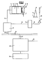
- the device comprises a white light lighting means 1 which may advantageously consist of one or more fluorescent tubes, a linear measurement strip 2 provided with a plurality of photodiodes 3 and mounted inside a protective body 4, the assembly defining an optical sensor 5.
- a white light lighting means 1 which may advantageously consist of one or more fluorescent tubes
- a linear measurement strip 2 provided with a plurality of photodiodes 3 and mounted inside a protective body 4, the assembly defining an optical sensor 5.
- the bottles to be checked such as the bottle 6, move on a conveyor belt shown schematically at 7 perpendicular to the plane of the figure.
- the longitudinal axis of the measuring bar 2 is therefore orthogonal to the movement of the bottles 6.
- the light source 1 is advantageously constituted by a fluorescent tube whose longitudinal axis is parallel to that of the bar 2.
- a protective cover not shown in the figure can advantageously be provided to start the light source 1 and keep it under compressed air pressure to avoid the penetration of dust.
- Figure 1 illustrates by way of example an application of the method of the invention to measure the height of the bottles 8 so as to detect a possible height defect.
- the optical sensor 5 and the light source 1 will be placed in a different way so as to best appreciate the fault considered.
- the essential for the application of the method of the invention is that the longitudinal axis of the measuring bar 2 is orthogonal to the displacement of the bottles 8 so that the combination of the linear arrangement of the photodiodes 3 with the orthogonal displacement of the bottles 8 makes it possible to obtain, by the simple means that constitutes the measuring strip 2, an analysis and a pattern recognition by digital processing of the image provided by the photodiodes as a function of the displacement of the bottles.
- the measuring bar 2 is also placed at the focal point of a focusing objective 9.
- the signals emitted by the photodiodes 3 are amplified or processed by the amplification block 10.
- the sensor 5 also comprises a transmission-reception assembly 11 connected by the connection 12 to the interface 13 which acts by the connection 14 on the power and power control 15 of the light source 1.
- the power control is connected by connection 16 to the amplifier 17 itself connected by connection 18 to the lamp 1.
- a processing computer 20 is connected by the connections 21, 22 and 23 to the interface 13. Dialog with the processing computer 20 is possible via the keyboard 24. Furthermore, the processing computer 20 is capable of sending control signals to the programmable automaton which controls the injection-blowing machine for the bottles 8 via the connection 25.
- the analog amplifier block 10 receives the signals from the measuring strip 2 placed as it was said in the focal plane of the objective 9.
- the network is supplied by two DC voltages -10 and +5 volts and two digital signals : the start signal conveyed by connection 26 and the clock signal conveyed by connection 27.
- the network delivers trains of pulses synchronous with the start and clock signals amplified by a fast operational amplifier 28 connected by connection 29 to the bar of measure 2.
- the signal from the amplifier28 is integrated into an integration circuit comprising a voltage-current converter 30 connected by the connection 31 to the amplifier 28 and an integration capacitor 32 at the terminals of which is mounted a static switch fast 33.
- the signal appearing at the output of the capacitor 32 on the connection 34 feeds a fast comparator 35 through one of its inputs.
- the threshold of this comparator is fixed by the output 36 of a digital / analog converter 37. After each pulse appearing at the input of the capacitor 32, the latter is discharged by the static switch 33 supplied with a reset signal RAZV carried by the connection 39.
- the analog threshold of the digital / analog converter 37 is fixed by the digital value at the input itself defined by a serial transfer at the input of the shift register 40 to the serial input and parallel output connected to the network by the link 41 and receiving the clock signal via connection 42.
- the various signals on transmission and on reception pass through a module 43 for transmitting / receiving lines.
- the assembly is further completed by a voltage regulating device 44.
- the sensor 5 is associated with a computer card 45 having a line transmission-reception system 46 connected to the transceiver 43 as well as a voltage pre-regulation device 47 connected to the regulator 44.
- the sensor 5 is connected to the computer card by cables 48 and 49 which include twisted pairs for the electrical signals (cables 48) and single wires for the power supplies (cables 49).
- the voltage pre-regulator 47 is supplied at 400 Hz using a non-radiating toroidal transformer 50 connected to the general 24 V 400 Hz power line referenced 51 via the connection 52.
- the computer card has a central processing unit 53 with a large random access memory and a read only memory as illustrated in the figure.
- the computer card is connected to a 5-volt supply line referenced 54 for supplying the integrated circuits.
- the computer card 45 is also connected to a local decision bus 55 and to a general data transfer bus 56.
- the signals supplied by the central unit 53 are transmitted by the connection 57 to a shaping block 58 then by the connection 59 to a lighting power card referenced 60 as a whole.
- the latter comprises a serial / parallel shift register referenced 61 connected to a digital-analog converter 62.
- the output signal amplified by the power amplifier 63 is then transmitted via a voltage-frequency converter 64 connected by connection 65 to the lighting source 1.
- the lighting power card 60 is connected by connection 66 to the lightning power line 67 at 30 volts.
- the variation in voltage at the input of the converter 64 causes variations in intensity of the fluorescent tube 1. It is thus possible to obtain a regulated power in order to avoid possible harmful saturation of the photodiodes.
- the converter 64 supplies the tube 1 with high frequency current for example of the order of 25,000 Hz in order to use the remanence of the light discharge in the tube 1 to obtain a continuous light emission, that is to say without scintillation.
- the first signal at the top of the figure is the clock signal which operates the shift register 40 of the photodiodes array 2, with the signal start which is the second from the top in Figure 3.
- the signal appearing at connection 31 at the output of amplifier 28 cannot be used directly.
- the signal RAZV applied to the gate of the switch 33 provides the signal appearing on the connection 34.
- This signal enters the comparator 35 where it is compared with the threshold voltage 36 (straight line 68 in FIG. 3), so as to provide the signals referenced data coming from the comparator 35 conveyed by the connection 69. These are the digital signals which are then transferred to the computer card 45.
- FIG. 4 shows a practical embodiment of the sensor 5. Or found in FIG. 4 the focusing objective 9 and the array of photodiodes 2 arranged in the focal plane of the objective 9.
- the array 2 is directly fixed on the plate 70 screwed into the objective holder 71.
- the analog processing and amplification circuit is mounted on the plate 70.
- the objective 9 is fixed to the objective holder 71 by means of an adapter ring 72 and to the screw means 73.
- the amplified signals are transmitted by the connection 74 to the transceiver card 11.
- the signals after transformation are transmitted by the electronic connection cable 75, the end piece 76 of which is integral with a radial plate 77 body mounted 78.
- an anti-caloric filter 79 disposed in a filter-holder block 80.
- the array of photodiodes 3 is indeed very sensitive to near infrared. If the check is made on radiant objects in the wavelength zone close to the micron, such as for example glass bottles leaving the mold, it is advisable to use such a filter so that this radiation does not come to disturb reception of the light radiation emitted in the visible by the source 1.
- a dust extraction chamber 81 with a cylindrical wall is mounted at the front end of the sensor 5. It comprises, as can be seen in FIG. 5, a front shutter wall 82 provided with an open slot 82a arranged in a diameter.
- a cylindrical sleeve 84 surrounds the body of the sensor 5 leaving a gap 84a.
- a pressurized air supply chamber referenced 85 is located at the rear part of the sensor 5 and is delimited at the rear by a front partition 86 provided with a pressurized air inlet orifice 87.
- the air fed by the orifice 87 enters through the radial holes 88 in the annular interval 84a and flows in this interval thus producing a cooling of the sensor.
- Holes 89 drilled in the filter holder 80 open in the interval 84a and in the dusting chamber 81 by putting the latter under overpressure. In this way, it is avoided that external dust cannot interfere with the operation of the sensor.
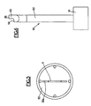
- a standard object is used, illustrated in FIG. 6 and referenced 90 as a whole.
- the total height of the standard 90 corresponds substantially to the height of a bottle. More precisely, it can be seen that the standard 90 comprises a base 91 and a rod 92 at the top of which is a projection 93 over half the thickness of the rod 92. This thus defines a low level 94 and a high level 95.
- the difference in levels can be, for example, in the order of 20 mm.
- the average height of a high temperature bottle as it leaves the manufacturing machine is located at equal distance from levels 94 and 95.
- the device then operates in the following manner, with reference to FIGS. 1 and 6.
- the standard object 90 is placed on the conveyor belt 1 so that the projecting upper part 96 provided with the two surfaces 94 and 95 is presented from the front between the measuring strip 2 and the light source 1.
- the projecting part 93 therefore masks by its solid part located below level 94 a certain number of photodiodes of the strip measure 2. When the movement continues, more photodiodes are hidden by the solid part below level 95.
- the computer notes the time Te. Knowing then the time intervals which elapse between the manufacture of each bottle, the computer can have deduced, taking into account information relating to the initial position of the standard, the exact origin of each bottle measured. In other words, the computer is able to identify which section of the molding machine has produced a particular bottle on which a defect is detected. As a result, the computer is also capable of supplying a control signal to the machine control automaton in order to modify an operating characteristic as a function of the fault detected for a determined section of the molding machine.
- the measurement is made by determining the passage of each bottle the number of hidden diodes. At the time of the measurement, the time when the measurement is made is also indicated and stored in the processing computer. The actual height measurement is calculated by the computer as a function of the number of obscured photodiodes and knowing the exact height of the two levels 94 and 95 of the standard bottle 90. The sections of the molding machine are identified by calculation of the time interval elapsed when a particular bottle passed.
- the central unit 53 checks whether the level of the signal appearing on the connection 34 at the input of the comparator 35 (FIG. 2) is above or below the threshold selected. In the case where the level is lower than the selected threshold, the central unit transmits through the power card 60 an additional voltage unit, which increases the brightness of the source 1. In the case where the level is higher, the on the contrary, the central unit transmits a signal tending to reduce the intensity of the lighting of source 1.
- the method of the invention thus allows not only a quality control made hot immediately at the outlet of the manufacturing machine, but also automatic regulation by feedback on the very operation of the manufacturing machine.
- the method of the invention achieves an approximation of a shape recognition thanks to the use of a plurality of photodiodes arranged in a linear strip orthogonally to the movement of the objects to be checked.
- the invention it becomes possible to carry out, when hot, a plurality of checks on the bottles.
- One can in particular by an analysis of the general shape of each bottle detect bottles stuck to each other or lying on the conveyor belt.
- One can also detect by an analysis of the shape of the bottles, the bottles too small or inclined on the vertical.
- the ejection of defective bottles can be ordered and, if the incident is repeated for a specific section of the manufacturing machine, feed back directly to the manufacturing machine in order to eliminate this incident. It is also possible, thanks to the invention, to count the bottles produced by each section and to directly measure the real speed of the conveyor belt.
Landscapes
- Physics & Mathematics (AREA)
- General Physics & Mathematics (AREA)
- Health & Medical Sciences (AREA)
- Chemical & Material Sciences (AREA)
- Life Sciences & Earth Sciences (AREA)
- General Health & Medical Sciences (AREA)
- Analytical Chemistry (AREA)
- Biochemistry (AREA)
- Engineering & Computer Science (AREA)
- Immunology (AREA)
- Pathology (AREA)
- Quality & Reliability (AREA)
- Automation & Control Theory (AREA)
- Medicinal Chemistry (AREA)
- Food Science & Technology (AREA)
- Investigating Materials By The Use Of Optical Means Adapted For Particular Applications (AREA)
- Re-Forming, After-Treatment, Cutting And Transporting Of Glass Products (AREA)
- Forging (AREA)
- Extrusion Moulding Of Plastics Or The Like (AREA)
- Communication Control (AREA)
- Auxiliary Devices For And Details Of Packaging Control (AREA)
- Crystals, And After-Treatments Of Crystals (AREA)
Claims (12)
- Verfahren zur kontaktlosen automatischen Qualitätskontrolle von mittels einer automatisch gesteuerten Formungsmaschine in hoher Geschwindigkeit hergestellten, aus Kunststoffmaterial oder insbesondere aus Glas hoher Temperatur geformten Gegenständen, wobei in dem Verfahren: sich die Gegenstände vor einer merklichen Abkühlung auf einem Transportband (7) an einer am Ausgang der Formungsmaschine befindlichen optischen Erfassungseinrichtung (5) vorbei verschieben; man die Gegenstände bei ihrer Verschiebung mittels eines Strahlenbündels (1) beleuchtet; man das transmittierte Licht mittels der optischen Erfassungseinrichtung (5) erfaßt, die mit einer eine Anzahl von Empfangsphotodioden (3) umfassenden linearen stabförmigen Meßanordnung (2) versehen ist, wobei die stabförmige Anordnung (2) mit ihrer longitudinalen Achse orthogonal zur Verschiebungsrichtung der Gegenstände (6) und im Brennpunkt eines Abbildungsobjektivs (9) angeordnet ist; man das Ergebnis der Erfassung für eine bestimmte Anzahl von geformten Gegenständen abspeichert; und man in Abhängigkeit von den abgespeicherten Daten periodisch auf eine Prozessteuereinrichtung der Formungsmaschine einwirkt, um die erfaßten Fehler bei der Herstellung der geformten Gegenstände zu eliminieren.
- Verfahren nach Anspruch 1 dadurch gekennzeichnet, daß man die Versorgungsleistung der Lichtquelle (1) in Abhängigkeit vom Ergebnis der Erfassung derart regelt, daß eine Sättigung der Photodioden vermieden wird.
- Verfahren nach einem der vorhergehenden Ansprüche, dadurch gekennzeichnet, daß man nach dem Durchgang jedes Gegenstandes die Meßfrequenz der Erfassungseinrichtung unter Verminderung der Lichtempfindlichkeit erhöht, man dann das empfangene Signal mit einer vorgegebenen Schwelle vergleicht und die Leistung der Lichtquelle erhöht, wenn das Niveau geringer als die vorgegebene Schwelle ist, und man die Intensität der Lichtquelle vermindert, wenn das Niveau die vorgegebene Schwelle übersteigt.
- Automatisches Kontrollverfahren nach einem der vorhergehenden Ansprüche, dadurch gekennzeichnet, daß die Initialisierung der Messung erfolgt, indem man die Verschiebung eines Standardgegenstandes (90) mit bekannten Eigenschaften an der Meßvorrichtung (5) vorbei bewirkt.
- Vorrichtung zur kontaktlosen Kontrolle zur Erfassung von Fehlern bei der Herstellung von mittels einer automatisch gesteuerten Formungsmaschine in hoher Geschwindigkeit hergestellten, aus Kunststoffmaterial oder insbesondere aus Glas hoher Temperatur geformten Gegenständen, bei der sich die Gegenstände vor einer merklichen Abkühlung auf einem Transportband an einer am Ausgang der Formungsmaschine befindlichen optischen Erfassungseinrichtung vorbei verschieben, wobei die Vorrichtung enthält: eine Einrichtung zur Beleuchtung der Gegenstände bei ihrer Verschiebung vorbei an der optischen Erfassungseinrichtung, welche mit einer eine Anzahl von Empfangsphotodioden (3) umfassenden, mit ihrer longitudinalen Achse orthogonal zur Verschiebungsrichtung der Gegenstände (6) angeordneten linearen stabförmigen Meßanordnung (2) versehen ist; ein Abbildungsobjektiv (9), in dessen Brennpunkt die stabförmige Meßanordnung (2) angeordnet ist; eine Datenverarbeitungseinrichtung (20) zur Aufnahme und Abspeicherung einer vorgegebenen Anzahl von durch die stabförmige Meßanordnung gelieferten Signalen; und Mittel zur Verbindung (25) zwischen der Datenverarbeitungseinrichtung (20) und der automatischen Steuerung der Formungsmaschine in der Weise, daß die Herstellung in Abhängigkeit von den abgespeicherten Messungen modifiziert werden kann, um die erfaßten Fehler bei der Herstellung der geformten Gegenstände zu eliminieren.
- Vorrichtung nach Anspruch 5, bei der die Beleuchtungseinrichtung eine Fluoreszenzröhre ist, deren longitudinale Achse sich parallel zu der der stabförmigen Meßanordnung befindet, wobei die Beleuchtungseinrichtung mit elektrischem Strom geregelter Stärke und einer die Remanenz der Fluoreszenzröhre übersteigenden Frequenz gespeist wird.
- Vorrichtung nach einem der Ansprüche 5 oder 6, dadurch gekennzeichnet, daß die Datenverarbeitungseinrichtung (20) Mittel zum Abspeichern der von den verschiedenen Photodioden (3) der stabförmigen Meßanordnung (2) herstammenden Signale und einen Steuerausgang (14) zur Regulierung der Versorgung der Beleuchtungseinrichtung (1) in Abhängigkeit von einer der Sättigung der Photodioden entsprechenden Schwelle umfaßt.
- Vorrichtung nach einem der Ansprüche 5 bis 7, gekennzeichnet durch eine der stabförmigen Meßanordnung (2) zugeordnete Sender-Empfänger-Baugruppe (11), die einen die Folge der von den Photodioden (3) der stabförmigen Meßanordnung (2) abgegebenen Signale und eine Folge von Schwellwertsignalen (36) gleichzeitig aufnehmenden Vergleicher (35) und ein einem mit dem Vergleicher (35) zur Zuführung der oben erwähnten Schwellwertsignale zu diesem gekoppelten Digital/Analog-Wandler (37) zugeordnetes serielles/paralleles Schieberegister (40) umfaßt, wobei der Vergleicher (35) jedesmal ein Ausgangssignal abgibt, wenn das durch eine Photodiode (3) abgegebene Signal das gelieferte Schwellwertsignal überschreitet.
- Vorrichtung nach Anspruch 8, dadurch gekennzeichnet, daß die Sender-Empfänger-Baugruppe weiterhin eine Schalteinrichtung (33) zum Zurücksetzen des Eingangssignals des Vergleichers (35) auf Null enthält.
- Vorrichtung nach einem der Ansprüche 5 bis 9, dadurch gekennzeichnet, daß sie einen die stabförmige Meßanordnung (2), das Abbildungsobjectiv (9) und die elektronischen Schaltungen aufnehmenden Schutzkörper (71) aufweist, wobei ein Ende des Körpers eine Staubschutzkammer (81) bildet, die mit einer einen parallel zu der stabförmigen Meßanordnung (2) angeordneten offenen Schlitz (82a) aufweisenden Verschlußwand (82) versehen ist.
- Vorrichtung nach Anspruch 10, dadurch gekennzeichnet, daß zwischen der Staubschutzkammer (81) und dem Objektiv (9) ein Wärmeschutzfilter (79) angebracht ist.
- Vorrichtung nach den Ansprüchen 10 oder 11, dadurch gekennzeichnet, daß der Schutzkörper von einer einen dazwischen befindlichen Kühlzwischenraum, in dessen Innerem ein Strom von Druckluft zirkulieren kann, begrenzenden Hülse (84) umgeben ist, wobei der Zwischenraum mit der Staubschutzkammer (81) kommuniziert, die somit ebenfalls unter Überdruck gesetzt ist.
Priority Applications (1)
| Application Number | Priority Date | Filing Date | Title |
|---|---|---|---|
| AT85112366T ATE76858T1 (de) | 1984-10-02 | 1985-09-30 | Verfahren und vorrichtung zur kontaktloser kontrolle von, in hoher geschwindigkeit, automatisch hergestellten gegenstaenden. |
Applications Claiming Priority (2)
| Application Number | Priority Date | Filing Date | Title |
|---|---|---|---|
| FR8415117A FR2571143B1 (fr) | 1984-10-02 | 1984-10-02 | Procede et dispositif de controle sans contact d'objets fabriques automatiquement a haute cadence |
| FR8415117 | 1984-10-02 |
Publications (3)
| Publication Number | Publication Date |
|---|---|
| EP0177004A2 EP0177004A2 (de) | 1986-04-09 |
| EP0177004A3 EP0177004A3 (en) | 1988-08-31 |
| EP0177004B1 true EP0177004B1 (de) | 1992-06-03 |
Family
ID=9308268
Family Applications (1)
| Application Number | Title | Priority Date | Filing Date |
|---|---|---|---|
| EP85112366A Expired - Lifetime EP0177004B1 (de) | 1984-10-02 | 1985-09-30 | Verfahren und Vorrichtung zur kontaktloser Kontrolle von, in hoher Geschwindigkeit, automatisch hergestellten Gegenständen |
Country Status (6)
| Country | Link |
|---|---|
| US (1) | US4694158A (de) |
| EP (1) | EP0177004B1 (de) |
| AT (1) | ATE76858T1 (de) |
| DE (1) | DE3586158T2 (de) |
| ES (1) | ES8607543A1 (de) |
| FR (1) | FR2571143B1 (de) |
Cited By (1)
| Publication number | Priority date | Publication date | Assignee | Title |
|---|---|---|---|---|
| DE10116665B4 (de) * | 2001-04-04 | 2015-10-29 | Krones Aktiengesellschaft | Verfahren zur Steuerung eines Blasvorgangs bei der Herstellung von Behältern aus einem thermoplastischen Material |
Families Citing this family (35)
| Publication number | Priority date | Publication date | Assignee | Title |
|---|---|---|---|---|
| US4996658A (en) * | 1989-08-31 | 1991-02-26 | Emhart Industries, Inc. | Self-calibrating glass container inspection machine |
| FR2670908A1 (fr) * | 1990-12-21 | 1992-06-26 | Saint Gobain Vitrage Int | Dispositif de detection sans contact de feuilles de verre en mouvement. |
| FR2681133A1 (fr) * | 1991-09-11 | 1993-03-12 | Languedoc Verrerie | Dispositif d'emission ou d'absorption de lumiere pour le controle sans contact d'objets. |
| FR2683372B1 (fr) * | 1991-10-30 | 1994-02-04 | Languedoc Cie Verrerie | Chassis de montage pour dispositifs de controle sans contact d'objets moules, notamment en verre, a haute temperature. |
| US6584805B1 (en) * | 1993-08-24 | 2003-07-01 | Coors Brewing Company | Hot bottle inspection apparatus |
| NL9301568A (nl) * | 1993-09-09 | 1995-04-03 | Tce Consultancy & Eng | Analyse-systeem voor het analyseren, bewaken, diagnostiseren en/of sturen van een produktieproces waarin produkten worden gevormd die een temperatuurbehandeling ondergaan, produktieproces met een analysesysteem en een werkwijze daarvoor. |
| FR2712089B1 (fr) * | 1993-11-02 | 1996-02-09 | Souchon Neuvesel Verreries | Dispositif de contrôle optique de la qualité d'articles transparents ou translucides. |
| EP0742432A1 (de) * | 1995-05-10 | 1996-11-13 | Verreries Souchon Neuvesel - Vsn | Vorrichtung zur optischen Qualitätskontrolle von durchsichtigen oder durchscheinenden Gegenständen |
| US6025910A (en) * | 1995-09-12 | 2000-02-15 | Coors Brewing Company | Object inspection method utilizing a corrected image to find unknown characteristic |
| AU6640396A (en) * | 1995-07-31 | 1997-02-26 | Coors Brewing Company | Hot bottle inspection apparatus and method |
| JP2002513463A (ja) * | 1996-06-04 | 2002-05-08 | イネックス・インコーポレイテッド・ドゥーイング・ビジネス・アズ・イネックス・ビジョン・システムズ・インコーポレイテッド | 成形容器内の応力検出システムおよび方法 |
| US6118526A (en) * | 1996-08-16 | 2000-09-12 | Coors Brewing Company | Method for measurement of light transmittance |
| US6025919A (en) * | 1996-08-16 | 2000-02-15 | Coors Brewing Company | Method for measurement of light transmittance |
| DE19651924A1 (de) * | 1996-12-13 | 1998-06-18 | Dieter Olschewski | Behälterglasprüfverfahren und -vorrichtungen |
| US5896195A (en) * | 1997-05-15 | 1999-04-20 | Owens-Brockway Glass Container Inc. | Container sealing surface area inspection |
| US5935285A (en) * | 1997-12-30 | 1999-08-10 | Coors Brewing Company | Method for inspecting manufactured articles |
| US6049379A (en) * | 1997-12-30 | 2000-04-11 | Coors Brewing Company | Method for inspecting translucent objects using imaging techniques |
| US5917602A (en) * | 1998-04-30 | 1999-06-29 | Inex Inc. | System and method for image acquisition for inspection of articles on a moving conveyor |
| US6256095B1 (en) | 2000-01-21 | 2001-07-03 | Owens-Brockway Glass Container Inc. | Container sealing surface area inspection |
| WO2001065204A1 (en) * | 2000-03-01 | 2001-09-07 | Plastic Technologies, Inc. | Method and apparatus for measuring wall thickness of a plastic container |
| DE10030649A1 (de) * | 2000-06-29 | 2002-01-10 | Michael Kaufmann | Verfaren zur Erfassung,Diagnose,Überwachung und Regelung von Formgebungseigen- chaften an Glasformmaschinen mit mehreren Stationen |
| US6822181B2 (en) * | 2001-06-27 | 2004-11-23 | Labatt Brewing Company Limited | Container diverter |
| DE10141540C1 (de) * | 2001-08-24 | 2002-12-12 | Hermann Heye I I | Verfahren und Vorrichtung zum Abtransport von Glasbehältern aus einer Glasformmaschine |
| GB0326696D0 (en) * | 2003-11-15 | 2003-12-17 | Sencon Europ Ltd | Process for retrospective rejection of defective objects |
| US7534378B2 (en) * | 2004-03-03 | 2009-05-19 | Rexam Prescription Products Inc. | Plastic forming process monitoring and control |
| FR2881979B1 (fr) † | 2005-02-17 | 2007-04-27 | Sidel Sas | Procede de commande d'une machine de soufflage de recipients visant a corriger des anomalies dans la repartition de matiere |
| DE102008054109A1 (de) * | 2008-10-31 | 2010-05-12 | Khs Ag | Verfahren und Vorrichtung zur Identifizierung von Gegenständen |
| US9233868B2 (en) * | 2011-02-23 | 2016-01-12 | Emhart Glass S.A. | System and method for controlling pusher parameters to adjust the placement of glass containers on the conveyor |
| DE102013106894A1 (de) * | 2013-07-01 | 2015-01-08 | Krones Ag | Behälterinspektionsvorrichtung und Behälterinspektionsverfahren zur Inspektion von Behältern |
| FR3056296B1 (fr) * | 2016-09-19 | 2018-10-19 | Tiama | Installation pour l'inspection optique de recipients en verre en sortie de machine de formage |
| FR3056297B1 (fr) | 2016-09-19 | 2018-10-05 | Tiama | Dispositif pour l'inspection optique de recipients en verre en sortie de machine de formage |
| FR3102703B1 (fr) * | 2019-10-30 | 2021-11-12 | Sidel Participations | Procédé de contrôle d’un récipient en matière plastique et machine de fabrication d’un tel récipient |
| US20220288828A1 (en) * | 2021-03-12 | 2022-09-15 | Nexe Innovations Inc. | Thermoplastic article forming and annealing apparatus |
| FR3131634B1 (fr) | 2021-12-30 | 2024-01-05 | Tiama | Procédé et dispositif d’inspection de récipients chauds en verre en vue d’identifier des défauts |
| FR3157935A1 (fr) * | 2023-12-28 | 2025-07-04 | Tiama | Procédé de contrôle d’une installation de fabrication de récipients en verre en secteur chaud par obtention d’une image |
Family Cites Families (20)
| Publication number | Priority date | Publication date | Assignee | Title |
|---|---|---|---|---|
| US3762907A (en) * | 1971-02-22 | 1973-10-02 | Ball Corp | Glass forming machine having an automatic control system |
| JPS5628650B2 (de) * | 1973-06-18 | 1981-07-03 | ||
| US4145204A (en) * | 1977-12-01 | 1979-03-20 | Owens-Illinois, Inc. | Timing pulse generator for a glassware forming machine |
| US4247317A (en) * | 1978-04-20 | 1981-01-27 | Ball Corporation | Glassware forming machine computer-ram controller system |
| US4254364A (en) * | 1979-05-04 | 1981-03-03 | Bell & Howell Company | Lamp regulator circuit for rotary camera |
| FR2475424A1 (fr) * | 1980-02-12 | 1981-08-14 | Supermarket System | Procede et appareil d'identification de bouteilles |
| US4391373A (en) * | 1980-11-10 | 1983-07-05 | Barry-Wehmiller Company | Method of and apparatus for compensating signal drift during container inspection |
| FR2500630A1 (fr) * | 1981-02-25 | 1982-08-27 | Leser Jacques | Procede pour la recherche des defauts des feuilles de verre et dispositif mettant en oeuvre ce procede |
| EP0059572B1 (de) * | 1981-02-27 | 1985-03-06 | Emhart Industries, Inc. | Verfahren zum Observieren eines Glasverarbeitungszyklus |
| GB2093821B (en) * | 1981-02-27 | 1984-09-26 | Emhart Uk Ltd | Glassware-forming machine with faultdetection and control |
| US4354865A (en) * | 1981-05-01 | 1982-10-19 | Brockway Glass Company, Inc. | Automatic glass ware forming machine with automatic down and/or stuck bottle rejection |
| US4476533A (en) * | 1981-07-08 | 1984-10-09 | Ball Corporation | Glassware gauging system |
| US4453963A (en) * | 1982-07-29 | 1984-06-12 | Emhart Industries, Inc. | Method and apparatus for controlling the delivery of gobs to a section of a glassware forming machine |
| US4475937A (en) * | 1982-09-01 | 1984-10-09 | Glasstech, Inc. | Conveyor controller for glass sheet processing equipment |
| US4533053A (en) * | 1983-01-13 | 1985-08-06 | Magnetic Separation Systems, Inc. | Rotary drum magnetic separator |
| IE830387L (en) * | 1983-02-23 | 1982-08-16 | Udaras Na Gaeltachta | Inspection apparatus for translucent containers |
| US4533854A (en) * | 1983-03-25 | 1985-08-06 | Xerox Corporation | Mechanism and method for controlling the temperature and output of a fluorescent lamp |
| US4529912A (en) * | 1983-03-25 | 1985-07-16 | Xerox Corporation | Mechanism and method for controlling the temperature and light output of a fluorescent lamp |
| US4494656A (en) * | 1983-04-01 | 1985-01-22 | Powers Manufacturing, Inc. | Down and stuck ware inspection method and apparatus |
| US4529429A (en) * | 1983-05-06 | 1985-07-16 | Ball Corporation | Digital glass forming machine |
-
1984
- 1984-10-02 FR FR8415117A patent/FR2571143B1/fr not_active Expired
-
1985
- 1985-09-30 DE DE8585112366T patent/DE3586158T2/de not_active Expired - Lifetime
- 1985-09-30 EP EP85112366A patent/EP0177004B1/de not_active Expired - Lifetime
- 1985-09-30 AT AT85112366T patent/ATE76858T1/de not_active IP Right Cessation
- 1985-10-01 US US06/782,336 patent/US4694158A/en not_active Expired - Lifetime
- 1985-10-02 ES ES547486A patent/ES8607543A1/es not_active Expired
Cited By (1)
| Publication number | Priority date | Publication date | Assignee | Title |
|---|---|---|---|---|
| DE10116665B4 (de) * | 2001-04-04 | 2015-10-29 | Krones Aktiengesellschaft | Verfahren zur Steuerung eines Blasvorgangs bei der Herstellung von Behältern aus einem thermoplastischen Material |
Also Published As
| Publication number | Publication date |
|---|---|
| ES547486A0 (es) | 1986-06-16 |
| FR2571143B1 (fr) | 1988-03-25 |
| US4694158A (en) | 1987-09-15 |
| FR2571143A1 (fr) | 1986-04-04 |
| ATE76858T1 (de) | 1992-06-15 |
| ES8607543A1 (es) | 1986-06-16 |
| DE3586158T2 (de) | 1992-12-03 |
| EP0177004A3 (en) | 1988-08-31 |
| EP0177004A2 (de) | 1986-04-09 |
| DE3586158D1 (de) | 1992-07-09 |
Similar Documents
| Publication | Publication Date | Title |
|---|---|---|
| EP0177004B1 (de) | Verfahren und Vorrichtung zur kontaktloser Kontrolle von, in hoher Geschwindigkeit, automatisch hergestellten Gegenständen | |
| US6835939B2 (en) | Missing lens detection system and method | |
| FR2538904A1 (fr) | Detection optique de defauts radiaux a effet reflechissant | |
| CA2442737C (fr) | Dispositif et procede d'inspection automatique d'objets defilant en flux sensiblement monocouche | |
| EP0034088B1 (de) | Apparat zur Erkennung von Gegenständen, wie z.B. Flaschen | |
| EP3423202B1 (de) | Inspektionsmmaschine und verfahren für sich in einem materialfluss bewegende objekte | |
| CH633104A5 (fr) | Procede et appareil pour mesurer l'epaisseur d'une paroi d'un objet en plastique. | |
| EP3963284B1 (de) | Linie zur inspektion von leeren glasbehältern | |
| FR2499719A1 (fr) | Appareil pour verifier la paroi laterale de recipients en verre | |
| FR2645310A1 (fr) | Procede d'identification d'objets en mouvement, notamment de vehicules, et systemes pour sa mise en oeuvre | |
| US6548818B1 (en) | Missing lens detection system and method | |
| EP3997416A1 (de) | Vorrichtung und verfahren zum messen der dicke der wände von glasbehältern | |
| FR2884317A1 (fr) | Procede et dispositif pour supprimer les reflets parasites lors de l'inspection a chaud d'objets creux translucides ou transparents | |
| FR2683791A3 (fr) | Dispositif pour le controle optique de produits sosu emballage. | |
| EP1147405B1 (de) | Verfahren und vorrichtung zur erfassung von rissen in gegenständen aus durchsichtigem oder lichtdurchlässigem material | |
| WO2001055705A1 (fr) | Installation et procede pour la detection de glacures | |
| FR2512945A1 (fr) | Procede de | |
| FR2520267A1 (fr) | Machine pour la deconsignation d'objets tels que des bouteilles | |
| WO2000009987A1 (fr) | Dispositif de mesure de la taille de particules en deplacement, notamment pour des mesures pluviometriques | |
| AU5827299A (en) | Missing lens detection system and method | |
| AU2005202395B2 (en) | Missing lens detection system and method | |
| FR3105396A1 (fr) | Dispositif et procédé de mesure de l'épaisseur de la paroi d'un récipient | |
| FR2488156A2 (fr) | Procede et appareil d'identification de bouteilles | |
| HK1027788B (en) | Missing contact lens detection system and method |
Legal Events
| Date | Code | Title | Description |
|---|---|---|---|
| PUAI | Public reference made under article 153(3) epc to a published international application that has entered the european phase |
Free format text: ORIGINAL CODE: 0009012 |
|
| AK | Designated contracting states |
Kind code of ref document: A2 Designated state(s): AT BE CH DE FR GB IT LI LU NL SE |
|
| PUAL | Search report despatched |
Free format text: ORIGINAL CODE: 0009013 |
|
| AK | Designated contracting states |
Kind code of ref document: A3 Designated state(s): AT BE CH DE FR GB IT LI LU NL SE |
|
| 17P | Request for examination filed |
Effective date: 19881003 |
|
| 17Q | First examination report despatched |
Effective date: 19890627 |
|
| GRAA | (expected) grant |
Free format text: ORIGINAL CODE: 0009210 |
|
| AK | Designated contracting states |
Kind code of ref document: B1 Designated state(s): AT BE CH DE FR GB IT LI LU NL SE |
|
| REF | Corresponds to: |
Ref document number: 76858 Country of ref document: AT Date of ref document: 19920615 Kind code of ref document: T |
|
| REF | Corresponds to: |
Ref document number: 3586158 Country of ref document: DE Date of ref document: 19920709 |
|
| GBT | Gb: translation of ep patent filed (gb section 77(6)(a)/1977) | ||
| ITF | It: translation for a ep patent filed | ||
| PLBE | No opposition filed within time limit |
Free format text: ORIGINAL CODE: 0009261 |
|
| STAA | Information on the status of an ep patent application or granted ep patent |
Free format text: STATUS: NO OPPOSITION FILED WITHIN TIME LIMIT |
|
| 26N | No opposition filed | ||
| EPTA | Lu: last paid annual fee | ||
| ITTA | It: last paid annual fee | ||
| EAL | Se: european patent in force in sweden |
Ref document number: 85112366.1 |
|
| PGFP | Annual fee paid to national office [announced via postgrant information from national office to epo] |
Ref country code: SE Payment date: 19980923 Year of fee payment: 14 |
|
| PGFP | Annual fee paid to national office [announced via postgrant information from national office to epo] |
Ref country code: AT Payment date: 19980928 Year of fee payment: 14 |
|
| PGFP | Annual fee paid to national office [announced via postgrant information from national office to epo] |
Ref country code: BE Payment date: 19980930 Year of fee payment: 14 |
|
| PGFP | Annual fee paid to national office [announced via postgrant information from national office to epo] |
Ref country code: LU Payment date: 19981006 Year of fee payment: 14 |
|
| PG25 | Lapsed in a contracting state [announced via postgrant information from national office to epo] |
Ref country code: SE Free format text: THE PATENT HAS BEEN ANNULLED BY A DECISION OF A NATIONAL AUTHORITY Effective date: 19990929 |
|
| PG25 | Lapsed in a contracting state [announced via postgrant information from national office to epo] |
Ref country code: LU Free format text: LAPSE BECAUSE OF NON-PAYMENT OF DUE FEES Effective date: 19990930 Ref country code: BE Free format text: LAPSE BECAUSE OF NON-PAYMENT OF DUE FEES Effective date: 19990930 Ref country code: AT Free format text: LAPSE BECAUSE OF NON-PAYMENT OF DUE FEES Effective date: 19990930 |
|
| BERE | Be: lapsed |
Owner name: VERRERIE DU LANGUEDOC ET CIE Effective date: 19990930 |
|
| EUG | Se: european patent has lapsed |
Ref document number: 85112366.1 |
|
| REG | Reference to a national code |
Ref country code: FR Ref legal event code: TP |
|
| REG | Reference to a national code |
Ref country code: GB Ref legal event code: IF02 |
|
| PGFP | Annual fee paid to national office [announced via postgrant information from national office to epo] |
Ref country code: FR Payment date: 20030902 Year of fee payment: 19 |
|
| PGFP | Annual fee paid to national office [announced via postgrant information from national office to epo] |
Ref country code: GB Payment date: 20030915 Year of fee payment: 19 |
|
| PGFP | Annual fee paid to national office [announced via postgrant information from national office to epo] |
Ref country code: NL Payment date: 20030916 Year of fee payment: 19 |
|
| PGFP | Annual fee paid to national office [announced via postgrant information from national office to epo] |
Ref country code: DE Payment date: 20030930 Year of fee payment: 19 |
|
| PGFP | Annual fee paid to national office [announced via postgrant information from national office to epo] |
Ref country code: CH Payment date: 20031124 Year of fee payment: 19 |
|
| PG25 | Lapsed in a contracting state [announced via postgrant information from national office to epo] |
Ref country code: LI Free format text: LAPSE BECAUSE OF NON-PAYMENT OF DUE FEES Effective date: 20040930 Ref country code: GB Free format text: LAPSE BECAUSE OF NON-PAYMENT OF DUE FEES Effective date: 20040930 Ref country code: CH Free format text: LAPSE BECAUSE OF NON-PAYMENT OF DUE FEES Effective date: 20040930 |
|
| PG25 | Lapsed in a contracting state [announced via postgrant information from national office to epo] |
Ref country code: NL Free format text: LAPSE BECAUSE OF NON-PAYMENT OF DUE FEES Effective date: 20050401 Ref country code: DE Free format text: LAPSE BECAUSE OF NON-PAYMENT OF DUE FEES Effective date: 20050401 |
|
| REG | Reference to a national code |
Ref country code: CH Ref legal event code: PL |
|
| GBPC | Gb: european patent ceased through non-payment of renewal fee |
Effective date: 20040930 |
|
| PG25 | Lapsed in a contracting state [announced via postgrant information from national office to epo] |
Ref country code: FR Free format text: LAPSE BECAUSE OF NON-PAYMENT OF DUE FEES Effective date: 20050531 |
|
| NLV4 | Nl: lapsed or anulled due to non-payment of the annual fee |
Effective date: 20050401 |
|
| REG | Reference to a national code |
Ref country code: FR Ref legal event code: ST |