EP0177107A1 - Plattenspieler - Google Patents
Plattenspieler Download PDFInfo
- Publication number
- EP0177107A1 EP0177107A1 EP85201584A EP85201584A EP0177107A1 EP 0177107 A1 EP0177107 A1 EP 0177107A1 EP 85201584 A EP85201584 A EP 85201584A EP 85201584 A EP85201584 A EP 85201584A EP 0177107 A1 EP0177107 A1 EP 0177107A1
- Authority
- EP
- European Patent Office
- Prior art keywords
- turntable
- disc
- drawer
- housing
- pressure
- Prior art date
- Legal status (The legal status is an assumption and is not a legal conclusion. Google has not performed a legal analysis and makes no representation as to the accuracy of the status listed.)
- Granted
Links
- 230000000717 retained effect Effects 0.000 description 5
- 239000004925 Acrylic resin Substances 0.000 description 1
- 229920000178 Acrylic resin Polymers 0.000 description 1
- 230000008878 coupling Effects 0.000 description 1
- 238000010168 coupling process Methods 0.000 description 1
- 238000005859 coupling reaction Methods 0.000 description 1
- 230000000694 effects Effects 0.000 description 1
- 238000000034 method Methods 0.000 description 1
- 230000002093 peripheral effect Effects 0.000 description 1
- 230000003068 static effect Effects 0.000 description 1
- 229920003002 synthetic resin Polymers 0.000 description 1
- 239000000057 synthetic resin Substances 0.000 description 1
Images




Classifications
-
- G—PHYSICS
- G11—INFORMATION STORAGE
- G11B—INFORMATION STORAGE BASED ON RELATIVE MOVEMENT BETWEEN RECORD CARRIER AND TRANSDUCER
- G11B17/00—Guiding record carriers not specifically of filamentary or web form, or of supports therefor
- G11B17/02—Details
- G11B17/04—Feeding or guiding single record carrier to or from transducer unit
- G11B17/05—Feeding or guiding single record carrier to or from transducer unit specially adapted for discs not contained within cartridges
-
- G—PHYSICS
- G11—INFORMATION STORAGE
- G11B—INFORMATION STORAGE BASED ON RELATIVE MOVEMENT BETWEEN RECORD CARRIER AND TRANSDUCER
- G11B17/00—Guiding record carriers not specifically of filamentary or web form, or of supports therefor
- G11B17/02—Details
- G11B17/022—Positioning or locking of single discs
- G11B17/028—Positioning or locking of single discs of discs rotating during transducing operation
- G11B17/0284—Positioning or locking of single discs of discs rotating during transducing operation by clampers
- G11B17/0285—Positioning or locking of single discs of discs rotating during transducing operation by clampers mounted on a bridge
-
- G—PHYSICS
- G11—INFORMATION STORAGE
- G11B—INFORMATION STORAGE BASED ON RELATIVE MOVEMENT BETWEEN RECORD CARRIER AND TRANSDUCER
- G11B19/00—Driving, starting, stopping record carriers not specifically of filamentary or web form, or of supports therefor; Control thereof; Control of operating function ; Driving both disc and head
- G11B19/20—Driving; Starting; Stopping; Control thereof
- G11B19/2009—Turntables, hubs and motors for disk drives; Mounting of motors in the drive
-
- G—PHYSICS
- G11—INFORMATION STORAGE
- G11B—INFORMATION STORAGE BASED ON RELATIVE MOVEMENT BETWEEN RECORD CARRIER AND TRANSDUCER
- G11B33/00—Constructional parts, details or accessories not provided for in the other groups of this subclass
- G11B33/02—Cabinets; Cases; Stands; Disposition of apparatus therein or thereon
- G11B33/027—Covers
-
- G—PHYSICS
- G11—INFORMATION STORAGE
- G11B—INFORMATION STORAGE BASED ON RELATIVE MOVEMENT BETWEEN RECORD CARRIER AND TRANSDUCER
- G11B33/00—Constructional parts, details or accessories not provided for in the other groups of this subclass
- G11B33/10—Indicating arrangements; Warning arrangements
Definitions
- the invention relates to a disc player, comprising a housing, a rotatable turntable having a non-vertical axis and a pressure member for urging the disc against the turntable which member is positioned coaxially to the axis of the turntable and is movable toward and from the turntable.
- a conventional disc player is known from US 2 007 054 and is constructed with the turntable established in the middle part of the housing.
- the invention has for its object to provide a disc player which is constructed in such a way that the disc from which the recorded information is being reproduced can be seen in its entirety from the outside, with which the words and symbols etc. which are displayed on the said disc can be read even though the disc is being rotated at a fairly high speed.
- the invention is therefore characterized in that the turntable is located in the housing in such position that it is visible viewed at the front of the housing, the turntable is covered with a cover, which has a transparent front surface and which is movably arranged at the front of the housing between an opened and a closed position, the pressure member is located on a pressure arm, which is movable toward and from the turntable, a strobe light emitting device is located on said pressure arm to illuminate the surface of the disc, when it is urged against the turntable.
- the strobe light emitting device is made to emit light at a frequency with the same period as a single rotation of the disc, which is preferably a so called compact disc, then the disc will be illuminated in the same position each time and the disc can be observed easily from the outside while the recorded information is being reproduced.
- the pressure arm is formed as an elongated frame which carries the pressure member in its middle part and has an aperture on either side of the pressure member, the strobe light emitting device comprising two light emitters, which are fitted in said apertures.
- the strobe light emitting device comprising two light emitters, which are fitted in said apertures.
- the player comprises a loading mechanism, having a drawer, which is rectilinearly movable between an opened and a closed position, the drawer carries a disc receiving plate, which is freely movable within a hole of the drawer in upward and downward direction parallel to the axis of rotation of the turntable, which hole has a diameter slightly larger than that of the disc, the arrangement of the pressure arm being such that it can move with the pressure member through said hole during its movement toward and from the turntable.
- the drawer is movable out and in horizontally at the front of the housing and to the disc is given up an accepted via the disc receiving plate which match up with the drawer.
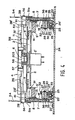
- the front part of a disc player of this invention in the form of a so-called compact disc player, is shown in figure 1.
- the player comprises a housing 1, a player body 2, which is located in such a position as to be visible viewed at the front of the housing, a transparent cylindrically shaped front cover 3 which can be opened and closed freely and which covers the front of the aforementioned housing 1, a pressure equipment 4 and a loading device, formed by a drawer 8,
- the player body 2 is located with a downward inclination of about 25° towards the front relative to the horizontal.
- the player body 2 comprises a turntable 5 and a spindle 6, which are located protruding in the centre of the player body and the turntable 5 is driven round by a motor 5' (see figure 4).
- 2' is an information read out part.
- the front cover 3 is moulded from a highly transparent acrylic resin for example and the shape is curved with an appropriate radius of curvature (for example R about 150 mm) so as to fit as closely as possible to the aforementioned player body 2 in the opening/ closing orientation (the left/right orientation in figure 2) and such that the front can be opened and closed while retaining a compact form.
- the front cover 3 has its side parts engaged so as to slide freely in guide grooves 7', which have the same radius of curvature as the front cover 3 and which are located in side plates 7, 7 of the housing 1.
- the guide grooves 7' have a width slightly greater than the thickness of the front cover 3 and they are established with an extra length L which provides for the opening/closing stroke on the inside, taking a position above the top surface of the front part of the drawer 8 which covers the top of the player body 2 as the cardinal point (figure 2).
- rubber drive rollers 101 are shown of cylindrical form which make a press contact with the inner surface of the front cover 3 and provides a drive device for the opening and closing of the front cover 3.
- a rotating shaft 110 is supported to rotate freely in the side plates 7, 7.
- a gear wheel 102 is fitted to the end of the rotating shaft 110 on the outside of the plate 7 and is engaged with a drive pinion 103 of a motor 104 which is located between the plates 7, 7.
- push rollers 106 are in press contact with the top surface of the front cover 3 at pins opposite to the aforementioned drive rollers 101.
- the rollers 106 are established on the inside of a cover plate 105 which covers over the top of the housing ⁇ (see figure 2).
- the said push rollers 106 are fitted so as to rotate freely on the end of a swinging arm 109 which is itself fitted to rotate freely by a pin 108 to a bracket 107 which is established on the inner surface of the cover plate 105.
- the swinging arm 109 is normally subjected by means of a screw coil spring 200 to a rotating moment which pushes the push rollers 106 in the direction of the front cover 3.
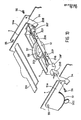
- the overall form of the drawer 8 is shown in figure 5 and it has a through hole 12 located in a position concentric with the turntable 5 and with a diameter some 1 - 2 mm greater than that of a disc 11 in the inclined part which is approximatäo / parallel with the player body 2.
- the said through hole 12 is formed with a cylindrical shape with the edges of the hole in the said drawer 8 folded over some 10 mm to the inside in order to provide a screen which covers the internal mechanism.
- the said disc receiving plates 9 are located inside the aforementioned through hole 12 (see figure 2).
- the said disc receiving plates 9 take the form of crescent shaped plates equivalent to parts of width about 30 mm which have been cut off from a circle of a similar form to the disc 11 (see figure 6) and these plates are established symmetrically on the left and right hand sides inside the through hole 12 (see figure 6) and these plates are established symmetrical on the left and right hand sides inside the through hole 12 (see figure 3).
- the disc receiving plates 9 are moulded from a synthetic resin as one with supporting parts 9' (see figure 6) and the said supporting parts 9' are fitted with screws 14 and fixed to brackets 13', 13' of a raising and lowering plate 13.
- the brackets 13' are formed by folding the upper edges of the raising and lowering plate 13 inwards through an angle of about 90° (see figure 6).
- the raising and lowering plates 13 have two supporting shafts 15, 15 which are fixed left and right facing outwards and these pass through inclined slits 17, 17 which are established with an inclination towards the front of about 45° in left and right hand drive plates 16.
- the supporting shafts 15, 15 also pass through guide slits 21, 21 which are established parallel with the axis of rotation of the turntable 5 in the top part 18a of roughly triangular shaped slide frames 18 and these are fitted with slide washers etc. and stopped from the opposite side.
- guide slits 21, 21 which are established parallel with the axis of rotation of the turntable 5 in the top part 18a of roughly triangular shaped slide frames 18 and these are fitted with slide washers etc. and stopped from the opposite side.
- top edges of top parts 18a are inclined at an angle parallel with the inclination of the player body 2 (see figure 6) and the drive plates 16 slide along inside guide pieces 19 which are formed by folding the said top edges over at right angles (see figure 2).
- the lower edges of the said drive plates 16 are supported in such a way that they are able to slide on pins 20 which are fixed to the top part 18a (see figure 2).
- the slide frames 18 have folded parts 22 which are formed at the lower edge supported so as to be able to slide freely by ball bearings 25 which are retained in fixing jigs 23 which have a roughly Z shaped transverse cross section.
- the ball bearings 25 are such that the folded parts 22 of the slide frames 18 can slide with very little friction, the movement being accompanied by the rotation of the balls 25' on the top of the base 24.
- Arm parts 8a of the above mentioned drawer 8 are fitted and fixed to the outsides of the slide frames 18 with screws 26, 26 and the two parts move in unison.
- Approximately square section gear rack members 27 are established so as to slide freely in the same direction as the slide frames 18 on the top surfaces of the aforementioned fixing jigs 23 (see figure 4).
- pins 28 are shown, which are fitted roughly at right angles facing the inside of the slide frames 18, and which are stationary arranged. Slots 29 are located along the length of the flanks of the rack members 27. The aforementioned pins 28 pass through the said slots 29 and are stopped from this side with slide washers 30 and rings 31 (see figure 4).
- the slots 29 are slightly wider than the external diameter of the pins 28 and they are formed with a length equal to the extent of the movement of the slide frames 18, when moved with the rack members 27.
- First tooth portion 32 are formed along more or less the whole length on about the inner onethird of the top surfaces of the rack members 27 and these are engaged with motive pinions 33.
- the motive pinions 33 are driven by a motor 34 (see figure 7). The positions of the motive pinions are fixed.
- the rack members 27 can be reciprocated at a constant speed by the engagement between the tooth portions 32 and the motive pinions 33 which can be driven forward and in reverse by the motor 34,
- the pins 28 engage with the left or right ends of the slots 29. Consequently the slide frames 18 and the drawer 8 are moved together with the movement of the rack members 27.
- L shaped ball retaining parts 35 are fixed to the inner surfaces ofthe slide frames 18 with horizontal parts 35a parallel to the sliding surfaces of the rack members 27 and the fixing jigs 23.
- a single ball 36 is retained loosely in the centre of the horizontal part 35a of each of the ball retaining parts 25 and the lower halves of the said balls 36 are retained in holes 39 which are established in the fixing jigs 23 (see figure 8).
- deep restricting grooves 37 are provided, which house the upper halves of the said balls 36 such that the balls 36 make length of the sliding width of the grooves 37, which are located along the length of the sliding surfaces of the rack members 27.
- a release concavity 38 of a depth which is able to house the whole of the ball 36 is established at the right hand end of the said restricting groove 37 in figure 8.
- the length of the restricting grooves 37 is equal to the length of the slots 29 in the racks members 27 described above,
- drawer 8 and the disc receiving plates 9 in figure 2 are advanced so as to protrude forwards for the ejection of a disc 11 which has been played or for the fitting of the next disc 11.
- the motive pinions 33 are then driven in reverse and the rack members 27 are moved to the right in figure 8. At this time the movement starts with the balls 36 floated up into the release concavities 38 and so the drawer 8 and the slide frames 18 (and hence the disc receiving plates 9) are moved to the right in unison with the rack members 27. However the drawer 8 and the slide frames 13 are stopped at the position in which the balls 36 enter into the holes 39 of the fixing jigs 23 and then only the rack members 27 move to the right with the surfaces of the balls 36 sliding in the restricting grooves 37, returning to the position which is shown in figure 8.
- second tooth portions 40 and third tooth portions 41 of a prescribed length are formed along the length orientation on the top surfaces of the above mentioned rack members 27, each with a tooth width of about one third of the width of the surface which remains after excluding the tooth po tion 32.
- Secondary gear wheels 42 which engage with the tooth portions 40 are located on the slide frames 18 and pinions 43 which are formed as one with the said secondary gear wheels 42 are engaged with racks 44 which are formed on the bottom edges of the drive plates 16 which were mentioned earlier.
- Tension springs 45 which restrict the rotation of the secondary gear wheels 42 are connected between the secondary gear wheels 42 and pins 18b which are established on the top parts 18a of the slide frames 18.
- the disc receiving plates 9 which are at a position slightly below the disc 11, which has been pressed onto the turntable 5, are raised to a position more or less level with the upper edge of the through hole 12 of the drawer 8 and then stop. Hence the disc 11 which is on the turntable 5 and from which the pressure member has been released by the pressure equipment 4 is lifted up during this process.
- the design is such that the rotation of the secondary gear wheel 42, which is required to provide the abae mentioned lifting stroke for the disc receiving plates 9, is less than 180°.
- the tension springs 45 are stretched and at this time the members 27 are moving in unison with the slide frames 18, so that rotation of the secondary gear wheels 42 is stopped and the disc receiving plates 9 are fixed in the aforementioned raised position.
- Recesses 81 and 91 into which a finger can be inserted easily are located on the right and left hand sides of the drawer 8 and the disc receiving plates 9 in order to facilitate the removal or fitting of the disc 11 (Fig. 3).
- the disc receiving plates 9 are retained in the raised position as the drawer 8 is being retracted (when it is being pulled back in). However as the drawer 8 reaches the limit of its retraction and stops, the secondary gear wheels 42 start to move in engagement with the tooth portions 40. Consequently the drive plates 16 are moved to the right in figure 6 and the raising and lowering plates 13 and the disc receiving plates 9, which are attached to the raising and lowering plates 13, descend along the axis of rotation line of the turntable 5 in the guide slits 21 as a result of the action of the inclined slits 17. That is to say the disc receiving plates 9 sink in the through hole 12, placing the disc 11 on the turntable 5, and then stop on reaching a slightly lower position (see figure 4).
- tooth portion 40 is formed in the position and with the length required to enable to disc receiving plates 9 to be operated in the way described above.
- the pressure equipment 4 comprises a pressure arm 52, which is formed as a hollow framework of long thin plates and which has a width of about 30 mm, a height of about 10 mm and a length of about 200 mm, as shown in detail in figures 4 and 10.
- the hollow part is closed by a cover plate 201.
- a holder chamber 57 which has the form of an up/down orientated cylinder, is formed roughly in the middle part of the pressure arm 52 and a pressure member 58 is located inside the said holder chamber 57.
- the pressure member 58 has a hole 203 of a size which can accommodate the spindle 6 at its centre and a magnet 204 is incorporated into the peripheral parts around this hole.
- the pressure member 58 is located with a certain amount of free play in the up/down direction in order to provide a stroke of a few millimeters inside the holder chamber.
- the pressure member 58 is attracted to the turntable by the effect of the magnet 204 within the range of its free play so that the disc 11 is restrained and held firmly between the pressure member 58 and the turntable 5.
- Two apertures 206, 206 are located at the underside of the above mentioned pressure arm 52 at roughly symmetrical positions on either side of the pressure member 58 and a strobe light emitting device comprising two emitters 207 is fitted facing downwards in the said apertures (see figure 10).
- the strobe light emitters 207, 207 are made to emit light at a frequency which has the same period as the rotation of the disc 11 by means of a synchronising circuit which is not shown in the drawings in the condition where a compact disc 11 is pressed onto the turntable 5 in the way described above, then the disc will be effectively illuminated at the same position on each rotation. Hence it is possible to read the words and symbols etc. which are displayed on the said disc 11 exactly as though it was in a stationary condition.
- the pressure arm 52 has square pillar like supporting arms 208, 208 arranged symmetrically on its two edges. These supporting arms 208 are formed with downward facing protrusions 208' which extend downwards for about 5 millimetres from the lower surface of the pressure arm.
- the supporting arms 208, 208 protrude through arc shaped apertures 54, 54 which are located in the plates 7, 7 on either side and they are supported by coupling with screws 56 to rotating arms 51a, which are located on the outer surfaces of the said side plates 7.
- the rotating arms 51a are formedas one with the sector gear wheels 51 which are fitted so as to rotate about shafts 55 as center on the outsides of the plates 7.
- the sector gear wheels 51 are engaged with the pinions 502, gear wheels 501 which are formed as one with the gear wheel train and the said pinions 502 are engaged with the secondary gear wheels 50 and the gear wheels 50 are engaged with the tooth portions 41 which provide a motive force.
- the pressure arm 52 is supported move up and down freely along an arc such that the centre of the pressure arm 58 conforms with the axis of rotation of the turntable 5.
- the arc shaped apertures 54 have an arc shape with the shafts 55 as centre and they are formed with a length corresponding to the rotary stroke of the pressure arm 52.
- the pinions 502 are rotated in reverse and the pressure arm 52 is lowered by the engagement with the sector gear wheels 51. Furthermore the disc 11 is clamped onto the turntable by the pressure member 58. Then if a signal for resetting the disc 11 is input, the pinion 502 is again driven in the reverse direction and the pressure arm 52 is raised to its upper limit position, after the front cover 3 has been fully opened, and it is then possible to reset the disc 11.
- Downward facing protrusions 208' are formed as one with the supporting arms 208 on the aboe mentioned pressure arm 52. Thus the descent of the descending pressure arm 52 is stopped by the contact of the protrusions 208' with the bottoms of the recesses 81 of the drawer 8 (fig. 4).
- the stop position of the pressure arm 52 is defined mechanically and structurally as the position at which contact is made between the protrusions 208' and the bottoms of the recesses 81. In this way the stop position of the pressure arm 52 is maintained positively and mechanically and so the clamping of the disc 11 by the pressure member 58 is always achieved precisely and positively. Hence there is no problem with poor reproduction etc. due to overloading.
Landscapes
- Feeding And Guiding Record Carriers (AREA)
- Holding Or Fastening Of Disk On Rotational Shaft (AREA)
Applications Claiming Priority (6)
| Application Number | Priority Date | Filing Date | Title |
|---|---|---|---|
| JP1984150282U JPH0422469Y2 (de) | 1984-10-05 | 1984-10-05 | |
| JP150282/84U | 1984-10-05 | ||
| JP15028384U JPS6168391U (de) | 1984-10-05 | 1984-10-05 | |
| JP150283/84U | 1984-10-05 | ||
| JP59230348A JPS61110364A (ja) | 1984-11-02 | 1984-11-02 | コンパクトデイスクプレ−ヤ− |
| JP230348/84 | 1984-11-02 |
Publications (2)
| Publication Number | Publication Date |
|---|---|
| EP0177107A1 true EP0177107A1 (de) | 1986-04-09 |
| EP0177107B1 EP0177107B1 (de) | 1989-03-01 |
Family
ID=27319896
Family Applications (1)
| Application Number | Title | Priority Date | Filing Date |
|---|---|---|---|
| EP85201584A Expired EP0177107B1 (de) | 1984-10-05 | 1985-10-02 | Plattenspieler |
Country Status (3)
| Country | Link |
|---|---|
| US (1) | US4706237A (de) |
| EP (1) | EP0177107B1 (de) |
| DE (1) | DE3568508D1 (de) |
Cited By (1)
| Publication number | Priority date | Publication date | Assignee | Title |
|---|---|---|---|---|
| EP3346471A4 (de) * | 2015-09-01 | 2018-09-12 | Panasonic Intellectual Property Management Co., Ltd. | Öffnungs-/schliessmechanismus für drehbare abdeckung und plattenlaufwerkvorrichtung |
Families Citing this family (11)
| Publication number | Priority date | Publication date | Assignee | Title |
|---|---|---|---|---|
| US4811323A (en) * | 1986-10-22 | 1989-03-07 | Staar S.A. | Apparatus for loading and unloading record disc player |
| JPS63140450A (ja) * | 1986-12-03 | 1988-06-13 | Asahi Optical Co Ltd | デイスクプレ−ヤ−のデイスクセツト機構 |
| JPS63173752U (de) * | 1987-04-28 | 1988-11-11 | ||
| US5291462A (en) * | 1990-10-31 | 1994-03-01 | Richards Robert E | Optical disk having playback parameters recorded thereon and method for using same |
| US5982730A (en) * | 1992-02-28 | 1999-11-09 | Taiyo Yuden Co., Ltd. | Switching apparatus using play back information from an optical disk |
| JPH10199093A (ja) * | 1996-12-27 | 1998-07-31 | Nakamichi Corp | チェンジャ−型ディスク再生装置 |
| JP3543611B2 (ja) * | 1998-03-11 | 2004-07-14 | 株式会社日立製作所 | 記録媒体搭載体の構造及び該搭載体を使用する記録媒体ライブラリ装置 |
| US6069851A (en) * | 1998-06-30 | 2000-05-30 | Sony Corporation | Entertainment micro system |
| EP1204116A1 (de) * | 2000-11-03 | 2002-05-08 | Thomson Licensing S.A. | Plattenspieler, zum Beispiel optischer Plattenspieler |
| US20030123353A1 (en) * | 2001-12-27 | 2003-07-03 | Hiroshi Ito | Optical disc apparatus |
| JP2006147008A (ja) * | 2004-11-17 | 2006-06-08 | Toshiba Corp | ディスクドライブ装置およびこれを備えた表示装置 |
Citations (5)
| Publication number | Priority date | Publication date | Assignee | Title |
|---|---|---|---|---|
| CH554580A (de) * | 1972-06-21 | 1974-09-30 | Ibm | Vorrichtung zum spannen und zentrieren von magnetplatten. |
| DE2621291A1 (de) * | 1976-05-13 | 1977-12-01 | Fritz Michael Lohmann | Plattenspieler |
| DE2734231A1 (de) * | 1977-07-29 | 1979-02-08 | Harald Frischmuth | Phonogeraet |
| GB2088113A (en) * | 1980-07-30 | 1982-06-03 | Sharp Kk | Disc Record Player With Record Loading/Unloading Assembly |
| EP0070556A1 (de) * | 1981-07-20 | 1983-01-26 | Kabushiki Kaisha Toshiba | Plattenantriebsgerät |
Family Cites Families (5)
| Publication number | Priority date | Publication date | Assignee | Title |
|---|---|---|---|---|
| US1641136A (en) * | 1922-03-27 | 1927-08-30 | Cleveland Trust Co | Phonometer |
| FR741728A (de) * | 1930-12-23 | 1933-02-18 | ||
| FR822174A (fr) * | 1936-06-06 | 1937-12-22 | Meuble à ouverture et fermeture automatiques | |
| GB644778A (en) * | 1947-02-26 | 1950-10-18 | James T Coppock Ltd | Improvements in cabinets |
| JPS5814386A (ja) * | 1981-07-20 | 1983-01-27 | Toshiba Corp | デジタルデイスクプレ−ヤ装置 |
-
1985
- 1985-09-25 US US06/779,769 patent/US4706237A/en not_active Expired - Fee Related
- 1985-10-02 EP EP85201584A patent/EP0177107B1/de not_active Expired
- 1985-10-02 DE DE8585201584T patent/DE3568508D1/de not_active Expired
Patent Citations (5)
| Publication number | Priority date | Publication date | Assignee | Title |
|---|---|---|---|---|
| CH554580A (de) * | 1972-06-21 | 1974-09-30 | Ibm | Vorrichtung zum spannen und zentrieren von magnetplatten. |
| DE2621291A1 (de) * | 1976-05-13 | 1977-12-01 | Fritz Michael Lohmann | Plattenspieler |
| DE2734231A1 (de) * | 1977-07-29 | 1979-02-08 | Harald Frischmuth | Phonogeraet |
| GB2088113A (en) * | 1980-07-30 | 1982-06-03 | Sharp Kk | Disc Record Player With Record Loading/Unloading Assembly |
| EP0070556A1 (de) * | 1981-07-20 | 1983-01-26 | Kabushiki Kaisha Toshiba | Plattenantriebsgerät |
Cited By (1)
| Publication number | Priority date | Publication date | Assignee | Title |
|---|---|---|---|---|
| EP3346471A4 (de) * | 2015-09-01 | 2018-09-12 | Panasonic Intellectual Property Management Co., Ltd. | Öffnungs-/schliessmechanismus für drehbare abdeckung und plattenlaufwerkvorrichtung |
Also Published As
| Publication number | Publication date |
|---|---|
| EP0177107B1 (de) | 1989-03-01 |
| DE3568508D1 (en) | 1989-04-06 |
| US4706237A (en) | 1987-11-10 |
Similar Documents
| Publication | Publication Date | Title |
|---|---|---|
| EP0177107B1 (de) | Plattenspieler | |
| US5172361A (en) | Disc loading apparatus | |
| KR950001830B1 (ko) | 디스크 구동장치 | |
| US4607361A (en) | Record player having a loading mechanism for loading a disk | |
| JPS6412035B2 (de) | ||
| KR920009428B1 (ko) | 콤팩트 디스크 플레이어의 디스크 척킹장치 | |
| JP3017266B2 (ja) | ディスクプレーヤ | |
| EP0026152A1 (de) | Plattenspieler mit Frontladung | |
| US4513409A (en) | Helicoidal loading and unloading mechanism for disc player apparatus | |
| EP0146179A2 (de) | Plattenspieler | |
| US4486873A (en) | Disc loading mechanism | |
| KR850001455B1 (ko) | 기록원반 재생장치 | |
| KR860000656B1 (ko) | 기록원반 재생장치 | |
| JP2718182B2 (ja) | ディスクプレーヤ | |
| KR100188950B1 (ko) | 디스크 플레이어 | |
| KR900004183B1 (ko) | 디스크 카트리지의 장전 및 위치 설정 장치 | |
| US6198713B1 (en) | Power transmitting mechanism for disk apparatus | |
| JP3310135B2 (ja) | ディスクプレーヤー | |
| KR970002866B1 (ko) | 자기 디스크 로딩 장치 | |
| KR0155844B1 (ko) | 디스크 체인저 | |
| JPS59121646A (ja) | レコ−ド再生装置 | |
| JPH07111808B2 (ja) | ディスクチェンジャにおけるカートリッジイジェクト装置 | |
| KR940004535Y1 (ko) | 광 디스크 플레이어의 광픽업 고정장치 | |
| JP3481523B2 (ja) | ディスクプレーヤ | |
| JPS61110364A (ja) | コンパクトデイスクプレ−ヤ− |
Legal Events
| Date | Code | Title | Description |
|---|---|---|---|
| PUAI | Public reference made under article 153(3) epc to a published international application that has entered the european phase |
Free format text: ORIGINAL CODE: 0009012 |
|
| AK | Designated contracting states |
Kind code of ref document: A1 Designated state(s): DE FR GB IT |
|
| 17P | Request for examination filed |
Effective date: 19860425 |
|
| 17Q | First examination report despatched |
Effective date: 19871006 |
|
| GRAA | (expected) grant |
Free format text: ORIGINAL CODE: 0009210 |
|
| AK | Designated contracting states |
Kind code of ref document: B1 Designated state(s): DE FR GB IT |
|
| REF | Corresponds to: |
Ref document number: 3568508 Country of ref document: DE Date of ref document: 19890406 |
|
| ITF | It: translation for a ep patent filed | ||
| ET | Fr: translation filed | ||
| PGFP | Annual fee paid to national office [announced via postgrant information from national office to epo] |
Ref country code: DE Payment date: 19891215 Year of fee payment: 5 |
|
| PLBE | No opposition filed within time limit |
Free format text: ORIGINAL CODE: 0009261 |
|
| STAA | Information on the status of an ep patent application or granted ep patent |
Free format text: STATUS: NO OPPOSITION FILED WITHIN TIME LIMIT |
|
| 26N | No opposition filed | ||
| PGFP | Annual fee paid to national office [announced via postgrant information from national office to epo] |
Ref country code: GB Payment date: 19901001 Year of fee payment: 6 |
|
| PGFP | Annual fee paid to national office [announced via postgrant information from national office to epo] |
Ref country code: FR Payment date: 19901023 Year of fee payment: 6 |
|
| ITTA | It: last paid annual fee | ||
| PG25 | Lapsed in a contracting state [announced via postgrant information from national office to epo] |
Ref country code: DE Effective date: 19910702 |
|
| PG25 | Lapsed in a contracting state [announced via postgrant information from national office to epo] |
Ref country code: GB Effective date: 19911002 |
|
| GBPC | Gb: european patent ceased through non-payment of renewal fee | ||
| PG25 | Lapsed in a contracting state [announced via postgrant information from national office to epo] |
Ref country code: FR Effective date: 19920630 |
|
| REG | Reference to a national code |
Ref country code: FR Ref legal event code: ST |