EP0177174B1 - Abtastvorrichtung, wobei jede Fläche des rotierenden Polygons eine doppelte Reflexion aufweist - Google Patents
Abtastvorrichtung, wobei jede Fläche des rotierenden Polygons eine doppelte Reflexion aufweist Download PDFInfo
- Publication number
- EP0177174B1 EP0177174B1 EP85306173A EP85306173A EP0177174B1 EP 0177174 B1 EP0177174 B1 EP 0177174B1 EP 85306173 A EP85306173 A EP 85306173A EP 85306173 A EP85306173 A EP 85306173A EP 0177174 B1 EP0177174 B1 EP 0177174B1
- Authority
- EP
- European Patent Office
- Prior art keywords
- mirror
- facet
- mirrors
- ray
- scan
- Prior art date
- Legal status (The legal status is an assumption and is not a legal conclusion. Google has not performed a legal analysis and makes no representation as to the accuracy of the status listed.)
- Expired
Links
- 230000003287 optical effect Effects 0.000 claims description 18
- 230000000694 effects Effects 0.000 claims description 12
- 201000009310 astigmatism Diseases 0.000 description 9
- 230000004075 alteration Effects 0.000 description 5
- 206010010071 Coma Diseases 0.000 description 2
- 230000008859 change Effects 0.000 description 2
- 230000001419 dependent effect Effects 0.000 description 2
- 108091008695 photoreceptors Proteins 0.000 description 2
- 238000004088 simulation Methods 0.000 description 2
- 230000008901 benefit Effects 0.000 description 1
- 239000003086 colorant Substances 0.000 description 1
- 230000002939 deleterious effect Effects 0.000 description 1
- 238000006073 displacement reaction Methods 0.000 description 1
- 230000009977 dual effect Effects 0.000 description 1
- 239000011521 glass Substances 0.000 description 1
- CPBQJMYROZQQJC-UHFFFAOYSA-N helium neon Chemical compound [He].[Ne] CPBQJMYROZQQJC-UHFFFAOYSA-N 0.000 description 1
- 230000006872 improvement Effects 0.000 description 1
- 230000001788 irregular Effects 0.000 description 1
- 230000009467 reduction Effects 0.000 description 1
- 230000000717 retained effect Effects 0.000 description 1
Images


Classifications
-
- G—PHYSICS
- G02—OPTICS
- G02B—OPTICAL ELEMENTS, SYSTEMS OR APPARATUS
- G02B26/00—Optical devices or arrangements for the control of light using movable or deformable optical elements
- G02B26/08—Optical devices or arrangements for the control of light using movable or deformable optical elements for controlling the direction of light
- G02B26/10—Scanning systems
- G02B26/12—Scanning systems using multifaceted mirrors
- G02B26/129—Systems in which the scanning light beam is repeatedly reflected from the polygonal mirror
Definitions
- This invention relates to a rotating polygon scanner, and is particularly concerned with a scanning system of the kind including a rotatable, multi-surface mirror assembly, said surfaces having a predetermined draft angle with the axis of rotation of said assembly, first means for introducing an input beam of light toward said multi-surface mirror assembly, said light being reflected in turn by each active surface of said mirror assembly, a first mirror placed in the path of light reflected from the active surface of said multi-surface mirror assembly, a second mirror placed in the path of the reflected light from said first mirror, said second mirror reflecting said light back to the active surface of said multi-surface mirror assembly for reflection toward a surface to be scanned, the scanning light beam having no wobble effects and reduced bow effects, and being focused at said surface to be scanned.
- raster scanning optical image systems utilize a rotating polygon scanner, which by the rotational movement thereof causes the reflected light of an incident, collimated light beam to revolve about an axis near the center of rotation of the rotating polygon.
- Such scanning systems often suffer from the effects of wobble, introducing into the system by inaccuracies in the bearings utilized to impart motion to the polygon and inaccuracies in the grinding and positioning of the actual facets on the faces of the polygon.
- the wobble effects cause and uneven raster scan which produces irregular locations of the output scan lines whether utilized in an input or output fashion.
- the light beam is passed through conventional f-6 scan lens optics having appropriate power in the tangential plane, such that the scanning light beam is linearized and focused at the surface to be scanned.
- f-8 scan lens optics it would be advantageous to eliminate the f-8 scan lens optics, the advantage being not only a reduction in the component count, but also, if the function of the f-8 scan lens optics could be achieved by mirrors, the entire optical train would consist only of mirrors and thus have the same focus and scan characteristics at any wavelength.
- Such an all mirror optical train scanner could operate with white light.
- a white light raster input scanner (RIS) for scanning documents in color must have an apochromatic lens optical system. An apochromatic lens (corrected for three colors) is expensive, whereas an all mirror RIS would be very inexpensive.
- the present invention is intended to provide a scanner which meets these requirements, and accordingly provides a scanning system of the kind specified which is characterised in that each of the first and second mirrors has optical power provided by an aspheric, rotationally symmetric surface.
- the optical powered mirrors provide the scan and focus functions of conventional f-8 scan lens optics and hence such f- ⁇ - scan lens optics can be eliminated from the scanner system, thereby providing an all mirror scanner system.
- the f-8 scan lens optics be eliminated from the dual reflection system of the aforenoted patent application, EP-A-0138400, with the function of the f-8 scan lens optics being provided by putting optical power on the flat mirrors that provide for the second reflection from the same facet of the draft angle polygon.
- the wobble correction would still be maintained and bow would be corrected by the three design variables previously mentioned.
- the relationship between the three design variables is not exactly as taught in the aforenoted patent application.
- anyone experienced in designing a scanner according to the aforenoted patent application could easily make the small adjustments to the variables to obtain a bow-free scan line.
- Astigmatism can be virtually eliminated by utilizing, instead of the flat mirrors of the prior application, mirrors with optical power, that is, mirrors with curved active surfaces that are rotationally symmetric but not spherical, that is, aspheric surfaces which have the form: where, in rectangular coordinates
- A, B, C, D 4 th , 6 th , 8 th and 10 th order deformation terms, respectively, which can be zero for this application but could be other than zero if additional curvature is required for system refinement or tweaking.
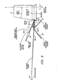
- FIG 1 is a sectional view through the center of scan
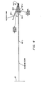
- Figure 2 which is a cross-scan view.
- Rotating polygon 12 is rotated, at a constant angular velocity, about a line denoted as center line (C/L) by a conventional drive motor arrangement (not shown).
- This polygon could have any number of facets, while for this application, the rotating polygon has 20 distinct facets.
- the polygon facets are tilted toward the center line at an angle denoted as the "draft angle" (D.A.).
- Impinging upon one facet 22 of the rotating polygon 12 is infinite conjugate light (collimated light) from a light source such as, for example, a laser 10.
- a light source such as, for example, a laser 10.
- polygon 12 is shown as having externally reflecting facets, a polygon having internally reflecting facets could be used. No optics are shown between laser 10 and facet 22 for ease of illustration, but certain optics could be necessary depending upon the type of laser chosen.
- Ray 1 coming from the laser 10 is co-planar with the center line, and is directed to facet 22 of rotating polygon 12. The light strikes the polygon and is reflected off with the angle of reflection equalling the angle of incidence.
- the angle 11 is defined in Figure 1 as the angle between laser ray 1 and the normal to the surface of facet 22.
- the normal to the facet 22 is taken to be in the plane of Figure 1, and is co-planar with the centerline and with ray 1. This position of the normal is defined as the center of scan.
- the light After the light is reflected by facet 22, it travels to first aspheric mirror surface 18.
- ray 2 is ray 1 reflected by facet 22.
- ray 1 is stationary in space regardless of the position of the polygon 12, ray 2 rotates as the polygon rotates.
- Mirror surface 18 must be large enough in the direction perpendicular to the plane of Figure 1 so that ray 2 strikes it at all times during the active scan of facet 22.
- Ray 2 is reflected from mirror surface 18, and is shown as ray 3.
- the ray 3 travels to second aspheric mirror surface 20, from which it is reflected as ray 4, as seen in Figure 1. Since ray 3 is rotating at the same angular rate as ray 2, the aspheric mirror surface 20 must be even larger than surface 18 to reflect ray 3 during active scan, because surface 20 is optically further from the facet 22 than surface 18. Ray 4 now travels back to facet 22, still with the same angular rate it had after being reflected from facet 22 as ray 2. Since the facet 22 is rotating, and ray 4 is also moving in the same direction as the facet, facet 22 need not be as large as mirror surface 20. The spacing between mirrors 18 and 20, and facet 22, must be kept small so that the mirrors and facet do not become too large. One skilled in the art of designing underfilled facet scanners will know how to choose the correct values of the laser beam parameters, so that the mirrors and the polygon do not become too large.
- Ray 4 has many angles of incidence with facet 22 during the scan, because it rotates as the polygon rotates. Only one of these angles is defined as 1 2 in Figure 1, this is the angle between ray 4 and the normal to facet 22 in the plane of the paper as shown in Figure 1. After reflection again by facet 22, ray 4 becomes ray 5, which is the photosensitive surface scanning ray that is corrected for facet-to-facet wobble, and at the same time has no bow, and is virtually free of astigmatism.
- each aspheric mirror surface be located at a stationary part of the beam.
- this point can be the point of first reflection from the facet 22, since the beam is stationary in space until after the first reflection.
- the first aspheric surface mirror 18 will form an image of the first reflection, this image is also stationary in space since the mirror 18 is stationary. This image is the other 'focus' of the first mirror 18, and is the focus of the second aspheric surface mirror 20.
- the aspheric surface mirror optics must meet the demand of reduced astigmatism and other demands, such as wobble correction, operation as "infinite conjugates", and the geometry of returning the beam after the first facet reflection, back to the facet for the second reflection at the correct angle of incidence. It is also desirable to have the first and second facet reflections occur at the same point on the facet at the center-of-scan, this minimizes the deleterious effect of facet curvature, if the facets are not manufactured to be exactly flat.
- the angles i o are the angles of incidence at the fixed, aspheric surface mirrors, the subscript 1 and 2 identify mirrors 18 and 20, respectively.
- the curvatures C x are the curvatures of the aspheric surface mirrors in the cross-scan plane, again the numerical subscripts in equations (2) and (3) identify the mirror.
- the parameters of each aspheric surface mirror can be established. These are taken as the radius of curvature at the apex of the mirror, r, and the eccentricity of the mirror, e. As before, numeric subscripts 1 and 2 are used to identify aspheric surface mirror 18 and 20, respectively.
- the mirror parameters are: where tg is an intermediate parameter given by Eccentricity is used here instead of the k parameter of equation (1), because e is signed, which is lost in squaring. The "focus" that is closer to the mirror at the point of reflection is positive, the "focus" that is further away is negative.
- the angle of incidence i oz at the second mirror 20 is 54.40788°, the value of to is 45.339685 mm, and of t, is 30.247894 mm.
- the design given above has bow, the ends of the scan are 4.572 mm lower than the center of scan. This can be greatly reduced by simply changing the three design parameters of the system such as by changing the alpha angles on surfaces 2, 11 and 27.
- the alpha angle is the angle of rotation about the X axis of the local coordinate system for a given surface.
- Equations (2) and (3) show the values of the conic mirror curvatures required in the cross-scan plane, at the center-of-scan position, at the point where the beam is reflected from each mirror. It is seen that C x1 must always be negative, because the equation for C x1 has a minus sign before it, and all the parameters in the equation are positive. This negative mirror makes it impossible to get enough Petzval curvature to cancel the scanning field curvature.
- Equations (2) and (3) were derived to satisfy two requirements-wobble correction and infinite conjugates.
- Wobble correction must be retained, therefore the requirement for inifinite conjugates would be abandoned if scanning field curvature is to be eliminated or significantly reduced.
- This means that the beam (ray 1) is not collimated at the first reflection from the facet 22.
- the deviation from collimation is not large, being 10 or 20 minutes of arc, and can be provided by standard collection optics placed between laser 10 and polygon 12.
- Equation (10) and equations (5) through (9) are used to determine the configuration of two optical power aspheric mirrors 18 and 20 which will produce a wobble corrected scan line, while ensuring that the second reflection will be superimposed on the first reflection, at the center of scan. Since the condition of infinite conjugates is no longer applicable, the position of the object point ahead of the first facet reflection must be known. This value, t 5 , is given by the equation:
- an exemplary finite conjugate diffraction limited scanner design is obtainable for 12 spots per mm.
- the pyramid polygon has 16 facets, with an active scan length of 255.54 mm.
- the duty cycle of this scan length is 79%.
- the scan is not linear, the spot velocity is that of a beam rotating at a constant angular rate, writing on a flat surface 208.28988 mm from the pivot point of the beam, through angles from zero (center of scan) to 31.5312 degrees (end of scan).
- the spot is a perfect diffraction limited spot.
- the ray error is no more than about one-twentieth of a wavelength of infrared light (800 n.m.).
- ray errors are very small, better than one-fiftieth of a wavelength.
- blue light (435.8 n.m.) the geometric aberrations do not change since the system consists only of mirrors, but these aberrations as a fraction of wavelength do change.
- the overriding effect of changing wavelength is that for blue light the f/number is much larger, to obtain 12 spots per mm. Reducing the aperture to increase the f/number eliminates the rays which cause most of the aberrations. As a result, ray errors to blue light are less than one-fortieth of a wavelength at 12 spots per mm. If the aperture is not reduced, the system will operate at 24 spots per mm to blue light. At this high resolution, the ray errors are less than one-tenth wavelength, at the end of scan. Ray errors are less than one-sixteenth of the blue wavelength over most of the scan.
- a collimated beam such as from laser 10 of Figure 1, can be used, with that beam being decollimated by conventional collection optics 50, as shown in Figure 3 to provide ray 1.
- the collection optics is some optical means of gathering the output beam from some source, such as a diode laser, a helium-neon laser, a modulator, or an incandescent lamp, and changing it to the proper size and divergence angle for the scanning system.
- the collection optics could be a specifically designed microscope objective, or a glass lens of the correct focal length with a plastic aspheric surface, such as made by Phillips of Eindhoven, The Netherlands.
- the polygon 12 has a draft angle of 8.3 degrees, and the beam is incident on the facet at an angle of 15 degrees to the facet normal.
- the beam is reflected to the first mirror 18.
- This mirror is shown symmetrical about its own axis, but only a small portion is used during the scan, as shown in Figure 4.
- the beam is reflected from the first mirror 18 to the second mirror 20.
- This mirror is also shown symmetrical about its own axis, but again only a small portion is used.
- the beam is reflected back to the facet 22. At the center of scan the beam strikes the facet the second time at the same place it was reflected the first time. After reflection from the facet the second time, the beam, desirably would pass between the two conicoidal mirrors, and is focused at the photoreceptor 24.
- the reference plane for this view is the plane of the incoming beam, this plane is normal to the paper in Figure 4. All components seen in Figure 5 are seen as projected onto this plane.
- the polygon radius is 78.1 mm in Figure 4, in Figure 5 it is the projection of 38.1 mm onto the reference plane. Since the plane of the polygon rotation is at an angle of 15+8.3 degrees to the reference plane, the radius of the polygon as seen in Figure 5 is 38.1xcos (23.3) or 35.0012 mm.
- the mirrors are shown as a section through their own axes, projected onto the reference plane.
- the actual points of reflection are not on these sections through their axes.
- the system has been adjusted so that the second reflection remains on the facet as long as the edge of the facet has not begun to move through the beam at the first reflection.
- This adjustment has the effect that each reflection is the same distance from the center of scan position.
- the beam begins to walk off the other edge of the facet at the second reflection. This adjustment is made by reducing the polygon radius.
- positions 6 and 22 correspond to facet 22 at the first and second reflections, respectively, and surfaces 13, 15 and 29 correspond respectively to mirror 18, mirror 20 and surface 24.
- Positions 1 through 5 of the Zoom Data of Tables I and II represent various angular positions of facet 22, and position 6 of the Zoom Data of Tables I and II give the changes that occur in the respective systems at position 5 with 3 arc-minutes of wobble.
Landscapes
- Physics & Mathematics (AREA)
- General Physics & Mathematics (AREA)
- Optics & Photonics (AREA)
- Mechanical Optical Scanning Systems (AREA)
- Facsimile Scanning Arrangements (AREA)
Claims (5)


Applications Claiming Priority (2)
| Application Number | Priority Date | Filing Date | Title |
|---|---|---|---|
| US06/646,324 US4682842A (en) | 1984-08-31 | 1984-08-31 | Scanning system with two reflections from scanning surface by mirrors with optical power |
| US646324 | 1984-08-31 |
Publications (2)
| Publication Number | Publication Date |
|---|---|
| EP0177174A1 EP0177174A1 (de) | 1986-04-09 |
| EP0177174B1 true EP0177174B1 (de) | 1989-05-31 |
Family
ID=24592616
Family Applications (1)
| Application Number | Title | Priority Date | Filing Date |
|---|---|---|---|
| EP85306173A Expired EP0177174B1 (de) | 1984-08-31 | 1985-08-30 | Abtastvorrichtung, wobei jede Fläche des rotierenden Polygons eine doppelte Reflexion aufweist |
Country Status (4)
| Country | Link |
|---|---|
| US (1) | US4682842A (de) |
| EP (1) | EP0177174B1 (de) |
| JP (1) | JPH077151B2 (de) |
| DE (1) | DE3570766D1 (de) |
Families Citing this family (21)
| Publication number | Priority date | Publication date | Assignee | Title |
|---|---|---|---|---|
| JPS617818A (ja) * | 1984-06-22 | 1986-01-14 | Fuji Photo Film Co Ltd | 光走査装置 |
| US4793672A (en) * | 1987-04-08 | 1988-12-27 | Compugraphic Corporation | Constant deviation scanning apparatus |
| US4805974A (en) * | 1987-11-02 | 1989-02-21 | Xerox Corporation | Polycone™ scanning system with multiple beams |
| US4797549A (en) * | 1987-11-09 | 1989-01-10 | General Motors Corporation | Optical sensor and method of making same |
| US5148285A (en) * | 1988-12-21 | 1992-09-15 | Sony Corporation | Image display apparatus with increased raster scan rate of laser beams |
| US5196957A (en) * | 1990-03-20 | 1993-03-23 | Olive Tree Technology, Inc. | Laser scanner with post-facet lens system |
| US5247383A (en) * | 1990-03-20 | 1993-09-21 | Olive Tree Technology, Inc. | Scanner with a post facet lens system |
| US5117243A (en) * | 1990-04-06 | 1992-05-26 | S&R Tech Development, Inc. | Scanner with electronic non-linearity compensation and method of processing image data |
| US5063292A (en) * | 1990-04-27 | 1991-11-05 | Xerox Corporation | Optical scanner with reduced end of scan wobble having an even number of beam reflections |
| US5136415A (en) * | 1990-07-31 | 1992-08-04 | Xerox Corporation | Multi-reflection scanner |
| US5153644A (en) * | 1991-08-19 | 1992-10-06 | Xerox Corporation | Dual mode correction of image distortion in a xerographic printing apparatus |
| US5392149A (en) * | 1992-10-20 | 1995-02-21 | E-Systems, Inc. | Polygonal mirror optical scanning system |
| US5585632A (en) * | 1995-02-28 | 1996-12-17 | University Of Washington | Wide-angle infrared cloud imager |
| US5650869A (en) * | 1995-05-05 | 1997-07-22 | The United States Of America As Represented By The Administrator Of The National Aeronautics And Space Administration | Point relay scanner utilizing ellipsoidal mirrors |
| KR100484199B1 (ko) * | 2003-03-26 | 2005-04-20 | 삼성전자주식회사 | 광주사 장치 |
| US20070294094A1 (en) * | 2006-06-20 | 2007-12-20 | Ometric Corporation | Methods of customizing, licensing and sustaining a technology option to meet a customer requirement |
| JP6121911B2 (ja) * | 2011-01-20 | 2017-04-26 | ジーイー・ヘルスケア・バイオサイエンス・コーポレイション | 光走査システム |
| EP2681607B1 (de) | 2011-03-01 | 2015-11-04 | GE Healthcare Bio-Sciences Corp. | Laserstrahlselektoren |
| DE102012111098B4 (de) | 2012-11-19 | 2016-03-03 | Scanlab Ag | Divergenzänderungsvorrichtung |
| US20170225393A1 (en) * | 2016-02-04 | 2017-08-10 | Global Filtration Systems, A Dba Of Gulf Filtration Systems Inc. | Apparatus and method for forming three-dimensional objects using two-photon absorption linear solidification |
| DE102017127420A1 (de) * | 2017-11-21 | 2019-05-23 | Sick Ag | Polygonscanner und Verfahren zum Erfassen von Objekten in einem Überwachungsbereich |
Family Cites Families (16)
| Publication number | Priority date | Publication date | Assignee | Title |
|---|---|---|---|---|
| US3520586A (en) * | 1966-06-20 | 1970-07-14 | Ampex | Entrant beam optical scanner |
| DE2306185A1 (de) * | 1973-02-08 | 1974-08-15 | Agfa Gevaert Ag | Verfahren und vorrichtung zur kompensation des pyramidenfehlers eines spiegelrades |
| US3909105A (en) * | 1974-06-17 | 1975-09-30 | Te Company | Optical image scanner with beam stabilization |
| GB1541214A (en) * | 1974-12-11 | 1979-02-28 | Atomic Energy Authority Uk | Optical apparatus |
| US4002830A (en) * | 1975-01-22 | 1977-01-11 | Laser Graphic Systems Corporation | Apparatus for compensating for optical error in a rotative mirror |
| JPS5820403B2 (ja) * | 1975-01-31 | 1983-04-22 | 富士写真フイルム株式会社 | カイテンタメンキヨウノ ヘイコウドノ ゴサオ ジヨキヨスルホウホウ |
| JPS524109A (en) * | 1975-06-27 | 1977-01-13 | Fujitsu Ltd | Scanning light distortion compensator |
| GB1567320A (en) * | 1977-01-07 | 1980-05-14 | Rank Organisation Ltd | Scanners |
| US4312590A (en) * | 1977-06-10 | 1982-01-26 | Eocom Corporation | Optical scanner and system for laser beam exposure of photo surfaces |
| JPS54123040A (en) * | 1978-03-17 | 1979-09-25 | Nippon Telegr & Teleph Corp <Ntt> | Optical beam scanning method and recorder |
| US4213157A (en) * | 1979-02-05 | 1980-07-15 | Xerox Corporation | Self tracking laser scanning apparatus |
| US4247160A (en) * | 1979-03-26 | 1981-01-27 | Xerox Corporation | Scanner with reflective pyramid error compensation |
| GB2053505A (en) * | 1979-07-10 | 1981-02-04 | Plessey Co Ltd | Scanning Beam Deflection Amplifier |
| US4268110A (en) * | 1979-10-12 | 1981-05-19 | Itek Corporation | Facet angle corrector for multi-faceted optical scanner |
| GB2115174B (en) * | 1981-11-25 | 1985-05-01 | Barr & Stroud Ltd | Optical scanning systems |
| CA1284046C (en) * | 1983-09-15 | 1991-05-14 | Harry P. Brueggemann | Wobble correction by two reflections on a facet without bow |
-
1984
- 1984-08-31 US US06/646,324 patent/US4682842A/en not_active Expired - Lifetime
-
1985
- 1985-08-20 JP JP60182875A patent/JPH077151B2/ja not_active Expired - Lifetime
- 1985-08-30 DE DE8585306173T patent/DE3570766D1/de not_active Expired
- 1985-08-30 EP EP85306173A patent/EP0177174B1/de not_active Expired
Also Published As
| Publication number | Publication date |
|---|---|
| EP0177174A1 (de) | 1986-04-09 |
| JPS6170522A (ja) | 1986-04-11 |
| US4682842A (en) | 1987-07-28 |
| JPH077151B2 (ja) | 1995-01-30 |
| DE3570766D1 (en) | 1989-07-06 |
Similar Documents
| Publication | Publication Date | Title |
|---|---|---|
| EP0177174B1 (de) | Abtastvorrichtung, wobei jede Fläche des rotierenden Polygons eine doppelte Reflexion aufweist | |
| US4624528A (en) | Scanning systems with polygon scanner having curved facets | |
| EP0311656B1 (de) | Lichtabtastvorrichtung | |
| JP3467193B2 (ja) | 屈折/反射型fθ光学素子、および走査光学系 | |
| JP3271995B2 (ja) | 光学装置 | |
| US6703634B2 (en) | 3D-shape measurement apparatus | |
| CA1284046C (en) | Wobble correction by two reflections on a facet without bow | |
| US4504110A (en) | Converging beam linear optical scanner | |
| JPH07174997A (ja) | 光走査装置 | |
| EP0658787B1 (de) | Abtastlinse und optisches Abtastsystem mit einer solchen Linse | |
| EP0176265A1 (de) | Optisches Abtastsystem | |
| US8203774B2 (en) | Optical scanning device | |
| KR920005033B1 (ko) | 포스트오브젝티브형광편향기 | |
| US5311348A (en) | Cylindrical lens system for use in laser beam scanning apparatus and scanning apparatus including same | |
| US20250147304A1 (en) | Optical scanning system | |
| JP2743176B2 (ja) | 光走査装置 | |
| JP3558837B2 (ja) | 走査結像光学系および光走査装置 | |
| JPH112769A (ja) | 光走査装置 | |
| JP3341121B2 (ja) | 走査光学系 | |
| KR100558328B1 (ko) | 광주사장치 | |
| JP2017116701A (ja) | 走査光学系及び走査レンズ | |
| JPH0235410A (ja) | 光走査装置 | |
| JP2602716B2 (ja) | 光ビーム走査用光学系 | |
| JPH0634900A (ja) | 走査光学系 | |
| JP3680921B2 (ja) | 光走査装置 |
Legal Events
| Date | Code | Title | Description |
|---|---|---|---|
| PUAI | Public reference made under article 153(3) epc to a published international application that has entered the european phase |
Free format text: ORIGINAL CODE: 0009012 |
|
| AK | Designated contracting states |
Kind code of ref document: A1 Designated state(s): DE FR GB IT |
|
| 17P | Request for examination filed |
Effective date: 19860927 |
|
| 17Q | First examination report despatched |
Effective date: 19870828 |
|
| GRAA | (expected) grant |
Free format text: ORIGINAL CODE: 0009210 |
|
| AK | Designated contracting states |
Kind code of ref document: B1 Designated state(s): DE FR GB IT |
|
| REF | Corresponds to: |
Ref document number: 3570766 Country of ref document: DE Date of ref document: 19890706 |
|
| ET | Fr: translation filed | ||
| ITF | It: translation for a ep patent filed | ||
| PLBE | No opposition filed within time limit |
Free format text: ORIGINAL CODE: 0009261 |
|
| STAA | Information on the status of an ep patent application or granted ep patent |
Free format text: STATUS: NO OPPOSITION FILED WITHIN TIME LIMIT |
|
| 26N | No opposition filed | ||
| ITTA | It: last paid annual fee | ||
| PGFP | Annual fee paid to national office [announced via postgrant information from national office to epo] |
Ref country code: FR Payment date: 20000811 Year of fee payment: 16 |
|
| PGFP | Annual fee paid to national office [announced via postgrant information from national office to epo] |
Ref country code: DE Payment date: 20000822 Year of fee payment: 16 |
|
| PGFP | Annual fee paid to national office [announced via postgrant information from national office to epo] |
Ref country code: GB Payment date: 20000830 Year of fee payment: 16 |
|
| PG25 | Lapsed in a contracting state [announced via postgrant information from national office to epo] |
Ref country code: GB Free format text: LAPSE BECAUSE OF NON-PAYMENT OF DUE FEES Effective date: 20010830 |
|
| PG25 | Lapsed in a contracting state [announced via postgrant information from national office to epo] |
Ref country code: FR Free format text: LAPSE BECAUSE OF NON-PAYMENT OF DUE FEES Effective date: 20020430 |
|
| PG25 | Lapsed in a contracting state [announced via postgrant information from national office to epo] |
Ref country code: DE Free format text: LAPSE BECAUSE OF NON-PAYMENT OF DUE FEES Effective date: 20020501 |
|
| REG | Reference to a national code |
Ref country code: FR Ref legal event code: ST |