EP0176265A1 - Optisches Abtastsystem - Google Patents
Optisches Abtastsystem Download PDFInfo
- Publication number
- EP0176265A1 EP0176265A1 EP85306174A EP85306174A EP0176265A1 EP 0176265 A1 EP0176265 A1 EP 0176265A1 EP 85306174 A EP85306174 A EP 85306174A EP 85306174 A EP85306174 A EP 85306174A EP 0176265 A1 EP0176265 A1 EP 0176265A1
- Authority
- EP
- European Patent Office
- Prior art keywords
- mirror
- facet
- scan
- mirrors
- ray
- Prior art date
- Legal status (The legal status is an assumption and is not a legal conclusion. Google has not performed a legal analysis and makes no representation as to the accuracy of the status listed.)
- Withdrawn
Links
- 230000003287 optical effect Effects 0.000 claims abstract description 16
- 201000009310 astigmatism Diseases 0.000 description 9
- 230000004075 alteration Effects 0.000 description 5
- 230000000694 effects Effects 0.000 description 5
- 206010010071 Coma Diseases 0.000 description 2
- 230000001419 dependent effect Effects 0.000 description 2
- 108091008695 photoreceptors Proteins 0.000 description 2
- 238000004088 simulation Methods 0.000 description 2
- 230000002939 deleterious effect Effects 0.000 description 1
- 238000006073 displacement reaction Methods 0.000 description 1
- 239000011521 glass Substances 0.000 description 1
- CPBQJMYROZQQJC-UHFFFAOYSA-N helium neon Chemical compound [He].[Ne] CPBQJMYROZQQJC-UHFFFAOYSA-N 0.000 description 1
- 230000001788 irregular Effects 0.000 description 1
- 230000000717 retained effect Effects 0.000 description 1
Images

Classifications
-
- G—PHYSICS
- G02—OPTICS
- G02B—OPTICAL ELEMENTS, SYSTEMS OR APPARATUS
- G02B27/00—Optical systems or apparatus not provided for by any of the groups G02B1/00 - G02B26/00, G02B30/00
- G02B27/0025—Optical systems or apparatus not provided for by any of the groups G02B1/00 - G02B26/00, G02B30/00 for optical correction, e.g. distorsion, aberration
- G02B27/0031—Optical systems or apparatus not provided for by any of the groups G02B1/00 - G02B26/00, G02B30/00 for optical correction, e.g. distorsion, aberration for scanning purposes
-
- G—PHYSICS
- G02—OPTICS
- G02B—OPTICAL ELEMENTS, SYSTEMS OR APPARATUS
- G02B13/00—Optical objectives specially designed for the purposes specified below
- G02B13/0005—Optical objectives specially designed for the purposes specified below having F-Theta characteristic
-
- G—PHYSICS
- G02—OPTICS
- G02B—OPTICAL ELEMENTS, SYSTEMS OR APPARATUS
- G02B26/00—Optical devices or arrangements for the control of light using movable or deformable optical elements
- G02B26/08—Optical devices or arrangements for the control of light using movable or deformable optical elements for controlling the direction of light
- G02B26/10—Scanning systems
Definitions
- raster scanning optical image systems utilize a rotary prismatic scanner, which by the rotational movement thereof causes the reflected light of an incident, collimated light beam to revolve about an axis near the center of rotation of the prism.
- Such scanning systems often suffer from the effects of wobble, introduced into the system by Inaccuracies in the bearings supporting the prism, and inaccuracies in the grinding and positioning of the actual facets on the faces of the prism.
- the wobble effects cause an uneven raster scan, which produces irregular locations of the output scan lines whether utilized in an input or output fashion.
- the present invention provides a scanner using a rotary prism which is as claimed in the appended claims.
- the function of the f-0 scan lens optics be provided by putting optical power on the flat mirrors that provide for the second reflection from the same facet of the draft angle polygon (prism).
- the wobble correction would still be maintained and bow would be corrected by the three design variables previously mentioned.
- anyone experienced in designing a scanner could easily make the small adjustments to the variables to obtain a bow-free scan line.
- development of this concept by arbitrarily putting spherical curvature on the flat mirrors, quickly reveals a problem: severe astigmatism. This is because of the fact that the fixed mirrors are at an angle to the beam being reflected.
- the power of a curved mirror is different in orthogonal directions when the beam is at an angle to the mirror, instead of being at near-normal angles of incidence.
- Astigmatism can be virtually eliminated by utilizing, instead of flat mirrors, mirrors with optical power, that is, mirrors with curved active surfaces that are rotationally symmetric but not spherical, that is, aspheric surfaces which have the form: where, in rectangular coordinates
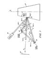
- FIG 1 is a sectional view through the center of scan
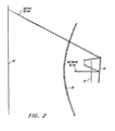
- Figure 2 which is a cross-scan view.
- Rotating polygon 12 is rotated, at a constant angular speed, about a line denoted as center line (C/L) by a conventional drive motor arrangement (not shown).
- This polygon could have any number of facets, while for this application, the rotating polygon has 20 distinct facets.
- the polygon facets are tilted toward the center line at an angle denoted as the "draft angle" (D.A.).
- Impinging upon one facet 22 of the rotating polygon 12 is infinite conjugate light (collimated light) from a light source such as, for example, a laser 10.
- a light source such as, for example, a laser 10.
- polygon 12 is shown as having externally reflecting facets, a polygon having internally reflecting facets could be used. No optics are shown between laser 10 and facet 22 for ease of illustration, but certain optics could be necessary depending upon the type of laser chosen.
- Ray 1 coming from the laser 10 is coplanar with the center line, and is directed to facet 22 of rotating polygon 12. The light strikes the polygon and is reflected, with the angle of reflection equalling the angle of incidence.
- the angle 11 is defined in Figure 1 as the angle between laser ray 1 and the normal to the surface of facet 22.
- the normal to the facet 22 is taken to be in the plane of Figure 1, and is coplanar with the centerline and with ray 1. This position of the normal is defined as the center of scan.
- This position of the normal is defined as the center of scan.
- ray 2 is ray 1 reflected by facet 22.
- ray 1 is stationary in space regardless of the position of the polygon 12, ray 2 rotates as the polygon rotates.
- Mirror surface 18 must be large enough in the direction perpendicular to the plane of Figure 1 so that ray 2 strikes it at all times during the active scan of facet 22.
- Ray 2 is reflected from mirror surface 18, and is shown as ray 3.
- the ray 3 travels to second aspheric mirror surface 20, from which it Is reflected as ray 4, as seen in Figure 1. Since ray 3 is rotating at the same angular rate as ray 2, the aspheric mirror surface 20 must be even larger than surface 18 to reflect ray 3 during active scan, because surface 20 is optically further from the facet 22 than surface 18. Ray 4 now travels back to facet 22, still with the same angular rate it had after being reflected from facet 22 as ray 2. Since the facet 22 is rotating, and ray 4 is also moving in the same direction as the facet, facet 22 need not be as large as mirror surface 20. The spacing between mirrors 18 and 20, and facet 22, must be kept small so that the mirrors and facet do not become too large. One skilled in the art of designing underfilled facet scanners will know how to choose the correct values of the laser beam parameters, so that the mirrors and the poygon do not become too large.
- Ray 4 has many angles of incidence with facet 22 during the scan, because it rotates as the polygon rotates. Only one of these angles is defined as I 2 in Figure 1, this is the angle between ray 4 and the normal to facet 22 in the plane of the paper as shown in Figure 1. After reflection again by facet 22, ray 4 becomes ray 5, which is the photosensitive surface scanning ray that is corrected for facet-to-facet wobble, and at the same time has no bow, and is virtually free of astigmatism.
- each aspheric mirror surface be located at a stationary part of the beam.
- this point can be the point of first reflection from the facet 22, since the beam is stationary in space until after the first reflection.
- the first aspheric surface mirror 18 will form an image of the first reflection, this image is also stationary in space since the mirror 18 is stationary. This image is the other 'focus' of the first mirror 18, and is the focus of the second aspheric surface mirror 20.
- the aspheric surface mirror optics must meet the demand of reduced astigmatism and other demands, such as wobble correction, operation at "infinite conjugates", and the geometry of returning the beam after the first facet reflection, back to the facet for the second reflection at the correct angle of incidence. It is also desirable to have the first and second facet reflections occur at the same point on the facet at the center-of-scan, this minimizes the deleterious effect of facet curvature, if the facets are not manufactured to be exactly flat.
- the angles i o are the angles of incidence at the fixed, aspheric surface mirrors, the subscript 1 and 2 identify mirrors 18 and 20, respectively.
- the curvatures C x are the curvatures of the aspheric surface mirrors in the cross-scan plane, again the numerical subscripts in equations (2) and (3) identify the mirror.
- the mirror parameters are: where t 9 is an intermediate parameter given by Eccentricity is used here instead of the k parameter of equation (1), because e is signed, which is lost in squaring.
- t 9 is an intermediate parameter given by Eccentricity is used here instead of the k parameter of equation (1), because e is signed, which is lost in squaring.
- the "focus” that is closer to the mirror at the point of reflection is positive, the "focus” that is further away is negative.
- the angle of incidence 1 02 at the second mirror 20 is 54.40788°, the value of to is 1.785027 Inches, and of t l is 1.190862 inches.
- the design given above has bow, the ends of the scan being 4.57 mm lower than the center of scan. This can be greatly reduced by simply changing the three design parameters of the system such as by changing the alpha angles on surfaces 2, 11 and 27.
- Equations (2) and (3) show the values of the conic mirror curvatures required in the cross-scan plane, at the center-of-scan position, at the point where the beam is reflected from each mirror. It is seen that C xl must always be negative, because the equation for C xl has a minus sign before it, and all the parameters in the equation are positive. This negative mirror makes it impossible to get enough Petzval curvature to cancel the scanning field curvature.
- Equations (2) and (3) were derived to satisfy two requirements - wobble correction and infinite conjugates.
- Wobble correction must be retained, therefore the requirement for infinite conjugates would be abandoned if scanning field curvature is to be eliminated or significantly reduced.
- This means that the beam (ray 1) is not collimated at the first reflection from the facet 22.
- the deviation from collimation is not large, being 10 or 20 minutes of arc, and can be provided by standard collection optics placed between laser 10 and polygon 12.
- Equation (10) and equations (5) through (9) are used to determine the configuration of two optical power aspheric mirrors 18 and 20 which will produce a wobble-corrected scan line, while ensuring that the second reflection will be superimposed on the first reflection, at the center of scan. Since the condition of infinite conjugates is no longer applicable, the position of the object point ahead of the first facet reflection must be known. This value, t 5 , is given by the equation:
- an exemplary finite conjugate diffraction limited scanner design is obtainable for 12 spots per mm.
- the pyramid polygon has 16 facets, with an active scan length of 255.52 mm.
- the duty cycle of this scan length is 79%.
- the scan is not linear, the spot velocity is that of a beam rotating at a constant angular rate, writing on a flat surface 8.200389 inches from the pivot point of the beam, through angles from zero (center of scan) to 31.5312 degrees (end of scan).
- the accuracy of this simulation is better than one millionth of a mm.
- the spot is a perfect diffraction-limited spot.
- the ray error is no more than about one-twentieth of a wavelength of infrared light (800 nm).
- ray errors are very small, better than one- fiftieth of a wavelength.
- blue light (435.8 nm) the geometric aberrations do not change since the system consists only of mirrors, but these aberrations as a fraction of wavelength do change.
- the overriding effect of changing wavelength is that for blue light the f/number is much larger, to obtain 12 spots per mm. Reducing the aperture to increase the f/number eliminates the rays which cause most of the aberrations. As a result, ray errors to blue light are less than one- fortieth of a wavelength at 12 spots per mm. If the aperture is not reduced, the system will operate at 24 spots per mm to blue light. At this high resolution, the ray errors are less than one-tenth wavelength, at the end of scan. Ray errors are less than one-sixteenth of the blue wavelength over most of the scan.
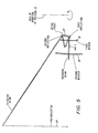
- a collimated beam such as from laser 10 of Figure 1, can be used, with that beam being decollimated by conventional collection optics 50, as shown in Figure 3 to provide ray 1.
- the collection optics is some optical means of gathering the output beam from some source, such as a diode laser, a helium-neon laser, a modulator, or an incandescent lamp, and changing it to the proper size and divergence angle for the scanning system.
- the collection optics could be a specifically designed microscope objective, or a glass lens of the correct focal length with a plastic aspheric surface, such as made by Philips of Eindhoven, The Netherlands.
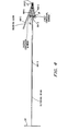
- the polygon 18 has a draft angle of 8.3 degrees, and the beam is incident on the facet at an angle of 15 degrees to the facet normal.
- the beam is reflected to the first mirror 18.
- This mirror is shown symmetrical about its own axis, but only a small portion is used during the scan, as shown in Figure 4.
- the beam is reflected from the first mirror 18 to the second mirror 20.
- This mirror is also shown symmetrical about its own axis, but again only a small portion is used.
- the beam is reflected back to the facet 22. At the center of scan the beam strikes the facet the second time at the same place it was reflected the first time. After reflection from the facet the second time, the beam would pass between the two conicoidal mirrors, and is focused at the photoreceptor 24.
- the reference plane for this view is the plane of the incoming beam, this plane is normal to the paper in Figure 4. All components seen in Figure 5 are seen as projected onto this plane.
- the polygon radius is 38 mm in Figure 4, in Figure 5 it is the projection of 38 mm onto the reference plane. Since the plane of the polygon rotation is at an angle of 15 + 8.3 degrees to the reference plane, the radius of the polygon as seen in Figure 5 is 1.5 x cos (23.3) or 35 mm.
- the mirrors are shown as a section through their own axes, projected onto the reference plane.
- the actual points of reflection are not on these sections through their axes.
- the system has been adjusted so that the second reflection remains on the facet as long as the edge of the facet has not begun to move through the beam at the first reflection.
- This adjustment has the effect that each reflection is the same distance from the center-of-scan position.
- the beam begins to walk off the other edge of the facet at the second reflection. This adjustment is made by reducing the polygon radius.
- positions 6 and 22 correspond to facet 22 at the first and second reflections, respectively, and surfaces 13, 15, and 29 correspond respectively to mirror 18, mirror 20 and surface 24.
- Positions 1 through 5 of the Zoom Data of Tables I and II represent various angular positions of facet 22, and position 6 of the Zoom Data of Tables I and II gives the changes that occur in the respective systems at position 5 with 3 arc-minutes of wobble.
Landscapes
- Physics & Mathematics (AREA)
- General Physics & Mathematics (AREA)
- Optics & Photonics (AREA)
- Mechanical Optical Scanning Systems (AREA)
- Lenses (AREA)
- Facsimile Scanning Arrangements (AREA)
Applications Claiming Priority (2)
| Application Number | Priority Date | Filing Date | Title |
|---|---|---|---|
| US64728184A | 1984-09-04 | 1984-09-04 | |
| US647281 | 1984-09-04 |
Publications (1)
| Publication Number | Publication Date |
|---|---|
| EP0176265A1 true EP0176265A1 (de) | 1986-04-02 |
Family
ID=24596332
Family Applications (1)
| Application Number | Title | Priority Date | Filing Date |
|---|---|---|---|
| EP85306174A Withdrawn EP0176265A1 (de) | 1984-09-04 | 1985-08-30 | Optisches Abtastsystem |
Country Status (2)
| Country | Link |
|---|---|
| EP (1) | EP0176265A1 (de) |
| JP (1) | JPS6170523A (de) |
Cited By (1)
| Publication number | Priority date | Publication date | Assignee | Title |
|---|---|---|---|---|
| CN109283540A (zh) * | 2018-09-30 | 2019-01-29 | 江苏慧光电子科技有限公司 | 适用于输出图案化光束的系统和光路结构 |
Citations (5)
| Publication number | Priority date | Publication date | Assignee | Title |
|---|---|---|---|---|
| US3897132A (en) * | 1973-02-08 | 1975-07-29 | Agfa Gevaert Ag | Method and apparatus for correcting pyramidal error in an optical system with a mirror wheel |
| GB1541214A (en) * | 1974-12-11 | 1979-02-28 | Atomic Energy Authority Uk | Optical apparatus |
| EP0014548A2 (de) * | 1979-02-05 | 1980-08-20 | Xerox Corporation | Lichtpunktabtaster |
| FR2517078A1 (fr) * | 1981-11-25 | 1983-05-27 | Barr & Stroud Ltd | Systeme de balayage optique |
| EP0138400A1 (de) * | 1983-09-15 | 1985-04-24 | Xerox Corporation | Optisches Gerät mit einer Abtastpolygonspiegelanordnung |
-
1985
- 1985-08-20 JP JP60182876A patent/JPS6170523A/ja active Pending
- 1985-08-30 EP EP85306174A patent/EP0176265A1/de not_active Withdrawn
Patent Citations (5)
| Publication number | Priority date | Publication date | Assignee | Title |
|---|---|---|---|---|
| US3897132A (en) * | 1973-02-08 | 1975-07-29 | Agfa Gevaert Ag | Method and apparatus for correcting pyramidal error in an optical system with a mirror wheel |
| GB1541214A (en) * | 1974-12-11 | 1979-02-28 | Atomic Energy Authority Uk | Optical apparatus |
| EP0014548A2 (de) * | 1979-02-05 | 1980-08-20 | Xerox Corporation | Lichtpunktabtaster |
| FR2517078A1 (fr) * | 1981-11-25 | 1983-05-27 | Barr & Stroud Ltd | Systeme de balayage optique |
| EP0138400A1 (de) * | 1983-09-15 | 1985-04-24 | Xerox Corporation | Optisches Gerät mit einer Abtastpolygonspiegelanordnung |
Non-Patent Citations (2)
| Title |
|---|
| PATENTS ABSTRACTS OF JAPAN, vol. 8, no. 219 (P-306)[1656], 5th October 1984; & JP-A-59 102 211 (DERUFUAI K.K.) 13-06-1984 * |
| PATENTS ABSTRACTS OF JAPAN, vol. 8, no. 237 (P-310)[1674], 30th October 1984; & JP-A-59 113 409 (KOPARU EREKUTORA K.K.) 30-06-1984 * |
Cited By (1)
| Publication number | Priority date | Publication date | Assignee | Title |
|---|---|---|---|---|
| CN109283540A (zh) * | 2018-09-30 | 2019-01-29 | 江苏慧光电子科技有限公司 | 适用于输出图案化光束的系统和光路结构 |
Also Published As
| Publication number | Publication date |
|---|---|
| JPS6170523A (ja) | 1986-04-11 |
Similar Documents
| Publication | Publication Date | Title |
|---|---|---|
| EP0177174B1 (de) | Abtastvorrichtung, wobei jede Fläche des rotierenden Polygons eine doppelte Reflexion aufweist | |
| US4624528A (en) | Scanning systems with polygon scanner having curved facets | |
| US4277128A (en) | Anamorphic Fθ lens system | |
| US5168386A (en) | Flat field telecentric scanner | |
| JP2763055B2 (ja) | 実入射瞳を有する反射光学トリプレット | |
| CA1247898A (en) | Scanner optics with no cross scan field curvature | |
| EP0311656B1 (de) | Lichtabtastvorrichtung | |
| JP3467193B2 (ja) | 屈折/反射型fθ光学素子、および走査光学系 | |
| JPH06118325A (ja) | 光走査装置 | |
| JP3271995B2 (ja) | 光学装置 | |
| US6703634B2 (en) | 3D-shape measurement apparatus | |
| CA1284046C (en) | Wobble correction by two reflections on a facet without bow | |
| US4504110A (en) | Converging beam linear optical scanner | |
| EP0658787B1 (de) | Abtastlinse und optisches Abtastsystem mit einer solchen Linse | |
| KR920005033B1 (ko) | 포스트오브젝티브형광편향기 | |
| JP2743176B2 (ja) | 光走査装置 | |
| JPH1039244A (ja) | 受動的面追尾式システム及び走査システム | |
| SU1095123A1 (ru) | Оптическа система со сканируемым полем зрени | |
| US20250164777A1 (en) | Optical scanning system | |
| JPS6170523A (ja) | 多角形体式走査装置 | |
| JP3558837B2 (ja) | 走査結像光学系および光走査装置 | |
| JPH112769A (ja) | 光走査装置 | |
| JP3341121B2 (ja) | 走査光学系 | |
| JP3680921B2 (ja) | 光走査装置 | |
| JPH0235410A (ja) | 光走査装置 |
Legal Events
| Date | Code | Title | Description |
|---|---|---|---|
| PUAI | Public reference made under article 153(3) epc to a published international application that has entered the european phase |
Free format text: ORIGINAL CODE: 0009012 |
|
| AK | Designated contracting states |
Kind code of ref document: A1 Designated state(s): DE FR GB IT |
|
| 17P | Request for examination filed |
Effective date: 19860927 |
|
| 17Q | First examination report despatched |
Effective date: 19870826 |
|
| STAA | Information on the status of an ep patent application or granted ep patent |
Free format text: STATUS: THE APPLICATION HAS BEEN WITHDRAWN |
|
| 18W | Application withdrawn |
Withdrawal date: 19871111 |
|
| RIN1 | Information on inventor provided before grant (corrected) |
Inventor name: BRUEGGEMANN, HARRY P. |