EP0177214A2 - Kompakte Brennkraftmaschinen - Google Patents
Kompakte Brennkraftmaschinen Download PDFInfo
- Publication number
- EP0177214A2 EP0177214A2 EP85306612A EP85306612A EP0177214A2 EP 0177214 A2 EP0177214 A2 EP 0177214A2 EP 85306612 A EP85306612 A EP 85306612A EP 85306612 A EP85306612 A EP 85306612A EP 0177214 A2 EP0177214 A2 EP 0177214A2
- Authority
- EP
- European Patent Office
- Prior art keywords
- power
- roller
- return
- pistons
- shaft
- Prior art date
- Legal status (The legal status is an assumption and is not a legal conclusion. Google has not performed a legal analysis and makes no representation as to the accuracy of the status listed.)
- Granted
Links
Images




Classifications
-
- F—MECHANICAL ENGINEERING; LIGHTING; HEATING; WEAPONS; BLASTING
- F01—MACHINES OR ENGINES IN GENERAL; ENGINE PLANTS IN GENERAL; STEAM ENGINES
- F01B—MACHINES OR ENGINES, IN GENERAL OR OF POSITIVE-DISPLACEMENT TYPE, e.g. STEAM ENGINES
- F01B9/00—Reciprocating-piston machines or engines characterised by connections between pistons and main shafts, not specific to groups F01B1/00 - F01B7/00
- F01B9/04—Reciprocating-piston machines or engines characterised by connections between pistons and main shafts, not specific to groups F01B1/00 - F01B7/00 with rotary main shaft other than crankshaft
- F01B9/06—Reciprocating-piston machines or engines characterised by connections between pistons and main shafts, not specific to groups F01B1/00 - F01B7/00 with rotary main shaft other than crankshaft the piston motion being transmitted by curved surfaces
-
- F—MECHANICAL ENGINEERING; LIGHTING; HEATING; WEAPONS; BLASTING
- F02—COMBUSTION ENGINES; HOT-GAS OR COMBUSTION-PRODUCT ENGINE PLANTS
- F02B—INTERNAL-COMBUSTION PISTON ENGINES; COMBUSTION ENGINES IN GENERAL
- F02B61/00—Adaptations of engines for driving vehicles or for driving propellers; Combinations of engines with gearing
- F02B61/04—Adaptations of engines for driving vehicles or for driving propellers; Combinations of engines with gearing for driving propellers
- F02B61/045—Adaptations of engines for driving vehicles or for driving propellers; Combinations of engines with gearing for driving propellers for marine engines
-
- F—MECHANICAL ENGINEERING; LIGHTING; HEATING; WEAPONS; BLASTING
- F02—COMBUSTION ENGINES; HOT-GAS OR COMBUSTION-PRODUCT ENGINE PLANTS
- F02B—INTERNAL-COMBUSTION PISTON ENGINES; COMBUSTION ENGINES IN GENERAL
- F02B75/00—Other engines
- F02B75/16—Engines characterised by number of cylinders, e.g. single-cylinder engines
- F02B75/18—Multi-cylinder engines
- F02B75/24—Multi-cylinder engines with cylinders arranged oppositely relative to main shaft and of "flat" type
- F02B75/243—Multi-cylinder engines with cylinders arranged oppositely relative to main shaft and of "flat" type with only one crankshaft of the "boxer" type, e.g. all connecting rods attached to separate crankshaft bearings
-
- F—MECHANICAL ENGINEERING; LIGHTING; HEATING; WEAPONS; BLASTING
- F01—MACHINES OR ENGINES IN GENERAL; ENGINE PLANTS IN GENERAL; STEAM ENGINES
- F01B—MACHINES OR ENGINES, IN GENERAL OR OF POSITIVE-DISPLACEMENT TYPE, e.g. STEAM ENGINES
- F01B9/00—Reciprocating-piston machines or engines characterised by connections between pistons and main shafts, not specific to groups F01B1/00 - F01B7/00
- F01B9/04—Reciprocating-piston machines or engines characterised by connections between pistons and main shafts, not specific to groups F01B1/00 - F01B7/00 with rotary main shaft other than crankshaft
- F01B9/06—Reciprocating-piston machines or engines characterised by connections between pistons and main shafts, not specific to groups F01B1/00 - F01B7/00 with rotary main shaft other than crankshaft the piston motion being transmitted by curved surfaces
- F01B2009/061—Reciprocating-piston machines or engines characterised by connections between pistons and main shafts, not specific to groups F01B1/00 - F01B7/00 with rotary main shaft other than crankshaft the piston motion being transmitted by curved surfaces by cams
- F01B2009/065—Bi-lobe cams
-
- F—MECHANICAL ENGINEERING; LIGHTING; HEATING; WEAPONS; BLASTING
- F02—COMBUSTION ENGINES; HOT-GAS OR COMBUSTION-PRODUCT ENGINE PLANTS
- F02B—INTERNAL-COMBUSTION PISTON ENGINES; COMBUSTION ENGINES IN GENERAL
- F02B75/00—Other engines
- F02B75/16—Engines characterised by number of cylinders, e.g. single-cylinder engines
- F02B75/18—Multi-cylinder engines
- F02B2075/1804—Number of cylinders
- F02B2075/1808—Number of cylinders two
-
- F—MECHANICAL ENGINEERING; LIGHTING; HEATING; WEAPONS; BLASTING
- F02—COMBUSTION ENGINES; HOT-GAS OR COMBUSTION-PRODUCT ENGINE PLANTS
- F02B—INTERNAL-COMBUSTION PISTON ENGINES; COMBUSTION ENGINES IN GENERAL
- F02B3/00—Engines characterised by air compression and subsequent fuel addition
- F02B3/06—Engines characterised by air compression and subsequent fuel addition with compression ignition
-
- F—MECHANICAL ENGINEERING; LIGHTING; HEATING; WEAPONS; BLASTING
- F02—COMBUSTION ENGINES; HOT-GAS OR COMBUSTION-PRODUCT ENGINE PLANTS
- F02B—INTERNAL-COMBUSTION PISTON ENGINES; COMBUSTION ENGINES IN GENERAL
- F02B75/00—Other engines
- F02B75/32—Engines characterised by connections between pistons and main shafts and not specific to preceding main groups
Definitions
- This invention relates generally to internal combustion engines, and more particularly to light weight, compact engines suitable for example for powering lightweight (ultralight) aircraft, outbound motor boats, stationary power plants, automobiles, motorcycles etc.
- the engine design is capable of utilizing standard four-stroke operation in conventional or diesel applications.
- One object of the invention is to provide an improved engine having the above advantages and features of construction.
- the engine is characterised by:
- the four stroke engine may typically include a cross head slider and a lateral guide roller also carried by each of the pistons, and guide structure associated with each cylinder for guiding reciprocating movement of said slider and guide roller.
- Four piston strokes produces one revolution of the output shaft.
- the engine may typically include a mounting shaft associated with each piston, and mounting power roller, a return roller, a slider and a guide roller.
- the power roller and guide roller are located between the slider and return roller, the power roller located between the slider and the guide roller.
- the mounting shaft typically has a first section carrying the slider, power roller and guide roller, and a second section carrying the return roller, the power roller axis defined by the first section and the return roller axis defined by the second section.
- the power output shaft may typically have an I-shaped cross-section normal to the output shaft axis at a location radially inwardly of the guide roller. In this regard, the minimum thickness dimension of said I-shaped cross section is approached by the guide roller and is less than the minimum cross-sectional thickness of the power cam.
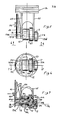
- the internal combustion engine 10 shown in the drawings includes a pair of opposed cylinders 11 and pistons 12 reciprocating in bores 11a therein.
- a power output shaft 13 rotates about axis 13a, extending generally perpendicularly to the axes of piston reciprocation.
- Shaft 13 has an integral and external cam as defined by two lobes 14 located to be driven in rotation by two power rollers 15 respectively carried by the pistons, in response to power stroke travel by the pistons toward axis 13a.
- a circular flange 16 is integral with the output shaft, and has an internal cam track 16a located to be engaged by two return rollers 17 respectively carried by the pistons, in response to travel by the pistons away from axis 13a. As shown, the return rollers fit within a cavity or recess 18 formed in the side of flange 16, for compactness. Track 16a also has two lobe shafts.
- a mounting shaft 19 is associated with each piston and mounts the associated power roller 15 and return roller 17 as shown.
- the axis 17a of rotation of return roller 17 about the shaft 19 is parallel to but offset closer to shaft axis 13a than the axis 15a of rotation of power roller 15 about shaft 19.
- This construction also enables location of piston 12 closer to shaft axis 13a. Note in Figures 7 and 8 that the surface of the power roller 15 closest to the shaft axis engages the driven cam, as at 20, and the surface of the return roller 17 furthest from the axis 13a engages the cam track 16a, at 21.
- the first section 19a of the mounting shaft also carries a radially elongated cross head slider 22 for guided travel adjacent radially extending guide surface 23a which is arcuate in cross section (see Figure 6).
- Surface 23a is defined by a radially extending guide 23 integral with the engine body or cylinder 11.
- Slider 22 is located at one end of the shaft section 19a, at the outer side of the piston strut 24.
- Return roller 17 is located at the end of shaft section 19b, at the outer side of piston strut 25.
- Struts 24 and 25 carry the mounting shaft for reciprocating travel in the direction indicated by arrows 26 in Figure 5.
- Power roller 15 and a guide roller 27 are carried between struts 24 and 25, for rotation about the shaft section 19a, as shown.
- Lateral guide roller 27 rotates independently of roller 15, and between two fixed guides 28, which extend in directions 26 and which may be integral with the cylinder 11. As a result, optimum balance is achieved. See Figure 6 showing elements 15, 17, 23 and 27 located in balanced relation.
- Figure 7 shows the fixed (as for example, pinned) attachment of the mounting shaft to the two struts, at 24a and 25a. Also, needle bearing sets 32, 33 and 34 support roller 15, 17 and 27 for rotation on the mounting shaft.
- the power output shaft is cut-away at 30 and 31, to have an I-shaped cross section of thickness d whereby the rollers 17 and 27 may approach close to axis 13a and in the cut-aways, at bottom dead centre position of the piston.
- Power rollers 15 at that time engage the power cam at locations 32 and 33, having spacing d 21 where d 2 d .
- This also facilitates compactness, since the piston may approach close to the axis 13a (see dimension d 3 ). Also bending strength is not compromised.
- passages 36-39 in mounting shaft sections 19a, 19b, and 19c feed pressurised lubricant to the needle bearings, from an oil port 40 in casing 41 (see lubricant supply duct 42).
- passage 35 in the slider momentarily registers with port 40, to receive a metered amount of lubricant.
- the engine also includes cylinder heads 50 defining combustible mixture compression chambers 51; mixture inlet ducts 52, spark plugs 53, mixture inlet valves 54 on push rods 55; springs 56 urging the rods 55 towards cam 56a on shaft 13; exhaust valves 57 on push rods 58, the latter urged by springs 59 toward cam 60 on shaft 13.
- a propeller 61 may be mounted on shaft 13, as shown.
- Figure 14 shows four cams 62 - 65 on a shaft 13, for operating inlet and exhaust push rods in the event of a staggered firing order i.e. one cam set dedicated to odd numbered cylinders.
- Cams 62 and 63 control one cylinder
- cams 64 and 65 control a second cylinder.
- Shaft bearings appear at 70 in Figures 8 and 10.
- Figure 15 is a schematic showing the cylinder arrangement about the shaft axis, for the Figure 14 engine;
- Figure 16 is like Figure 15, but showing a modified cylinder arrangement;
- Figure 17 is a view showing an eight cylinder arrangement.
Landscapes
- Engineering & Computer Science (AREA)
- Mechanical Engineering (AREA)
- General Engineering & Computer Science (AREA)
- Chemical & Material Sciences (AREA)
- Combustion & Propulsion (AREA)
- Ocean & Marine Engineering (AREA)
- Valve Device For Special Equipments (AREA)
- Transmission Devices (AREA)
- Valve-Gear Or Valve Arrangements (AREA)
- Lubrication Of Internal Combustion Engines (AREA)
Priority Applications (1)
| Application Number | Priority Date | Filing Date | Title |
|---|---|---|---|
| AT85306612T ATE43152T1 (de) | 1984-10-01 | 1985-09-17 | Kompakte brennkraftmaschinen. |
Applications Claiming Priority (2)
| Application Number | Priority Date | Filing Date | Title |
|---|---|---|---|
| US656682 | 1984-10-01 | ||
| US06/656,682 US4545336A (en) | 1984-10-01 | 1984-10-01 | Engine with roller and cam drive from piston to output shaft |
Publications (3)
| Publication Number | Publication Date |
|---|---|
| EP0177214A2 true EP0177214A2 (de) | 1986-04-09 |
| EP0177214A3 EP0177214A3 (en) | 1987-06-24 |
| EP0177214B1 EP0177214B1 (de) | 1989-05-17 |
Family
ID=24634111
Family Applications (1)
| Application Number | Title | Priority Date | Filing Date |
|---|---|---|---|
| EP85306612A Expired EP0177214B1 (de) | 1984-10-01 | 1985-09-17 | Kompakte Brennkraftmaschinen |
Country Status (5)
| Country | Link |
|---|---|
| US (1) | US4545336A (de) |
| EP (1) | EP0177214B1 (de) |
| JP (1) | JPS61160528A (de) |
| AT (1) | ATE43152T1 (de) |
| DE (1) | DE3570264D1 (de) |
Cited By (1)
| Publication number | Priority date | Publication date | Assignee | Title |
|---|---|---|---|---|
| WO1995018915A1 (en) * | 1994-01-01 | 1995-07-13 | Chen Fei Chang | An engine with reciprocating coupling pistons and with one cam for each cylinder group |
Families Citing this family (22)
| Publication number | Priority date | Publication date | Assignee | Title |
|---|---|---|---|---|
| FR2607552B1 (fr) * | 1986-05-21 | 1991-07-19 | Innovations Atel Const | Moteur a explosion sans embiellage ni vilebrequin de type cylindres en etoile |
| JPH0711241B2 (ja) * | 1988-06-28 | 1995-02-08 | スプリット・サイクル・テクノロジー・リミテッド | 星形シリンダ機械 |
| GB8926818D0 (en) * | 1989-11-28 | 1990-01-17 | Ehrlich Josef | Drive/driven apparatus |
| US5553574A (en) * | 1991-12-05 | 1996-09-10 | Advanced Automotive Technologies, Inc. | Radial cam internal combustion engine |
| US5634441A (en) * | 1996-01-16 | 1997-06-03 | W. Parker Ragain | Power transfer mechanism |
| AUPR462501A0 (en) * | 2001-04-27 | 2001-05-24 | Maslen, Des | Radial engine |
| US6691648B2 (en) * | 2001-07-25 | 2004-02-17 | Mark H. Beierle | Radial cam driven internal combustion engine |
| ITMO20010174A1 (it) * | 2001-08-28 | 2003-02-28 | Fantuzzi Reggiane Corp S A | Motore a combustione interna a funzionamento alternativo perfezionato |
| US7475627B2 (en) * | 2005-09-27 | 2009-01-13 | Ragain Air Compressors, Inc. | Rotary to reciprocal power transfer device |
| WO2008024464A2 (en) | 2006-08-23 | 2008-02-28 | Warp Drive Engines | Engine |
| DE102008002100A1 (de) * | 2008-05-23 | 2009-11-26 | Vonderlind, Manfred | Motor mit einer Kurvenscheibe |
| US8336304B2 (en) * | 2008-06-24 | 2012-12-25 | Rez Mustafa | Hydraulic hybrid turbo-transmission |
| US20090313984A1 (en) * | 2008-06-24 | 2009-12-24 | Rez Mustafa | Hydraulic hybrid turbo transmission |
| US8235150B2 (en) * | 2008-06-24 | 2012-08-07 | Rez Mustafa | Pneumatic hybrid turbo transmission |
| US8087487B2 (en) * | 2008-11-12 | 2012-01-03 | Rez Mustafa | Hybrid turbo transmission |
| US8622032B2 (en) | 2008-09-25 | 2014-01-07 | Mustafa Rez | Internal combustion engine with dual-chamber cylinder |
| US8191517B2 (en) * | 2008-09-25 | 2012-06-05 | Rez Mustafa | Internal combustion engine with dual-chamber cylinder |
| US8490584B2 (en) * | 2008-09-25 | 2013-07-23 | Rez Mustafa | Air hybrid engine with dual chamber cylinder |
| JP5480999B2 (ja) * | 2010-08-03 | 2014-04-23 | ハンビー,ダブリュ.,ダニエル | ローラ付きドウェル・サイクル・クランク |
| US9080498B2 (en) | 2012-04-11 | 2015-07-14 | Mustafa Rez | Combustion engine with a pair of one-way clutches used as a rotary shaft |
| US9382839B2 (en) * | 2014-03-25 | 2016-07-05 | Jeffrey Bonner | Combustion engine comprising a central cam-drive system |
| ITUA20161439A1 (it) * | 2016-03-08 | 2017-09-08 | Carlo Zambonardi | Motore volumetrico alternativo alimentato con un gas in pressione, in particolare aria compressa |
Family Cites Families (13)
| Publication number | Priority date | Publication date | Assignee | Title |
|---|---|---|---|---|
| GB191001892A (en) * | 1909-05-25 | 1910-05-25 | Carlo Baulino | Improvements in and relating to Internal Combustion Engines. |
| US1355451A (en) * | 1918-06-19 | 1920-10-12 | Carpenter Lee Royal | Internal-combustion engine |
| US1711260A (en) * | 1925-11-16 | 1929-04-30 | Fairchild Caminez Engine Corp | Cam construction for cam engines |
| US1648780A (en) * | 1926-11-19 | 1927-11-08 | Nuesell Gerard | Internal-combustion engine |
| US1863877A (en) * | 1928-04-02 | 1932-06-21 | Rightenour Asa Lee | Internal combustion engine |
| US1931401A (en) * | 1931-02-28 | 1933-10-17 | Bernard L Baisden | Eight cylinder radial motor |
| GB402323A (en) * | 1933-04-13 | 1933-11-30 | Emile Dasset | Improvements in and relating to radial cylinder engines |
| US2050578A (en) * | 1934-12-29 | 1936-08-11 | Morreau Henri | Engine |
| FR1375892A (fr) * | 1963-09-09 | 1964-10-23 | Moteur à combustion interne | |
| US3572209A (en) * | 1967-11-28 | 1971-03-23 | Hal F Aldridge | Radial engine |
| DE1776054A1 (de) * | 1968-09-12 | 1970-11-12 | Hatz Motoren | Kolbenmaschine |
| US3584610A (en) * | 1969-11-25 | 1971-06-15 | Kilburn I Porter | Internal combustion engine |
| US4331108A (en) * | 1976-11-18 | 1982-05-25 | Collins Brian S | Radial engine |
-
1984
- 1984-10-01 US US06/656,682 patent/US4545336A/en not_active Expired - Fee Related
-
1985
- 1985-09-17 AT AT85306612T patent/ATE43152T1/de not_active IP Right Cessation
- 1985-09-17 EP EP85306612A patent/EP0177214B1/de not_active Expired
- 1985-09-17 DE DE8585306612T patent/DE3570264D1/de not_active Expired
- 1985-10-01 JP JP60218990A patent/JPS61160528A/ja active Pending
Cited By (2)
| Publication number | Priority date | Publication date | Assignee | Title |
|---|---|---|---|---|
| WO1995018915A1 (en) * | 1994-01-01 | 1995-07-13 | Chen Fei Chang | An engine with reciprocating coupling pistons and with one cam for each cylinder group |
| US5836234A (en) * | 1994-01-01 | 1998-11-17 | Chen; Feichang | Single CAM reciprocating linked piston type engine |
Also Published As
| Publication number | Publication date |
|---|---|
| DE3570264D1 (en) | 1989-06-22 |
| ATE43152T1 (de) | 1989-06-15 |
| EP0177214B1 (de) | 1989-05-17 |
| US4545336A (en) | 1985-10-08 |
| JPS61160528A (ja) | 1986-07-21 |
| EP0177214A3 (en) | 1987-06-24 |
Similar Documents
| Publication | Publication Date | Title |
|---|---|---|
| EP0177214B1 (de) | Kompakte Brennkraftmaschinen | |
| US7584737B2 (en) | Power transmission mechanism for conversion between linear movement and rotary motion | |
| EP0839266B1 (de) | Gegenkolben brennkraftmaschine | |
| US4598672A (en) | Apparatus for stabilizing the position of a yoke in an internal combustion engine | |
| US5535715A (en) | Geared reciprocating piston engine with spherical rotary valve | |
| US3572209A (en) | Radial engine | |
| EP0516727B1 (de) | Verbundene rotierende und hin- und hergehende bewegung | |
| EP0672219B1 (de) | Rotierende maschine | |
| US4708107A (en) | Compact pressure-boosted internal combustion engine | |
| US5493952A (en) | Interconnecting rotary and reciprocating motion | |
| US20040255879A1 (en) | Harmonic sliding slotted link mechanism for piston engines | |
| US10267225B2 (en) | Internal combustion engine | |
| US5375566A (en) | Internal combustion engine with improved cycle dynamics | |
| US5070824A (en) | Combustion chamber and valve operating mechanism for multi-valve engine | |
| EP0016751B1 (de) | Mehrzylindrige Brennkraftmaschine | |
| US5452689A (en) | Rotary valve cam engine | |
| WO1991015658A1 (en) | Radial internal combustion engine | |
| US4834032A (en) | Two-stroke cycle engine and pump having three-stroke cycle effect | |
| US5448972A (en) | Internal combustion engine | |
| EP0422277B1 (de) | Brennkammer und Ventilsteuervorrichtung für Mehrventil-Brennkraftmaschine | |
| US3999523A (en) | Internal combustion engine | |
| US5826550A (en) | Internal combustion engine | |
| EP4290063B1 (de) | Axial-verbrennungsmotor | |
| CN112761787B (zh) | V型双作功柴油机 | |
| GB2482565A (en) | Crankless barrel-type internal combustion engine |
Legal Events
| Date | Code | Title | Description |
|---|---|---|---|
| PUAI | Public reference made under article 153(3) epc to a published international application that has entered the european phase |
Free format text: ORIGINAL CODE: 0009012 |
|
| AK | Designated contracting states |
Kind code of ref document: A2 Designated state(s): AT BE CH DE FR GB IT LI LU NL SE |
|
| PUAL | Search report despatched |
Free format text: ORIGINAL CODE: 0009013 |
|
| AK | Designated contracting states |
Kind code of ref document: A3 Designated state(s): AT BE CH DE FR GB IT LI LU NL SE |
|
| 17P | Request for examination filed |
Effective date: 19871207 |
|
| 17Q | First examination report despatched |
Effective date: 19880318 |
|
| GRAA | (expected) grant |
Free format text: ORIGINAL CODE: 0009210 |
|
| AK | Designated contracting states |
Kind code of ref document: B1 Designated state(s): AT BE CH DE FR GB IT LI LU NL SE |
|
| PG25 | Lapsed in a contracting state [announced via postgrant information from national office to epo] |
Ref country code: SE Effective date: 19890517 Ref country code: NL Effective date: 19890517 Ref country code: LI Effective date: 19890517 Ref country code: IT Free format text: LAPSE BECAUSE OF FAILURE TO SUBMIT A TRANSLATION OF THE DESCRIPTION OR TO PAY THE FEE WITHIN THE PRESCRIBED TIME-LIMIT;WARNING: LAPSES OF ITALIAN PATENTS WITH EFFECTIVE DATE BEFORE 2007 MAY HAVE OCCURRED AT ANY TIME BEFORE 2007. THE CORRECT EFFECTIVE DATE MAY BE DIFFERENT FROM THE ONE RECORDED. Effective date: 19890517 Ref country code: FR Free format text: THE PATENT HAS BEEN ANNULLED BY A DECISION OF A NATIONAL AUTHORITY Effective date: 19890517 Ref country code: CH Effective date: 19890517 Ref country code: BE Effective date: 19890517 Ref country code: AT Effective date: 19890517 |
|
| REF | Corresponds to: |
Ref document number: 43152 Country of ref document: AT Date of ref document: 19890615 Kind code of ref document: T |
|
| REF | Corresponds to: |
Ref document number: 3570264 Country of ref document: DE Date of ref document: 19890622 |
|
| REG | Reference to a national code |
Ref country code: CH Ref legal event code: PL |
|
| PG25 | Lapsed in a contracting state [announced via postgrant information from national office to epo] |
Ref country code: LU Free format text: LAPSE BECAUSE OF NON-PAYMENT OF DUE FEES Effective date: 19890930 |
|
| PGFP | Annual fee paid to national office [announced via postgrant information from national office to epo] |
Ref country code: GB Payment date: 19890930 Year of fee payment: 5 |
|
| EN | Fr: translation not filed | ||
| NLV1 | Nl: lapsed or annulled due to failure to fulfill the requirements of art. 29p and 29m of the patents act | ||
| PLBE | No opposition filed within time limit |
Free format text: ORIGINAL CODE: 0009261 |
|
| STAA | Information on the status of an ep patent application or granted ep patent |
Free format text: STATUS: NO OPPOSITION FILED WITHIN TIME LIMIT |
|
| 26N | No opposition filed | ||
| PG25 | Lapsed in a contracting state [announced via postgrant information from national office to epo] |
Ref country code: DE Effective date: 19900601 |
|
| PG25 | Lapsed in a contracting state [announced via postgrant information from national office to epo] |
Ref country code: GB Effective date: 19900917 |
|
| GBPC | Gb: european patent ceased through non-payment of renewal fee |