EP0177384B1 - Vorrichtung zum Ermitteln und Lokalisieren eines Wassereintritts in eine akustische Unterswasserantenne - Google Patents
Vorrichtung zum Ermitteln und Lokalisieren eines Wassereintritts in eine akustische Unterswasserantenne Download PDFInfo
- Publication number
- EP0177384B1 EP0177384B1 EP85401681A EP85401681A EP0177384B1 EP 0177384 B1 EP0177384 B1 EP 0177384B1 EP 85401681 A EP85401681 A EP 85401681A EP 85401681 A EP85401681 A EP 85401681A EP 0177384 B1 EP0177384 B1 EP 0177384B1
- Authority
- EP
- European Patent Office
- Prior art keywords
- line
- sensors
- impedance
- water
- antenna
- Prior art date
- Legal status (The legal status is an assumption and is not a legal conclusion. Google has not performed a legal analysis and makes no representation as to the accuracy of the status listed.)
- Expired
Links
- XLYOFNOQVPJJNP-UHFFFAOYSA-N water Substances O XLYOFNOQVPJJNP-UHFFFAOYSA-N 0.000 title claims description 19
- 238000001514 detection method Methods 0.000 claims description 7
- 238000002592 echocardiography Methods 0.000 claims description 7
- 230000007423 decrease Effects 0.000 claims description 3
- 230000004807 localization Effects 0.000 claims 2
- 230000000149 penetrating effect Effects 0.000 claims 2
- 210000001520 comb Anatomy 0.000 description 4
- 238000000034 method Methods 0.000 description 3
- 230000004888 barrier function Effects 0.000 description 2
- 238000010586 diagram Methods 0.000 description 2
- 230000000694 effects Effects 0.000 description 2
- 230000008595 infiltration Effects 0.000 description 2
- 238000001764 infiltration Methods 0.000 description 2
- 238000004519 manufacturing process Methods 0.000 description 2
- 230000003071 parasitic effect Effects 0.000 description 2
- 239000003990 capacitor Substances 0.000 description 1
- 230000003247 decreasing effect Effects 0.000 description 1
- 238000007599 discharging Methods 0.000 description 1
- 238000005868 electrolysis reaction Methods 0.000 description 1
- 238000005530 etching Methods 0.000 description 1
- 230000002706 hydrostatic effect Effects 0.000 description 1
- 238000011065 in-situ storage Methods 0.000 description 1
- 238000005259 measurement Methods 0.000 description 1
- 238000012544 monitoring process Methods 0.000 description 1
- 230000005693 optoelectronics Effects 0.000 description 1
- 230000000737 periodic effect Effects 0.000 description 1
- 238000002310 reflectometry Methods 0.000 description 1
- 238000007789 sealing Methods 0.000 description 1
- 238000005476 soldering Methods 0.000 description 1
- 238000004804 winding Methods 0.000 description 1
Images

Classifications
-
- G—PHYSICS
- G01—MEASURING; TESTING
- G01V—GEOPHYSICS; GRAVITATIONAL MEASUREMENTS; DETECTING MASSES OR OBJECTS; TAGS
- G01V1/00—Seismology; Seismic or acoustic prospecting or detecting
- G01V1/16—Receiving elements for seismic signals; Arrangements or adaptations of receiving elements
- G01V1/20—Arrangements of receiving elements, e.g. geophone pattern
- G01V1/201—Constructional details of seismic cables, e.g. streamers
-
- G—PHYSICS
- G01—MEASURING; TESTING
- G01M—TESTING STATIC OR DYNAMIC BALANCE OF MACHINES OR STRUCTURES; TESTING OF STRUCTURES OR APPARATUS, NOT OTHERWISE PROVIDED FOR
- G01M3/00—Investigating fluid-tightness of structures
- G01M3/02—Investigating fluid-tightness of structures by using fluid or vacuum
- G01M3/04—Investigating fluid-tightness of structures by using fluid or vacuum by detecting the presence of fluid at the leakage point
- G01M3/16—Investigating fluid-tightness of structures by using fluid or vacuum by detecting the presence of fluid at the leakage point using electric detection means
Definitions
- Sea flutes are very long acoustic antennas, several hundred meters, towed by a carrier vehicle and allowing passive listening to underwater noise. They allow the detection of ships and submarines. Some are also used for underwater seismic prospecting.
- the parasitic voltage which appears in the event of water entry is continuous, which leads by electrolysis to a very poorly defined conductor-water "contact resistance" which can vary from a few hundred ohms to several tens of kiloohms .
- the detection current is poorly known and may be insufficient.
- the detection is carried out by optoelectronic elements which are active elements, therefore of limited reliability, which must also be protected from the significant hydrostatic pressure.
- a practical way of making a humidity sensor consists in manufacturing, according to known techniques of printed circuits, two circuits in the form of combs, as shown in FIGS. 1 and 2.
- These conductive circuits 10 and 11 include a set of teeth 13 , nested between them. They are supported by a flexible insulating sheet 12 of rectangular shape. This sheet, and the circuits which it supports, can be wound t ', 3ns the direction of its length so as to form n bracelet in the form of cylinder allowing. placed inside a junction Flu ⁇ ⁇ ..
- the teeth 13 are disposed in the lengthwise of the sheet, and therefore the circumference of the bracelet.
- they are arranged in the direction of the width of the sheet, and therefore the generatrices of the bracelet.
- the width of the teeth is relatively arbitrary. It is enough that it is weak enough so that there are several teeth in order to multiply the possibilities of short-circuit by water, and strong enough to avoid untimely ruptures. A width of the order of a millimeter is a good average. On the other hand, the interval between the teeth must be relatively small to facilitate these short-circuits by the water without risking causing others under various stresses, due to winding for example. A value of the order of a few tenths of a millimeter, for example 0.2 mm, is sufficient.
- a flute junction generally comprises, as shown in FIG. 3, a connecting piece 22 for symmetrically joining the two fittings 21 fixed to the ends of two sections of which only the flexible sheath 25 has been shown.
- O-rings sealing 25 allow the internal medium (non-aqueous and non-conductive) of the flute to be isolated from the external medium by forming a barrier to the passage of water between the part 22 and the fittings 21.
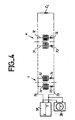
- the line is looped at its other end by an impedance Z c equal to its characteristic impedance, taking into account the load represented by the sensors.
- the pulses are reflected on the impedance discontinuities located along the line, and return to the generator 37.
- An oscillograph 38 for example, connected in parallel with the generator 37, makes it possible to identify the instants of departure and return of the pulses. The position of the reflective discontinuities on the line is then easily deduced therefrom.
- the right sensors of the left sensors of the junctions are dissymmetrical by connecting them to one of the wires of the line respectively by two diodes 33 and 34 mounted head to tail. By then sending pairs of pulses of opposite polarities, it can be recognized in an echo corresponding to a junction whether it is the sensor on the left, or that on the right, which is the source of the echo.
Landscapes
- Physics & Mathematics (AREA)
- Life Sciences & Earth Sciences (AREA)
- General Physics & Mathematics (AREA)
- Remote Sensing (AREA)
- Environmental & Geological Engineering (AREA)
- Geology (AREA)
- Acoustics & Sound (AREA)
- General Life Sciences & Earth Sciences (AREA)
- Engineering & Computer Science (AREA)
- Geophysics (AREA)
- Geophysics And Detection Of Objects (AREA)
- Examining Or Testing Airtightness (AREA)
- Investigating Or Analyzing Materials By The Use Of Electric Means (AREA)
Claims (2)
Applications Claiming Priority (2)
| Application Number | Priority Date | Filing Date | Title |
|---|---|---|---|
| FR8413510 | 1984-08-31 | ||
| FR8413510A FR2569847B1 (fr) | 1984-08-31 | 1984-08-31 | Dispositif de detection et de localisation d'entree d'eau pour flute marine |
Publications (2)
| Publication Number | Publication Date |
|---|---|
| EP0177384A1 EP0177384A1 (de) | 1986-04-09 |
| EP0177384B1 true EP0177384B1 (de) | 1988-12-14 |
Family
ID=9307355
Family Applications (1)
| Application Number | Title | Priority Date | Filing Date |
|---|---|---|---|
| EP85401681A Expired EP0177384B1 (de) | 1984-08-31 | 1985-08-23 | Vorrichtung zum Ermitteln und Lokalisieren eines Wassereintritts in eine akustische Unterswasserantenne |
Country Status (6)
| Country | Link |
|---|---|
| US (1) | US4695787A (de) |
| EP (1) | EP0177384B1 (de) |
| JP (1) | JPS6165130A (de) |
| AU (1) | AU575199B2 (de) |
| DE (1) | DE3566836D1 (de) |
| FR (1) | FR2569847B1 (de) |
Families Citing this family (21)
| Publication number | Priority date | Publication date | Assignee | Title |
|---|---|---|---|---|
| US4842477A (en) * | 1986-12-24 | 1989-06-27 | General Electric Company | Active clearance control |
| US5077526A (en) * | 1988-03-30 | 1991-12-31 | Automated Light Technologies, Inc. | Cable failure detection system |
| JPH01299445A (ja) * | 1988-05-27 | 1989-12-04 | Hitachi Ltd | 物理量または状態の変化検出装置 |
| US4949076A (en) * | 1988-10-13 | 1990-08-14 | Conoco Inc. | Apparatus for detecting and locating leakage in underwater structures |
| US5376888A (en) * | 1993-06-09 | 1994-12-27 | Hook; William R. | Timing markers in time domain reflectometry systems |
| US5748092A (en) * | 1996-04-24 | 1998-05-05 | Arsenault; Marc J. | Ceiling tile moisture detection system |
| KR100196535B1 (ko) * | 1996-07-16 | 1999-06-15 | 손욱 | 2차 전지 누액 감지 장치 |
| US6175310B1 (en) | 1999-05-10 | 2001-01-16 | Richard J. Gott | Leak detection tape |
| FR2801417B1 (fr) | 1999-11-19 | 2002-02-08 | Thomson Marconi Sonar Sas | Systeme de connexion pour antenne acoustique sous-marine |
| AUPS015702A0 (en) * | 2002-01-25 | 2002-02-14 | Thales Underwater Systems Pty Limited | Electronics carrying module |
| FR2880424B1 (fr) * | 2004-12-30 | 2008-10-10 | Airbus France Sas | Systeme de detection, de quantification et/ou de localisation d'eau dans des structures sandwich d'aeronef et procedes de mise en oeuvre de ce systeme |
| JP2007334311A (ja) * | 2006-05-18 | 2007-12-27 | Nippon Hoso Kyokai <Nhk> | 可視光・赤外光撮影光学系 |
| JP2009074818A (ja) * | 2007-09-19 | 2009-04-09 | Furukawa Electric Co Ltd:The | クロージャ |
| EP2706338B1 (de) * | 2012-09-10 | 2019-04-17 | GE Oil & Gas UK Limited | Detektionsvorrichtung und -verfahren |
| DE102013012566A1 (de) | 2013-07-29 | 2015-01-29 | Man Diesel & Turbo Se | Verfahren zum Betreiben einer Brennkraftmaschine |
| US9568626B2 (en) | 2014-06-12 | 2017-02-14 | Pgs Geophysical As | Flexible printed circuits in marine geophysical streamers |
| DE102014114752A1 (de) * | 2014-10-10 | 2016-04-14 | Krohne S. A. S. | Verfahren sowie Vorrichtung zur Füllstandsmessung |
| CN107923815B (zh) | 2015-06-30 | 2022-11-01 | 美国圣戈班性能塑料公司 | 泄漏检测系统 |
| JP7029884B2 (ja) * | 2017-04-13 | 2022-03-04 | 株式会社日立製作所 | 湿度検出素子及び湿度計 |
| KR102715995B1 (ko) * | 2017-11-27 | 2024-10-15 | 생-고뱅 퍼포먼스 플라스틱스 코포레이션 | 누출 검출 시스템 및 이를 제조하고 사용하는 방법 |
| US11137314B2 (en) * | 2018-03-07 | 2021-10-05 | Steering Solutions Ip Holding Corporation | Water intrusion detection |
Family Cites Families (11)
| Publication number | Priority date | Publication date | Assignee | Title |
|---|---|---|---|---|
| US3470554A (en) * | 1966-03-09 | 1969-09-30 | Johnson Service Co | Intrusion alarm system having authorization capability with tamper detection means |
| US3938385A (en) * | 1974-05-24 | 1976-02-17 | The United States Of America As Represented By The Secretary Of The Navy | Distributed temperature sensor |
| JPS5144979U (de) * | 1974-10-01 | 1976-04-02 | ||
| DE2550940C3 (de) * | 1975-11-13 | 1981-02-19 | Howaldtswerke-Deutsche Werft Ag Hamburg Und Kiel, 2300 Kiel | Einrichtung zum Feststellen von Feuchtigkeitsorten in wärmedämmenden Isolierungen von Rohrleitungen |
| DE2705045A1 (de) * | 1977-02-08 | 1978-08-10 | Howaldtswerke Deutsche Werft | Isolationsueberwachung fuer meldeleitungen mit abzweigungen in ueberwachungssystemen |
| US4109117A (en) * | 1977-09-02 | 1978-08-22 | The United States Of America As Represented By The Secretary Of The Navy | Range division multiplexing |
| JPS5499558A (en) * | 1978-01-23 | 1979-08-06 | Iwatsu Electric Co Ltd | Electron gun of cathode-ray tube |
| JPS5624542A (en) * | 1979-08-03 | 1981-03-09 | Omron Tateisi Electronics Co | Detecting method of leakage of liquid |
| FR2509053A1 (fr) * | 1981-07-02 | 1983-01-07 | Inst Francais Du Petrole | Dispositif de detection des entrees d'eau a l'interieur d'une flute sismique |
| US4455530A (en) * | 1982-03-30 | 1984-06-19 | Westinghouse Electric Corp. | Conductivity sensor for use in steam turbines |
| DE3322772C2 (de) * | 1983-06-24 | 1986-05-22 | Didier-Werke Ag, 6200 Wiesbaden | Verbundfolie zum Auskleiden von Flüssigkeitsbehältern |
-
1984
- 1984-08-31 FR FR8413510A patent/FR2569847B1/fr not_active Expired
-
1985
- 1985-08-23 DE DE8585401681T patent/DE3566836D1/de not_active Expired
- 1985-08-23 EP EP85401681A patent/EP0177384B1/de not_active Expired
- 1985-08-27 US US06/769,735 patent/US4695787A/en not_active Expired - Fee Related
- 1985-08-29 AU AU46881/85A patent/AU575199B2/en not_active Ceased
- 1985-08-30 JP JP60191810A patent/JPS6165130A/ja active Pending
Also Published As
| Publication number | Publication date |
|---|---|
| JPS6165130A (ja) | 1986-04-03 |
| DE3566836D1 (en) | 1989-01-19 |
| AU4688185A (en) | 1986-03-06 |
| FR2569847A1 (fr) | 1986-03-07 |
| EP0177384A1 (de) | 1986-04-09 |
| FR2569847B1 (fr) | 1988-02-05 |
| US4695787A (en) | 1987-09-22 |
| AU575199B2 (en) | 1988-07-21 |
Similar Documents
| Publication | Publication Date | Title |
|---|---|---|
| EP0177384B1 (de) | Vorrichtung zum Ermitteln und Lokalisieren eines Wassereintritts in eine akustische Unterswasserantenne | |
| US4949076A (en) | Apparatus for detecting and locating leakage in underwater structures | |
| US4797621A (en) | Leak detector and locator utilizing time domain reflectometry and sampling techniques | |
| FR2495784A1 (fr) | Appareil et procede pour determiner la position d'une flute marine remorquee par un navire | |
| EP0247908B1 (de) | Flüssigkeitspegelaufnehmer unter Benutzung elastisch gefühter Wellen | |
| FR2473721A1 (fr) | Dispositif a ultrasons pour l'indication de la presence de verglas sur une route asphaltee ou analogue | |
| US4228399A (en) | Offshore pipeline electrical survey method and apparatus | |
| EP0187103B1 (de) | Vertikaler Seeschleppkörper | |
| EP3492934B1 (de) | Vorrichtung und verfahren zur erkennung und lokalisierung eines kabelfehlers | |
| CA2748972A1 (en) | Systems and methods for detecting anomalies in elongate members using electromagnetic back scatter | |
| EP2614379A1 (de) | Verfahren und vorrichtung zur automatischen messung der physikalischen eigenschaften eines kabels, im besonderen der ausbreitungsgeschwindigkeit | |
| CA1299242C (fr) | Procede pour detecter des variations d'epaisseur dans la paroi d'un corps tubulaire conducteur d'electricite | |
| CA1191902A (fr) | Dispositif de detection des entrees d'eau a l'interieur d'une flute sismique | |
| FR2483618A1 (fr) | Procede et appareil de detection et de mesure de corrosion | |
| CA1177571A (fr) | Methode pour determiner le pendage de formations geologiques traversees par un sondage | |
| EP0180501B1 (de) | Vorrichtung zur Feststellung und Festlegung eines Fehlers in einer Seilschwebebahneinrichtung | |
| EP0077757B1 (de) | Verfahren zur Fehlererkennung einer dielektrischen Schicht an der Oberfläche eines elektrisch leitenden Substrats | |
| FR2790087A1 (fr) | Procede et dispositif de mesure in situ de la distance entre deux elements donnes dans une conduite tubulaire | |
| EP0165852B1 (de) | Vorrichtung zum Messen durch Ultraschall des Flüssigkeitstandes und/oder Volumens in einem Behälter | |
| EP0136238A1 (de) | Vorrichtung zur Messung der Nähe einer metallisch leitenden Oberfläche | |
| FR3015052A1 (de) | ||
| FR2701566A1 (fr) | Procédé de mesure d'au moins une caractéristique d'une solution liquide et moyens pour la mise en Óoeuvre de la dite solution. | |
| EP0642671B1 (de) | Sondenvorrichtung und verfahren zur messung des bodenwiderstandes | |
| FR2588968A1 (fr) | Dispositif de detection d'ondes sismiques et installation de prospection sismique marine monotrage comportant un tel dispositif | |
| FR2688891A1 (fr) | Dispositif de test d'un groupement de recepteurs. |
Legal Events
| Date | Code | Title | Description |
|---|---|---|---|
| PUAI | Public reference made under article 153(3) epc to a published international application that has entered the european phase |
Free format text: ORIGINAL CODE: 0009012 |
|
| AK | Designated contracting states |
Kind code of ref document: A1 Designated state(s): DE GB NL |
|
| 17P | Request for examination filed |
Effective date: 19860912 |
|
| 17Q | First examination report despatched |
Effective date: 19871013 |
|
| GRAA | (expected) grant |
Free format text: ORIGINAL CODE: 0009210 |
|
| AK | Designated contracting states |
Kind code of ref document: B1 Designated state(s): DE GB NL |
|
| PG25 | Lapsed in a contracting state [announced via postgrant information from national office to epo] |
Ref country code: NL Effective date: 19881214 |
|
| GBT | Gb: translation of ep patent filed (gb section 77(6)(a)/1977) | ||
| REF | Corresponds to: |
Ref document number: 3566836 Country of ref document: DE Date of ref document: 19890119 |
|
| NLV1 | Nl: lapsed or annulled due to failure to fulfill the requirements of art. 29p and 29m of the patents act | ||
| RAP4 | Party data changed (patent owner data changed or rights of a patent transferred) |
Owner name: THOMSON-CSF |
|
| PLBE | No opposition filed within time limit |
Free format text: ORIGINAL CODE: 0009261 |
|
| STAA | Information on the status of an ep patent application or granted ep patent |
Free format text: STATUS: NO OPPOSITION FILED WITHIN TIME LIMIT |
|
| 26N | No opposition filed | ||
| PGFP | Annual fee paid to national office [announced via postgrant information from national office to epo] |
Ref country code: DE Payment date: 19910718 Year of fee payment: 7 |
|
| PGFP | Annual fee paid to national office [announced via postgrant information from national office to epo] |
Ref country code: GB Payment date: 19910722 Year of fee payment: 7 |
|
| PG25 | Lapsed in a contracting state [announced via postgrant information from national office to epo] |
Ref country code: GB Effective date: 19920823 |
|
| GBPC | Gb: european patent ceased through non-payment of renewal fee |
Effective date: 19920823 |
|
| PG25 | Lapsed in a contracting state [announced via postgrant information from national office to epo] |
Ref country code: DE Effective date: 19930501 |