EP0177433A2 - Leakage detection and tracking system - Google Patents
Leakage detection and tracking system Download PDFInfo
- Publication number
- EP0177433A2 EP0177433A2 EP85630121A EP85630121A EP0177433A2 EP 0177433 A2 EP0177433 A2 EP 0177433A2 EP 85630121 A EP85630121 A EP 85630121A EP 85630121 A EP85630121 A EP 85630121A EP 0177433 A2 EP0177433 A2 EP 0177433A2
- Authority
- EP
- European Patent Office
- Prior art keywords
- nacelle
- air
- signal
- leakage
- flow
- Prior art date
- Legal status (The legal status is an assumption and is not a legal conclusion. Google has not performed a legal analysis and makes no representation as to the accuracy of the status listed.)
- Granted
Links
Images

Classifications
-
- G—PHYSICS
- G01—MEASURING; TESTING
- G01M—TESTING STATIC OR DYNAMIC BALANCE OF MACHINES OR STRUCTURES; TESTING OF STRUCTURES OR APPARATUS, NOT OTHERWISE PROVIDED FOR
- G01M3/00—Investigating fluid-tightness of structures
- G01M3/02—Investigating fluid-tightness of structures by using fluid or vacuum
- G01M3/26—Investigating fluid-tightness of structures by using fluid or vacuum by measuring rate of loss or gain of fluid, e.g. by pressure-responsive devices, by flow detectors
Definitions
- This invention relates to nacelles for aircraft powered by a turbine type power plant and particularly to means for ascertaining and tracking air leakage within the nacelle.
- the temperature and pressure being monitored would be recorded by an on-board flight data recording instrument and this data would be fed to a suitable computer on the ground or within the aircraft to obtain the necessary calculations.
- An object of this invention is to provide for aircraft means for tracking the leakage from the nacelle and calculate it in terms of loss of TSFC.
- a feature of this invention is to measure the pressure differential between air pressure outside the nacelle and within the nacelle during periods of time when a given air flow is added to the nacelle and without the given air' flow.
- Another feature of this invention is to include a temperature sensor to aid in determining the source of the leakage.
- Fig. 1 is an illustration, partly in section and partly in schematic, of this invention.
- Fig. 2 is a graphical representation of an isentropic flow curve.
- a turbine type power plant (fan/jet) 10 is housed in the nacelle generally indicated by reference numeral 12.
- a bypass duct 14 is typically formed by the nacelle for leading fan air overboard.
- this embodiment incorporates an active clearance control and reference should be made to the 4,069,662 patent, supra, for details thereof. Suffice it to say, fan discharge air is bled from the discharge duct 14 into manifold 16 for feeding spray bars 16 and 18. The spray bars flow the air onto the engine casing to cause it to shrink in order to control the tip clearance of the rotating blades (compressor and/or turbine). This air flows either rearwardly and discharges with the engine discharge air or leaks through the skin of the nacelle as does other leakages within the nacelle. These leakage paths are not shown as it is obvious that nacelles in current use are notorious for their leakage problems.
- the invention serves to measure and track this leakage and compute it in terms of assisting those concerned with maintenance to ascertain when to fix such leakages. Further, the invention contemplates sensing the temperature to ascertain the source of such leakage.
- the pressure differential by a suitable pressure differential transducer senses the pressure inside the nacelle by a suitable pressure tap and line 22 and the pressure outside the nacelle by a suitable pressure tap and line 24.
- the transducer converts these'values to produce an output signal indicative of the differential which is either recorded in a flight data recorder or fed to a computer directly.
- the computer may be a special or general purpose computer that calculates the value and compares it to values of pressure differential signals that have to be obtained when a given air flow was injected into the nacelle.
- This value can then be converted into fuel consumption loss.
Landscapes
- Physics & Mathematics (AREA)
- General Physics & Mathematics (AREA)
- Examining Or Testing Airtightness (AREA)
- Turbine Rotor Nozzle Sealing (AREA)
Abstract
Description
- This invention relates to nacelles for aircraft powered by a turbine type power plant and particularly to means for ascertaining and tracking air leakage within the nacelle.
- As is well known, air leakage from the nacelle occasioned by the many ducts, flanges, joints and connections in the power plant and nacelle create a source of drag to the aircraft, and lost engine work, and consequently a reduction in fuel economy. Obviously, because of the high cost of fuel it becomes abundantly important to be able to ascertain this leakage and compute it in terms of loss of thrust specific fuel consumption (TSFC). This enables the aircraft operator to determine whether it is more expedient to remove the aircraft from service to resolve the leakage problem or to leave the aircraft in service notwithstanding the extra cost resulting from the loss of TSFC. Hence, as is apparent, it would be an advantage in this decision making process to track the leakage from the nacelle and calculate the leakage in terms of loss of TSFC as well as to ascertain the source of the leakage.
- To this end, we have found that we can track the leakage from the nacelle of aircraft by measuring the pressure difference between the interior of the nacelle and the exterior of the nacelle (ambient) and compute its value relative to a known quantity of air admitted into the nacelle. In this manner we can achieve a representative leakage value notwithstanding the fact the leakage area and leakage discharge coefficient of the leaking orifices are unknown. By use of a general or special purpose computer, which is typically available either on ground or in the aircraft, this value can be tracked continuously and either converted in terms of TSFC loss or used as a standard to establish maintenance procedures. By measuring the temperature of the air within the nacelle, it is possible to ascertain whether the leak is from a cool source or a hot source. The temperature data would also have an effect on the TSFC value inasmuch as a leak from a hotter station in the engine gas path has a greater influence on TSFC than does a leak from a lower temperature source.
- In certain installations it is contemplated that the temperature and pressure being monitored would be recorded by an on-board flight data recording instrument and this data would be fed to a suitable computer on the ground or within the aircraft to obtain the necessary calculations.
- An object of this invention is to provide for aircraft means for tracking the leakage from the nacelle and calculate it in terms of loss of TSFC. A feature of this invention is to measure the pressure differential between air pressure outside the nacelle and within the nacelle during periods of time when a given air flow is added to the nacelle and without the given air' flow.
- Another feature of this invention is to include a temperature sensor to aid in determining the source of the leakage.
- Other features and advantages will be apparent from the specification and claims and from the accompanying drawings which illustrate an embodiment of the invention.
- Fig. 1 is an illustration, partly in section and partly in schematic, of this invention.
- Fig. 2 is a graphical representation of an isentropic flow curve.
- While this invention is described in its preferred embodiment being employed with a fan/jet type power plant, as will be apparent to one skilled in the art, it is applicable to any type of power plant that is housed in a nacelle. Also, although the system to be described is conveniently employed where active clearance control (ACC) of the type that flows air on the exterior of the engine case such as that described in U.S. Patent No. 4,069,662 granted to I.H. Redinger, Jr. et al on January 24, 1978'and assigned to the same assignee of this patent application is used, this is not a necessary element to practice this invention.
- As noted from Figure 1, a turbine type power plant (fan/jet) 10 is housed in the nacelle generally indicated by
reference numeral 12. In the fan type engine as shown, abypass duct 14 is typically formed by the nacelle for leading fan air overboard. As mentioned above, this embodiment incorporates an active clearance control and reference should be made to the 4,069,662 patent, supra, for details thereof. Suffice it to say, fan discharge air is bled from thedischarge duct 14 intomanifold 16 for feedingspray bars 16 and 18. The spray bars flow the air onto the engine casing to cause it to shrink in order to control the tip clearance of the rotating blades (compressor and/or turbine). This air flows either rearwardly and discharges with the engine discharge air or leaks through the skin of the nacelle as does other leakages within the nacelle. These leakage paths are not shown as it is obvious that nacelles in current use are notorious for their leakage problems. - The invention serves to measure and track this leakage and compute it in terms of assisting those concerned with maintenance to ascertain when to fix such leakages. Further, the invention contemplates sensing the temperature to ascertain the source of such leakage.
- In accordance with this invention the pressure differential by a suitable pressure differential transducer generally indicated by
reference numeral 20 senses the pressure inside the nacelle by a suitable pressure tap andline 22 and the pressure outside the nacelle by a suitable pressure tap andline 24. The transducer converts these'values to produce an output signal indicative of the differential which is either recorded in a flight data recorder or fed to a computer directly. The computer may be a special or general purpose computer that calculates the value and compares it to values of pressure differential signals that have to be obtained when a given air flow was injected into the nacelle. - Obviously, in installations that employ active clearance controls of the type described in U.S. Patent No. 4,069,662 this air may be obtained by flowing the air through the spray bars. The purpose of measuring the pressure differential before and after the known flow injection will be apparent from the following discussion.
- Since the area of the leakage openings vary considerably and continously, and since the discharge coefficient is not conveniently known, the calculations presented will account for these unknown by making proportions when a given flow is injected into the nacelle to when this flow is shut off. By making these proportions or ratios, the leakage can be calculated in terms of TSFC with sufficient degree of accuracy to prognosticate when these leakages should be attended to. The best way of understanding the calculations necessary to arrive at these ratios is by considering the following example.
- In this example the following symbols will be used.
- P = pressure
- P = pressure within the nacelle
- Pa = pressure outside the nacelle or (ambient)
- w = air flow #/sec
- T = temperature
- A = total leakage area
- PSIA = pounds per square inch absolute
- CD= overboard leakage's discharge coefficient
- Assume the following measurements


- Calculate the pressure ratio (aircraft instrumentation is suitable to convert the pressure differential signal to the ratio signal).

- From the well known isentropic curve depicted in Fig. 2

- Assume the active clearance control (ACC) when turned on flows 1.0#/sec (WACC) (other means can be utilized to flow a given quantity of air).
- Assume Pc' (after ACC is turned on) measures 4.25 PSIA.
- Calculate the pressure ratio as follows
-

-


is as follows
- The area value cancels out, along with the discharge coefficient. Pc, Pc', T, and T' are measured.
- Since

- Therefore,
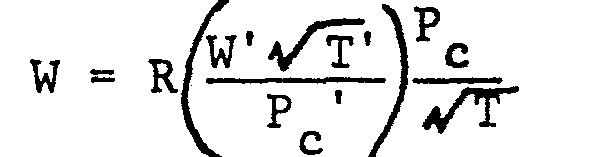

- Solving for leakage flow (W) gives

- This value can then be converted into fuel consumption loss.
- Assume the temperature sensed was 300°.
- This compared to the normal 400° temperature (without leakage) would indicate that at say, 35,000 ft. alt. this is below normal and the leak is from the fan air.
- It should be understood that the invention is not limited to the particular embodiments shown and described herein, but that various changes and modifications may be made without departing from the spirit and scope of this novel concept as defined by the following claims.
Claims (4)
Applications Claiming Priority (2)
| Application Number | Priority Date | Filing Date | Title |
|---|---|---|---|
| US06/655,123 US4621520A (en) | 1984-09-26 | 1984-09-26 | Leakage detection and tracking system |
| US655123 | 1984-09-26 |
Publications (3)
| Publication Number | Publication Date |
|---|---|
| EP0177433A2 true EP0177433A2 (en) | 1986-04-09 |
| EP0177433A3 EP0177433A3 (en) | 1987-09-16 |
| EP0177433B1 EP0177433B1 (en) | 1989-10-04 |
Family
ID=24627625
Family Applications (1)
| Application Number | Title | Priority Date | Filing Date |
|---|---|---|---|
| EP85630121A Expired EP0177433B1 (en) | 1984-09-26 | 1985-08-01 | Leakage detection and tracking system |
Country Status (4)
| Country | Link |
|---|---|
| US (1) | US4621520A (en) |
| EP (1) | EP0177433B1 (en) |
| JP (1) | JPS6183457A (en) |
| DE (2) | DE3573475D1 (en) |
Cited By (5)
| Publication number | Priority date | Publication date | Assignee | Title |
|---|---|---|---|---|
| US6539776B2 (en) | 2000-06-19 | 2003-04-01 | Structural Monitoring Systems, Ltd. | Apparatus for condition monitoring of the integrity of fasteners and fastened joints |
| US6591661B2 (en) | 2000-05-30 | 2003-07-15 | Structural Monitoring Systems Ltd. | Apparatus and method for measurement of permeability or strain in permeable materials |
| US6715365B2 (en) | 2000-05-03 | 2004-04-06 | Structural Monitoring Systems, Ltd. | System and method for the detection and propagation measurement of flaws in a component or structure |
| US6720882B2 (en) | 2001-01-18 | 2004-04-13 | Structural Monitoring Systems Ltd. | Self-monitoring method and apparatus for condition monitoring of a structure |
| US7500383B2 (en) | 2001-07-13 | 2009-03-10 | Structural Monitoring Systems, Ltd. | Method and apparatus for monitoring the integrity of components and structures |
Families Citing this family (7)
| Publication number | Priority date | Publication date | Assignee | Title |
|---|---|---|---|---|
| JP3344046B2 (en) * | 1993-12-22 | 2002-11-11 | 豊田合成株式会社 | Leak amount detection device |
| JP2006224054A (en) * | 2005-02-21 | 2006-08-31 | Matsushita Electric Ind Co Ltd | Electric dust collection unit |
| JP4770201B2 (en) * | 2005-03-08 | 2011-09-14 | パナソニック株式会社 | Electric dust collection unit |
| US8562289B2 (en) * | 2010-02-26 | 2013-10-22 | Ge Aviation Systems, Llc | Method and system for a leakage controlled fan housing |
| US9458855B2 (en) * | 2010-12-30 | 2016-10-04 | Rolls-Royce North American Technologies Inc. | Compressor tip clearance control and gas turbine engine |
| US11300365B2 (en) * | 2018-06-19 | 2022-04-12 | General Electric Company | Heat exchanger and leak detection system |
| US11846568B2 (en) * | 2021-06-09 | 2023-12-19 | Pratt & Whitney Canada Corp. | Leak detection for pressurized fluid systems |
Family Cites Families (6)
| Publication number | Priority date | Publication date | Assignee | Title |
|---|---|---|---|---|
| US3593567A (en) * | 1969-06-09 | 1971-07-20 | Ezra D Hartley | Leak checker |
| US3673855A (en) * | 1971-03-10 | 1972-07-04 | Lockheed Aircraft Corp | Leakage flow monitor |
| US3918291A (en) * | 1973-03-05 | 1975-11-11 | Sterer Engineering & Mfg Co | Method and apparatus for testing leakage rate |
| JPS5566730A (en) * | 1978-10-30 | 1980-05-20 | Sumitomo Metal Ind Ltd | Micro leakage detector for pipeline |
| US4363236A (en) * | 1980-04-28 | 1982-12-14 | Meyers Harry W | Method and apparatus for detecting leaks in a structure |
| DE8023502U1 (en) * | 1980-09-03 | 1981-01-22 | Alkem Gmbh, 6450 Hanau | TRANSPORTABLE TIGHTNESS TEST DEVICE |
-
1984
- 1984-09-26 US US06/655,123 patent/US4621520A/en not_active Expired - Lifetime
-
1985
- 1985-08-01 DE DE8585630121T patent/DE3573475D1/en not_active Expired
- 1985-08-01 DE DE198585630121T patent/DE177433T1/en active Pending
- 1985-08-01 EP EP85630121A patent/EP0177433B1/en not_active Expired
- 1985-08-19 JP JP60181585A patent/JPS6183457A/en active Granted
Cited By (5)
| Publication number | Priority date | Publication date | Assignee | Title |
|---|---|---|---|---|
| US6715365B2 (en) | 2000-05-03 | 2004-04-06 | Structural Monitoring Systems, Ltd. | System and method for the detection and propagation measurement of flaws in a component or structure |
| US6591661B2 (en) | 2000-05-30 | 2003-07-15 | Structural Monitoring Systems Ltd. | Apparatus and method for measurement of permeability or strain in permeable materials |
| US6539776B2 (en) | 2000-06-19 | 2003-04-01 | Structural Monitoring Systems, Ltd. | Apparatus for condition monitoring of the integrity of fasteners and fastened joints |
| US6720882B2 (en) | 2001-01-18 | 2004-04-13 | Structural Monitoring Systems Ltd. | Self-monitoring method and apparatus for condition monitoring of a structure |
| US7500383B2 (en) | 2001-07-13 | 2009-03-10 | Structural Monitoring Systems, Ltd. | Method and apparatus for monitoring the integrity of components and structures |
Also Published As
| Publication number | Publication date |
|---|---|
| EP0177433B1 (en) | 1989-10-04 |
| EP0177433A3 (en) | 1987-09-16 |
| DE3573475D1 (en) | 1989-11-09 |
| US4621520A (en) | 1986-11-11 |
| DE177433T1 (en) | 1986-07-24 |
| JPH0520569B2 (en) | 1993-03-19 |
| JPS6183457A (en) | 1986-04-28 |
Similar Documents
| Publication | Publication Date | Title |
|---|---|---|
| EP0177433B1 (en) | Leakage detection and tracking system | |
| US6473705B1 (en) | System and method for direct non-intrusive measurement of corrected airflow | |
| Powrie et al. | Engine health monitoring: Towards total prognostics | |
| CA1096643A (en) | Surge detector for gas turbine engines | |
| US12264990B2 (en) | Method and a system for monitoring the state of an exchanger in an air circuit of an aircraft | |
| US5152169A (en) | Gas turbine engine thrust measurement | |
| US5680310A (en) | Method and apparatus for sensing a steady state engine condition using a trending algorithm | |
| EP0273849A2 (en) | Inlet total temperature synthesis for gas turbine engines | |
| CA2136933C (en) | Diagnostic performance testing for gas turbine engines | |
| CA1160345A (en) | Determination of gross thrust-related parameters | |
| US3886790A (en) | Apparatus for determining the gross thrust of a jet engine | |
| Dyson et al. | CF6-80 condition monitoring-The engine manufacturer's involvement in data acquisition and analysis | |
| Walsh et al. | Inlet distortion for an F/A-18A aircraft during steady aerodynamic conditions up to 60° angle of attack | |
| Mersinligil et al. | High-temperature high-frequency turbine exit flow field measurements in a military engine with a cooled unsteady total pressure probe | |
| Farr | Evaluation of F-15 inlet dynamic distortion | |
| Neese | Use of Expanded AIDS in Engine Health Monitoring on the CF6-80 Engine for the A310 Airbus | |
| SU987443A1 (en) | Axial compressor technological condition evaluation method | |
| THOMPSON | An overview of the application of standard measurement uncertainty methodology to propulsion testing | |
| BARRETT et al. | State-of-the-art review of turbine engine checkout techniques | |
| Lo et al. | Wind-tunnel compressor stall monitoring using neural networks | |
| Turczeniuk | Exhaust Gas Reingestion Measurements | |
| Rabe et al. | Acquisition of F-100 (3) High Pressure Compressor Entrance Profiles | |
| CASSANTO et al. | An experiment to determine nose tip transition with fluctuating pressure measurements/ground test data | |
| STEVENS | Instrumentation for an engine diagnostic system | |
| Dean et al. | Data Acquisition and Processing in the NGTE Altitude Test Facility |
Legal Events
| Date | Code | Title | Description |
|---|---|---|---|
| PUAI | Public reference made under article 153(3) epc to a published international application that has entered the european phase |
Free format text: ORIGINAL CODE: 0009012 |
|
| AK | Designated contracting states |
Kind code of ref document: A2 Designated state(s): DE FR GB |
|
| EL | Fr: translation of claims filed | ||
| DET | De: translation of patent claims | ||
| PUAL | Search report despatched |
Free format text: ORIGINAL CODE: 0009013 |
|
| AK | Designated contracting states |
Kind code of ref document: A3 Designated state(s): DE FR GB |
|
| 17P | Request for examination filed |
Effective date: 19871119 |
|
| 17Q | First examination report despatched |
Effective date: 19880817 |
|
| GRAA | (expected) grant |
Free format text: ORIGINAL CODE: 0009210 |
|
| AK | Designated contracting states |
Kind code of ref document: B1 Designated state(s): DE FR GB |
|
| ET | Fr: translation filed | ||
| REF | Corresponds to: |
Ref document number: 3573475 Country of ref document: DE Date of ref document: 19891109 |
|
| PLBE | No opposition filed within time limit |
Free format text: ORIGINAL CODE: 0009261 |
|
| STAA | Information on the status of an ep patent application or granted ep patent |
Free format text: STATUS: NO OPPOSITION FILED WITHIN TIME LIMIT |
|
| 26N | No opposition filed | ||
| PGFP | Annual fee paid to national office [announced via postgrant information from national office to epo] |
Ref country code: FR Payment date: 19920713 Year of fee payment: 8 |
|
| PGFP | Annual fee paid to national office [announced via postgrant information from national office to epo] |
Ref country code: GB Payment date: 19920715 Year of fee payment: 8 |
|
| PGFP | Annual fee paid to national office [announced via postgrant information from national office to epo] |
Ref country code: DE Payment date: 19920720 Year of fee payment: 8 |
|
| PG25 | Lapsed in a contracting state [announced via postgrant information from national office to epo] |
Ref country code: GB Effective date: 19930801 |
|
| GBPC | Gb: european patent ceased through non-payment of renewal fee |
Effective date: 19930801 |
|
| PG25 | Lapsed in a contracting state [announced via postgrant information from national office to epo] |
Ref country code: FR Effective date: 19940429 |
|
| PG25 | Lapsed in a contracting state [announced via postgrant information from national office to epo] |
Ref country code: DE Effective date: 19940503 |
|
| REG | Reference to a national code |
Ref country code: FR Ref legal event code: ST |