EP0177473B1 - Dispositif de montage amovible d'un montant sur la plate-forme d'un véhicule et d'une ridelle sur le montant - Google Patents
Dispositif de montage amovible d'un montant sur la plate-forme d'un véhicule et d'une ridelle sur le montant Download PDFInfo
- Publication number
- EP0177473B1 EP0177473B1 EP85850301A EP85850301A EP0177473B1 EP 0177473 B1 EP0177473 B1 EP 0177473B1 EP 85850301 A EP85850301 A EP 85850301A EP 85850301 A EP85850301 A EP 85850301A EP 0177473 B1 EP0177473 B1 EP 0177473B1
- Authority
- EP
- European Patent Office
- Prior art keywords
- post
- locking member
- lever
- sideboard
- platform
- Prior art date
- Legal status (The legal status is an assumption and is not a legal conclusion. Google has not performed a legal analysis and makes no representation as to the accuracy of the status listed.)
- Expired - Lifetime
Links
- 230000033001 locomotion Effects 0.000 claims description 13
- 238000012423 maintenance Methods 0.000 claims 1
- 210000002105 tongue Anatomy 0.000 description 10
- 230000006835 compression Effects 0.000 description 2
- 238000007906 compression Methods 0.000 description 2
- 210000005069 ears Anatomy 0.000 description 2
- 230000003014 reinforcing effect Effects 0.000 description 2
- 208000027418 Wounds and injury Diseases 0.000 description 1
- 230000006378 damage Effects 0.000 description 1
- 230000002349 favourable effect Effects 0.000 description 1
- 208000014674 injury Diseases 0.000 description 1
Images


Classifications
-
- E—FIXED CONSTRUCTIONS
- E05—LOCKS; KEYS; WINDOW OR DOOR FITTINGS; SAFES
- E05C—BOLTS OR FASTENING DEVICES FOR WINGS, SPECIALLY FOR DOORS OR WINDOWS
- E05C1/00—Fastening devices with bolts moving rectilinearly
- E05C1/02—Fastening devices with bolts moving rectilinearly without latching action
- E05C1/06—Fastening devices with bolts moving rectilinearly without latching action with operating handle or equivalent member moving otherwise than rigidly with the bolt
- E05C1/065—Fastening devices with bolts moving rectilinearly without latching action with operating handle or equivalent member moving otherwise than rigidly with the bolt flush
-
- B—PERFORMING OPERATIONS; TRANSPORTING
- B62—LAND VEHICLES FOR TRAVELLING OTHERWISE THAN ON RAILS
- B62D—MOTOR VEHICLES; TRAILERS
- B62D33/00—Superstructures for load-carrying vehicles
- B62D33/02—Platforms; Open load compartments
- B62D33/0207—Connections of movable or detachable racks or stanchions to platforms
Definitions
- the present invention relates to a device for removably attaching a post to a load platform, and a sideboard or the like to the post, the device including at least a first and at least a second locking member displaceably mounted on the post, these members being adapted respectively to engage with the sideboard and platform, and be operated by a single lever accessible from the exterior of the post, the lever being pivotably mounted on the first locking member and via at least one link being connected to the second locking member, and a detent means for ensuring that when the lever is swung to release the post from the platform and the sideboard from the post the second locking member is not taken out of engagement with the platform until the first locking member has been released from the sideboard.
- a device of the kind described above is already known from the Swedish patent specification SE ⁇ B ⁇ 320 275.
- Other, similar devices are known from such as the German Offenlegungsschriften DE-A-3 108 930, DE-A-2 706 063, the Swedish patent specifications SE ⁇ B ⁇ 218 048 and SE ⁇ B ⁇ 379 701 and the Swedish patent application SE-B-443 542.
- a disadvantage burdening several of the above- mentioned devices of the prior art is that when only the sideboard is to be released from the post, the post itself must be sometimes at least partially released from the platform, which can cause large problems.
- a still further disadvantage is that a large number of details is required to achieve the desired safety for releasing the sideboard from the post before releasing the post from the platform, that these details have a complicated shape and are difficult to assemble and dismantle, and that the complicated coaction and motions of the details involve unreliable function.
- a still further disadvantage is that the lever in the final phase of its opening motion can unintentionally cause, due to recoil action, movement of the locking means associated with the post, away from its locked position.
- An object of the present invention is to mitigate the disadvantages with previously known devices of the kind mentioned above.
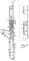
- a post 2 being removably attached to the platform, which is provided with a hook 1a and a stirrup 1b coacting with the post and with a locking member fastened thereto.
- the post is also provided with a further locking member for releasable connecting between the post and a sideboard 3 thrusting into the post with stirrup-shaped members, of which one, 3a, is illustrated. Both locking members are operated by a lever 4 mounted on the post.
- the post 2 is provided with an internal, elongate, U-shaped reinforcing member 2b and a reinforcing plate 5 engaging against the platform edge.
- the lower edge 5a of this plate is inserted between the platform edge and the hook 1a so that the post cannot be displaced horizontally in relation to the platform. In this position a lower horizontal portion of the post rests against the upper side of the hook 1a.
- the locking member for removable attachment of the post 2 to the platform 1 includes an elongate wedge 6, which is movable into and out of the stirrup 1 thrusting into a hole in the plate 5.
- the wedge 6 is provided with a shaft 7, on which one end of a link 15 is pivotably fastened.
- the other end of the link 15 is pivotably fastened to the lever 4 via a shaft 10.
- the second locking member for removable attachment of the sideboard 3 to the post 2 includes two tongues 8 and 9, which are movable into and out from the sideboard stirrups 3a when the sideboard is lifted up and engages against the post.
- the tongues 8 and 9 are mutually interconnected by a rod 11, guided for movement in the longitudinal direction of the post.
- the rod 11 is also connected to a U-shaped member 12, which is guided for movement in the longitudinal direction inside the U-shaped member 2b, the member 12 being provided with ears 12a and 12b connected with each other via a shaft 14.
- the lever 4 has a U-shaped cross section, and one end of it is pivotably mounted on the shaft 14.
- a helical spring 21 is placed round a shaft 13, fastened between the ears 12a and 12b, and one end of the spring terminates in a limb 21 inserted in a notch on the end of the lever 4 at the shaft 14, while the other spring end terminates in a limb 21b engaging againstthe member 12, as is illustrated in Figures 1 and 2.
- lever 4 is thus illustrated as taken to its clockwise end position, where the wedge 6 is completely withdrawn from the stirrup 1b. This position is stable, since the spring 21 is biassed against the lever 4.
- the post may be removed from the platform 1 by first swinging the post anticlockwise about the hook 1a and then lifting the post from it.
- a resilient member in the form of a compression spring 22 surrounds the rod 11 and is inserted between the member 2b and a ring 23 fastened to the rod 11 and the tongue 8. This spring dampens the movement of rod and tongues, and thereby the movement of the lever in the final phase of the opening movement, thus preventing movement of the wedge 6 from the locking position due to a possible recoil action caused by the springs 20 and 21, should the lever unexpectedly swing up to the position in Figure 4.
Landscapes
- Engineering & Computer Science (AREA)
- Mechanical Engineering (AREA)
- Chemical & Material Sciences (AREA)
- Combustion & Propulsion (AREA)
- Transportation (AREA)
- Supports Or Holders For Household Use (AREA)
- Refuge Islands, Traffic Blockers, Or Guard Fence (AREA)
- Fittings On The Vehicle Exterior For Carrying Loads, And Devices For Holding Or Mounting Articles (AREA)
- Medicines Containing Antibodies Or Antigens For Use As Internal Diagnostic Agents (AREA)
- Production Of Liquid Hydrocarbon Mixture For Refining Petroleum (AREA)
- Other Investigation Or Analysis Of Materials By Electrical Means (AREA)
- Manufacturing Of Tubular Articles Or Embedded Moulded Articles (AREA)
- Basic Packing Technique (AREA)
- Vehicle Step Arrangements And Article Storage (AREA)
- Handcart (AREA)
- Slide Fasteners, Snap Fasteners, And Hook Fasteners (AREA)
- Spinning Or Twisting Of Yarns (AREA)
- Financial Or Insurance-Related Operations Such As Payment And Settlement (AREA)
- Closing And Opening Devices For Wings, And Checks For Wings (AREA)
- Forklifts And Lifting Vehicles (AREA)
Claims (4)
Priority Applications (1)
| Application Number | Priority Date | Filing Date | Title |
|---|---|---|---|
| AT85850301T ATE50218T1 (de) | 1984-10-01 | 1985-09-30 | Einrichtung zum loesbarbefestigen einer runge auf eine ladeplattform und einer bordwand auf diese runge. |
Applications Claiming Priority (2)
| Application Number | Priority Date | Filing Date | Title |
|---|---|---|---|
| SE8404902A SE454972B (sv) | 1984-10-01 | 1984-10-01 | Anordning vid lostagbar fastsettning av en stolpe vid ett lastflak och en lem eller liknande vid stolpen |
| SE8404902 | 1984-10-01 |
Publications (3)
| Publication Number | Publication Date |
|---|---|
| EP0177473A2 EP0177473A2 (fr) | 1986-04-09 |
| EP0177473A3 EP0177473A3 (en) | 1988-03-30 |
| EP0177473B1 true EP0177473B1 (fr) | 1990-02-07 |
Family
ID=20357191
Family Applications (1)
| Application Number | Title | Priority Date | Filing Date |
|---|---|---|---|
| EP85850301A Expired - Lifetime EP0177473B1 (fr) | 1984-10-01 | 1985-09-30 | Dispositif de montage amovible d'un montant sur la plate-forme d'un véhicule et d'une ridelle sur le montant |
Country Status (6)
| Country | Link |
|---|---|
| EP (1) | EP0177473B1 (fr) |
| AT (1) | ATE50218T1 (fr) |
| DE (1) | DE3575894D1 (fr) |
| FI (1) | FI79988C (fr) |
| NO (1) | NO161480C (fr) |
| SE (1) | SE454972B (fr) |
Families Citing this family (7)
| Publication number | Priority date | Publication date | Assignee | Title |
|---|---|---|---|---|
| DE3732414A1 (de) * | 1986-09-26 | 1988-04-21 | Martinez Eugenio Anto Archanco | Vorrichtung fuer den schnellen an- und abbau eines pfeilers an der ladebruecke eines lastwagens |
| AU8227391A (en) * | 1990-07-09 | 1992-02-04 | Goran Rosen | A method of manufacturing stanchions for load platforms and a stanchion manufactured according to the method |
| AU656002B2 (en) * | 1991-08-09 | 1995-01-19 | Eldridge, Brenton Andrew | Swing gate |
| SE468759B (sv) * | 1992-02-14 | 1993-03-15 | Sven Erik Goeran Rosen | Stolpe till fordonslastflak |
| SE503361C2 (sv) * | 1994-09-01 | 1996-06-03 | Rosen Goran | Stolpe till fordonslastflak med en i stolpen inbyggd låsmekanism |
| ES2288782B1 (es) * | 2002-03-14 | 2009-10-15 | Mecanizados Rodriguez Fernandez, S.L. | Pilar para bastidores de carrocerias de vehiculos de carga. |
| DE102006049557A1 (de) * | 2006-10-20 | 2008-04-24 | Franz Xaver Meiller Fahrzeug- Und Maschinenfabrik - Gmbh & Co Kg | Riegelelement zur Sicherung eines Pendelzapfens einer Kippbrückenbordwand in einer Pendelzapfenaufnahme an einem Bordwandhalteelement |
Family Cites Families (2)
| Publication number | Priority date | Publication date | Assignee | Title |
|---|---|---|---|---|
| SE218048C1 (fr) * | 1965-10-04 | 1968-01-02 | ||
| SE443542B (sv) * | 1982-11-17 | 1986-03-03 | Nordisk Excenter Karosseri | Anordning for lostagbar fastsettning av en stolpe vid ett lastflak och en lem eller liknande vid stolpen |
-
1984
- 1984-10-01 SE SE8404902A patent/SE454972B/sv not_active IP Right Cessation
-
1985
- 1985-09-30 NO NO853843A patent/NO161480C/no unknown
- 1985-09-30 EP EP85850301A patent/EP0177473B1/fr not_active Expired - Lifetime
- 1985-09-30 DE DE8585850301T patent/DE3575894D1/de not_active Expired - Fee Related
- 1985-09-30 AT AT85850301T patent/ATE50218T1/de not_active IP Right Cessation
- 1985-10-01 FI FI853797A patent/FI79988C/fi not_active IP Right Cessation
Also Published As
| Publication number | Publication date |
|---|---|
| ATE50218T1 (de) | 1990-02-15 |
| FI853797A0 (fi) | 1985-10-01 |
| FI853797L (fi) | 1986-04-02 |
| NO853843L (no) | 1986-04-02 |
| EP0177473A3 (en) | 1988-03-30 |
| FI79988C (fi) | 1990-04-10 |
| NO161480B (no) | 1989-05-16 |
| SE8404902D0 (sv) | 1984-10-01 |
| SE8404902L (sv) | 1986-04-02 |
| NO161480C (no) | 1989-08-23 |
| EP0177473A2 (fr) | 1986-04-09 |
| DE3575894D1 (de) | 1990-03-15 |
| FI79988B (fi) | 1989-12-29 |
| SE454972B (sv) | 1988-06-13 |
Similar Documents
| Publication | Publication Date | Title |
|---|---|---|
| CA1310995C (fr) | Dispositif de verrouillage pour plateau d'accouplement | |
| EP0177473B1 (fr) | Dispositif de montage amovible d'un montant sur la plate-forme d'un véhicule et d'une ridelle sur le montant | |
| JPS63500029A (ja) | フック組立体 | |
| EP1096086A2 (fr) | Serrure de porte, notamment pour tracteurs | |
| WO2018033435A1 (fr) | Moyen de butée servant à l'actionnement par bras unique au moyen d'un dispositif de préhension télécommandé en particulier d'un véhicule télécommandé | |
| US4977646A (en) | Cam assisted load binder | |
| DE19910513A1 (de) | Crash-Sperre am einem Türgriff oder Türschloß eines Kraftfahrzeugs | |
| US12366262B2 (en) | Underwater hook with actuation button and release button | |
| US4108464A (en) | Coupling hook for a three-point attachment of a tractor | |
| GB2285427A (en) | Ratchet block | |
| US3961812A (en) | Device for coupling a tractor to an agricultural implement and the like | |
| US4176881A (en) | Lock device for dump trucks | |
| EP0578073B1 (fr) | Attelage de remorque | |
| DE4108078C2 (de) | Riegelverschluß | |
| DE102019106438A1 (de) | Aufstellbares Klappenscharnier | |
| PL93784B1 (fr) | ||
| US4114940A (en) | Safety hook | |
| EP0364978B1 (fr) | Attelage de transition pour véhicules ferroviaires | |
| DE3941669A1 (de) | Kraftfahrzeug-tuerschloss, haubenschloss oder dergleichen | |
| DE3541262A1 (de) | Vorrichtung zum anhaengen eines betonfertigteils an ein hebezeug | |
| WO1991001934A1 (fr) | Porte-charges | |
| EP0267889B1 (fr) | Dispositif pour un montant pour un plateau de véhicule pour la fixation de ridelles latérales et arrières | |
| DE454706C (de) | Wagenkupplung | |
| JPH0581518B2 (fr) | ||
| JPS5918944Y2 (ja) | テイルトキヤブ自動車のキヤブロツク装置 |
Legal Events
| Date | Code | Title | Description |
|---|---|---|---|
| PUAI | Public reference made under article 153(3) epc to a published international application that has entered the european phase |
Free format text: ORIGINAL CODE: 0009012 |
|
| AK | Designated contracting states |
Kind code of ref document: A2 Designated state(s): AT DE FR GB IT NL SE |
|
| PUAL | Search report despatched |
Free format text: ORIGINAL CODE: 0009013 |
|
| AK | Designated contracting states |
Kind code of ref document: A3 Designated state(s): AT DE FR GB IT NL SE |
|
| 17P | Request for examination filed |
Effective date: 19880907 |
|
| 17Q | First examination report despatched |
Effective date: 19881103 |
|
| GRAA | (expected) grant |
Free format text: ORIGINAL CODE: 0009210 |
|
| AK | Designated contracting states |
Kind code of ref document: B1 Designated state(s): AT DE FR GB IT NL SE |
|
| PG25 | Lapsed in a contracting state [announced via postgrant information from national office to epo] |
Ref country code: SE Effective date: 19900207 |
|
| REF | Corresponds to: |
Ref document number: 50218 Country of ref document: AT Date of ref document: 19900215 Kind code of ref document: T |
|
| REF | Corresponds to: |
Ref document number: 3575894 Country of ref document: DE Date of ref document: 19900315 |
|
| ITF | It: translation for a ep patent filed | ||
| ET | Fr: translation filed | ||
| PLBE | No opposition filed within time limit |
Free format text: ORIGINAL CODE: 0009261 |
|
| STAA | Information on the status of an ep patent application or granted ep patent |
Free format text: STATUS: NO OPPOSITION FILED WITHIN TIME LIMIT |
|
| ITPR | It: changes in ownership of a european patent |
Owner name: CESSIONE;DALPRODUKT EIENDOM AS |
|
| 26N | No opposition filed | ||
| NLS | Nl: assignments of ep-patents |
Owner name: DELPRODUKT EIENDOM A/S TE KVAL, NOORWEGEN. |
|
| ITTA | It: last paid annual fee | ||
| PGFP | Annual fee paid to national office [announced via postgrant information from national office to epo] |
Ref country code: GB Payment date: 19940928 Year of fee payment: 10 |
|
| PGFP | Annual fee paid to national office [announced via postgrant information from national office to epo] |
Ref country code: AT Payment date: 19940929 Year of fee payment: 10 |
|
| PGFP | Annual fee paid to national office [announced via postgrant information from national office to epo] |
Ref country code: NL Payment date: 19940930 Year of fee payment: 10 Ref country code: FR Payment date: 19940930 Year of fee payment: 10 |
|
| PGFP | Annual fee paid to national office [announced via postgrant information from national office to epo] |
Ref country code: DE Payment date: 19941104 Year of fee payment: 10 |
|
| PG25 | Lapsed in a contracting state [announced via postgrant information from national office to epo] |
Ref country code: GB Effective date: 19950930 Ref country code: AT Effective date: 19950930 |
|
| PG25 | Lapsed in a contracting state [announced via postgrant information from national office to epo] |
Ref country code: NL Effective date: 19960401 |
|
| GBPC | Gb: european patent ceased through non-payment of renewal fee |
Effective date: 19950930 |
|
| PG25 | Lapsed in a contracting state [announced via postgrant information from national office to epo] |
Ref country code: FR Effective date: 19960531 |
|
| PG25 | Lapsed in a contracting state [announced via postgrant information from national office to epo] |
Ref country code: DE Effective date: 19960601 |
|
| NLV4 | Nl: lapsed or anulled due to non-payment of the annual fee |
Effective date: 19960401 |
|
| REG | Reference to a national code |
Ref country code: FR Ref legal event code: ST |