EP0177655B1 - Procédé d'usinage d'un profil fini et dispositif de mise en oeuvre du procédé - Google Patents
Procédé d'usinage d'un profil fini et dispositif de mise en oeuvre du procédé Download PDFInfo
- Publication number
- EP0177655B1 EP0177655B1 EP84402056A EP84402056A EP0177655B1 EP 0177655 B1 EP0177655 B1 EP 0177655B1 EP 84402056 A EP84402056 A EP 84402056A EP 84402056 A EP84402056 A EP 84402056A EP 0177655 B1 EP0177655 B1 EP 0177655B1
- Authority
- EP
- European Patent Office
- Prior art keywords
- profile
- concavity
- finished
- tool
- finished profile
- Prior art date
- Legal status (The legal status is an assumption and is not a legal conclusion. Google has not performed a legal analysis and makes no representation as to the accuracy of the status listed.)
- Expired
Links
Images

Classifications
-
- G—PHYSICS
- G05—CONTROLLING; REGULATING
- G05B—CONTROL OR REGULATING SYSTEMS IN GENERAL; FUNCTIONAL ELEMENTS OF SUCH SYSTEMS; MONITORING OR TESTING ARRANGEMENTS FOR SUCH SYSTEMS OR ELEMENTS
- G05B19/00—Program-control systems
- G05B19/02—Program-control systems electric
- G05B19/18—Numerical control [NC], i.e. automatically operating machines, in particular machine tools, e.g. in a manufacturing environment, so as to execute positioning, movement or co-ordinated operations by means of program data in numerical form
- G05B19/4093—Numerical control [NC], i.e. automatically operating machines, in particular machine tools, e.g. in a manufacturing environment, so as to execute positioning, movement or co-ordinated operations by means of program data in numerical form characterised by part programming, e.g. entry of geometrical information as taken from a technical drawing, combining this with machining and material information to obtain control information, named part program, for the NC machine
- G05B19/40937—Numerical control [NC], i.e. automatically operating machines, in particular machine tools, e.g. in a manufacturing environment, so as to execute positioning, movement or co-ordinated operations by means of program data in numerical form characterised by part programming, e.g. entry of geometrical information as taken from a technical drawing, combining this with machining and material information to obtain control information, named part program, for the NC machine concerning programming of machining or material parameters, pocket machining
- G05B19/40938—Tool management
-
- G—PHYSICS
- G05—CONTROLLING; REGULATING
- G05B—CONTROL OR REGULATING SYSTEMS IN GENERAL; FUNCTIONAL ELEMENTS OF SUCH SYSTEMS; MONITORING OR TESTING ARRANGEMENTS FOR SUCH SYSTEMS OR ELEMENTS
- G05B19/00—Program-control systems
- G05B19/02—Program-control systems electric
- G05B19/18—Numerical control [NC], i.e. automatically operating machines, in particular machine tools, e.g. in a manufacturing environment, so as to execute positioning, movement or co-ordinated operations by means of program data in numerical form
- G05B19/182—Numerical control [NC], i.e. automatically operating machines, in particular machine tools, e.g. in a manufacturing environment, so as to execute positioning, movement or co-ordinated operations by means of program data in numerical form characterised by the machine tool function, e.g. thread cutting, cam making, tool direction control
-
- G—PHYSICS
- G05—CONTROLLING; REGULATING
- G05B—CONTROL OR REGULATING SYSTEMS IN GENERAL; FUNCTIONAL ELEMENTS OF SUCH SYSTEMS; MONITORING OR TESTING ARRANGEMENTS FOR SUCH SYSTEMS OR ELEMENTS
- G05B19/00—Program-control systems
- G05B19/02—Program-control systems electric
- G05B19/18—Numerical control [NC], i.e. automatically operating machines, in particular machine tools, e.g. in a manufacturing environment, so as to execute positioning, movement or co-ordinated operations by means of program data in numerical form
- G05B19/4093—Numerical control [NC], i.e. automatically operating machines, in particular machine tools, e.g. in a manufacturing environment, so as to execute positioning, movement or co-ordinated operations by means of program data in numerical form characterised by part programming, e.g. entry of geometrical information as taken from a technical drawing, combining this with machining and material information to obtain control information, named part program, for the NC machine
- G05B19/40931—Numerical control [NC], i.e. automatically operating machines, in particular machine tools, e.g. in a manufacturing environment, so as to execute positioning, movement or co-ordinated operations by means of program data in numerical form characterised by part programming, e.g. entry of geometrical information as taken from a technical drawing, combining this with machining and material information to obtain control information, named part program, for the NC machine concerning programming of geometry
- G05B19/40932—Shape input
-
- G—PHYSICS
- G05—CONTROLLING; REGULATING
- G05B—CONTROL OR REGULATING SYSTEMS IN GENERAL; FUNCTIONAL ELEMENTS OF SUCH SYSTEMS; MONITORING OR TESTING ARRANGEMENTS FOR SUCH SYSTEMS OR ELEMENTS
- G05B2219/00—Program-control systems
- G05B2219/30—Nc systems
- G05B2219/35—Nc in input of data, input till input file format
- G05B2219/35401—Tool edge, tool shape, dead corner because of tool shape
-
- G—PHYSICS
- G05—CONTROLLING; REGULATING
- G05B—CONTROL OR REGULATING SYSTEMS IN GENERAL; FUNCTIONAL ELEMENTS OF SUCH SYSTEMS; MONITORING OR TESTING ARRANGEMENTS FOR SUCH SYSTEMS OR ELEMENTS
- G05B2219/00—Program-control systems
- G05B2219/30—Nc systems
- G05B2219/35—Nc in input of data, input till input file format
- G05B2219/35525—Use same data for different operations, coarse and fine, cutting and grinding
-
- G—PHYSICS
- G05—CONTROLLING; REGULATING
- G05B—CONTROL OR REGULATING SYSTEMS IN GENERAL; FUNCTIONAL ELEMENTS OF SUCH SYSTEMS; MONITORING OR TESTING ARRANGEMENTS FOR SUCH SYSTEMS OR ELEMENTS
- G05B2219/00—Program-control systems
- G05B2219/30—Nc systems
- G05B2219/49—Nc machine tool, till multiple
- G05B2219/49392—Multipasses, segmentation of cut, paraxial cutting
-
- Y—GENERAL TAGGING OF NEW TECHNOLOGICAL DEVELOPMENTS; GENERAL TAGGING OF CROSS-SECTIONAL TECHNOLOGIES SPANNING OVER SEVERAL SECTIONS OF THE IPC; TECHNICAL SUBJECTS COVERED BY FORMER USPC CROSS-REFERENCE ART COLLECTIONS [XRACs] AND DIGESTS
- Y02—TECHNOLOGIES OR APPLICATIONS FOR MITIGATION OR ADAPTATION AGAINST CLIMATE CHANGE
- Y02P—CLIMATE CHANGE MITIGATION TECHNOLOGIES IN THE PRODUCTION OR PROCESSING OF GOODS
- Y02P90/00—Enabling technologies with a potential contribution to greenhouse gas [GHG] emissions mitigation
- Y02P90/02—Total factory control, e.g. smart factories, flexible manufacturing systems [FMS] or integrated manufacturing systems [IMS]
Definitions
- the present invention relates to a method of machining a finished profile from a raw profile and the device for implementing the method.
- the main object of the present invention is to eliminate the drawbacks of the prior art, that is to say to use the tool at its maximum capacity and to limit unproductive movements of the tool as much as possible.
- Another object of the invention is to obtain a maximum cutting capacity during the machining of the finished profile, even in the concave parts.
- a third object of the invention is the production of a device allowing the implementation of the method of the invention.
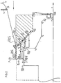
- FIG. 1 there is shown a machine tool 1 supporting a workpiece 2.
- This machine tool comprises a tool carrier turret not shown.
- the various control members and the various sensors of this machine tool are connected by an electronic card 3 playing the role of axis coupler, which is connected to a bus 4.
- the card 3 has the function of ensuring the connection with sensors that read the position of the moving parts of the machine and control their speed of movement.
- Bus 4 is connected to a microprocessor 5 and to a set of memories 7-8-9, respectively comprising at least one RAM memory R.A.M. 7, an E.E.P.R.O.M. 8, and a R.E.P.R.O.M. 9.
- R.E.P.R.O.M. contains the codes, instructions and software for operating the device.
- E.E.P.R.O.M. contains the machine parameters, that is to say the definitions of the movements of the moving parts and of the servo gains.
- R.A.M. may consist of a set of random access memories and contains all the rest of the information necessary for the operation of the device, as will be explained below.
- the bus 4 is also connected to a card 6 playing the role of serial coupler and ensuring the transmission and the shaping of the signals which pass through the bus and are intended for an assembly 10 comprising a control keyboard and a display member.
- a second serial coupling card provides the link between the bus and a ribbon reader 12.
- the programmer enters into the device, either from the tape reader 12, or from the keyboard with control on the display device, the program which defines the finished profile of the part and its raw profile, as well as the indications which specify whether the roughing must be carried out parallel to the X axis, or parallel to the Z axis.
- the program will specify the allowance along the X and Z axis which must be accepted so that, at the end of machining, we can call up a part finishing cycle which will finish it with precision and desired finish.
- the program will also specify the cutting depth, the tool feed speed and the spindle speed.
- the finished profile may include two grooves F and G.
- the program will be located in an area of the R.A.M. 7.
- This operation is only carried out when there are several grooves successively included in one another.
- the microprocessor searches, in the values X'i preceding the value X * i + 1 , that which is equal to or greater than X * i + 1 .
- X'i corresponds to X P9 .
- the microprocessor then takes the portion of the program between the two addresses N32 and N36, where the values X P13 and X P9 are located respectively and stores this portion of program in a second area 72 of the RAM 7 RAM, area that the we will call “storage area for finished throat profile programs”.
- the finished profile roughing program no longer includes instructions N33 to N36 included.
- the microprocessor 5 will search in the content of the area 71 if there are Z * n + 1 such that Z * n + y ⁇ Z n .
- the microprocessor searches for the largest among the Z n * preceding a Z * n + 1 . In the example, it is Zp 3 at address N42. Finally, the microprocessor searches for the address where there is a Zn which is greater than or equal to Zn * . In the example, it will be N38.
- the microprocessor eliminates from the program of the finished profile the instructions included between the addresses N39 to N42 inclusive, and will store these instructions in the RAM area 7.
- the new finished profile program cleared of the concave portions, is stored in a third area 73 of the RAM. Once this operation has been carried out, the microprocessor will start from the new finished profile defined in the memory area 73, profile no longer comprising concave portions. and perform a translation along X of a value I, and along Z of a value K of the new finite profile, by adding a value K to each memory word containing a value Z, and a value I to each memory word containing a value X.
- the microprocessor calculates the coordinates of the representative points of the tool movement and transmits the values representative of the movements to be made to the coupler 3 to control the machine.
- the microprocessor will determine, thanks to its software, the last point preceding a variation of ⁇ X on the raw profile and order the displacement of the tool from the rest position X o , Z 0 , up to point B ( Figure 2).
- the microprocessor calculates the coordinates of the point X 1 , Z 1 along the straight line BC, for which the variation of ⁇ X is equal to the depth of pass set by the program.
- the microprocessor orders the displacement of the tool from point B to the point of coordinates X 1 , Z 1 , then from point X 1 , Z 1 to point X 1 , Z a + K.
- the tool then goes up to X A + I; Z a + K and goes, passing through point B, to the point of coordinates X 2 , Z 2 which corresponds to a new ⁇ X equal to the depth of pass P.
- the tool then moves from point X 2 , Z 2 at point X 2 , Z P2 + K, then goes back to point X P2 + I, Zp 2 + K to start again at point X P2 + I, Z a + K.
- the tool finally goes back to X 1 , Z a + K to return to the raw profile and come, along the line BC, position in X 3 Z 3 .
- the cycles continue thus until the tool reaches the point of coordinates X e , Z e .
- the tool starting from the positions evaluated by the microprocessor from the raw profile data, loses less time in unnecessary movements and is always cutting, except in the release and return phases of the tool at the next point of the raw profile not yet machined.
- the conventional method which consists in using the image of a cylindrical bar as the raw profile, the time required to move the tool in the hatched area is saved.
- These displacements are especially penalizing as regards the displacements of the tool carried out in the direction of pass, because, in the phases of release and return of the tool, one can use a greater speed of displacement.
- the programmer in the execution program stored in memory 9, writes two instructions G65 first controlling the machining of the groove portion on the right of a descent line, then the machining of the groove portion to the left of the descent line.
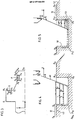
- the microprocessor uses the groove profiles of memory 72 to carry out the calculations thanks to the software and to control the displacements, as shown in FIG. 4, bringing the tool having the leading edge on the left, to descend along the right. 40 and take a pass of depth P until it meets the translated profile 41.
- the tool emerges from the part, returns along the straight line 40, performs a second dive and a second pass 2.
- the process is repeated, and the calculations are carried out as indicated above, until the tool has removed all the material not belonging to the finished profile, increased by an additional thickness as shown in 50, figure 5.
- the microprocessor controls a tool change and performs the groove roughing cycle on the right with the tool having the leading edge on the right.
- the process takes place as before; only the direction of the pass has changed, and the microprocessor uses the finished translated profile 51 and the descent line to calculate the displacements and the commands.
- the finished profile is represented by 52 and the hatching 53 represents the throat portions remaining to be removed.
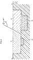
- Figures 4 and 5 relate to simple grooves. If a complex concavity, such as that shown in FIG. 6, has to be treated, the programmer will program the machining of the profile of this concavity. The microprocessor will start by processing the profile to the left of the descent line, formed by the concavities 61 and 63 and will eliminate the concavities included in this profile. It therefore eliminates the concavity 63 and machines the profile 61.
- the device processes the right part, consisting of the profiles 62 and 64, and machines the profile 62 without taking account of the concavity 64. Thereafter, each of the simple concavities 63, 64 will be treated as explained above. .
- the left profile is machined in one go consisting of 61 and the part of 63 located to the left of the descent line; then, the straight profile formed by 62 and the part of 63 located to the right of the descent line, and in this case, the machining of 64 (simple concavity) should be programmed separately as indicated above.
Landscapes
- Engineering & Computer Science (AREA)
- Physics & Mathematics (AREA)
- Manufacturing & Machinery (AREA)
- Human Computer Interaction (AREA)
- General Physics & Mathematics (AREA)
- Automation & Control Theory (AREA)
- Geometry (AREA)
- Numerical Control (AREA)
Description
- La présente invention concerne un procédé d'usinage d'un profil fini à partir d'un profil brut et le dispositif de mise en oeuvre du procédé.
- On connaît des procédés d'usinage d'un profil fini dans lesquels le profil brut est usiné suivant des déplacements parallèles au profil fini. En général, ces procédés ont pour inconvénient de faire varier la profondeur de passe ou l'épaisseur du copeau, donc de ne pas utiliser l'outil à son maximum de capacité.
- Il est également connu de partir d'un profil brut simulant une forme de barreau cylindrique et de l'usiner suivant une direction parallèle à l'axe de broche. Cet autre procédé a l'inconvénient, lorsque l'on utilise des profils bruts matricés ou sortant de fonderie et ayant un profil avoisinant le profil fini, de faire perdre du temps par des déplacements inutiles de l'outil entre le profil brut simulant un cylindre et le profil brut matricé.
- La présente invention a pour but principal d'éliminer les inconvénients de l'art antérieur, c'est-à-dire d'utiliser l'outil à sa capacité maximum et de limiter le plus possible les déplacements improductifs de l'outil.
- Ce résultat est atteint grâce à un procédé d'usinage d'un profil fini par une machine-outil à commande numérique caractérisé en ce qu'il comprend les étapes suivantes :
- 1) Introduction d'une description du profil fini, puis du profil brut, respectivement dans un premier et un deuxième moyens de mémorisation ;
- 2) Traitement de la description du profil fini pour supprimer, après analyse, les portions de profil présentant une concavité et rangement de la description des portions de profil présentant une concavité dans un troisième moyen de mémorisation ;
- 3) Rangement du profil fini « dit épuré», c'est-à-dire débarrassé des portions concaves, dans un quatrième moyen de mémorisation ;
- 4) Elaboration de l'ébauche du profil fini épuré par passes successives en déplaçant l'outil entre les coordonnées fournies par la mémoire du profil fini épuré et la mémoire du profil brut.
- Un autre but de l'invention est d'obtenir une capacité maximale de coupe lors de l'usinage du profil fini, et ce, même dans les parties concaves.
- Ce résultat supplémentaire est atteint grâce à un procédé caractérisé en ce que, lors de l'opération de tournage d'une concavité complexe, la commande numérique :
- a) récupère le profil d'une concavité rangée dans le troisième moyen de mémorisation et examine les portions de profil situées à droite et à gauche d'une droite de descente programmée ;
- b) élimine, des profils situés à droite ou à gauche de la droite de descente, les concavités incluses dans l'un des profils droit ou gauche, pour transformer la concavité complexe en concavité simple ;
- c) effectue l'opération d'usinage de la concavité simple ;
- d) réitère les opérations précédentes sur une autre concavité simple de la concavité complexe.
- Un troisième but de l'invention est la réalisation d'un dispositif permettant la mise en oeuvre du procédé de l'invention.
- Ce troisième résultat est obtenu au moyen d'un dispositif comprenant :
- - des moyens de délivrer, à un microprocesseur relié à un bus, un programme définissant le profil brut et le profil fini, ledit microprocesseur, après compilation, adressant lesdits profils brut et fini respectivement dans des premières mémoires vives ;
- - des secondes mémoires mortes, reliées au bus, comprenant respectivement les paramètres de la machine d'usinage à commander et un logiciel ;
- - des moyens de traiter le profil fini pour en ôter les concavités et élaborer un profil fini dit épuré ;
- - une troisième mémoire vive destinée à recevoir la description des parties concaves ;
- - une quatrième mémoire vive destinée à recevoir le profil fini dit épuré, c'est-à-dire ne comprenant plus de concavité,
- - des moyens d'assurer la liaison et la transmission des commandes entre le bus et la machine à commander.
- D'autres particularités et avantages de l'invention apparaîtront plus clairement à la lecture de la description ci-après, faite en se référant aux dessins annexés, dans lesquels :
- La figure 1 est une vue schématique de moyens permettant la mise en oeuvre du procédé d'usinage de l'invention ;
- La figure 2 représente les passes d'usinage de l'outil entre un profil brut et un profil fini selon le procédé d'usinage ;
- La figure 3 est une vue latérale d'un profil fini comportant des gorges
- Les figures 4 et 5 sont des vues en coupe d'une concavité simple ou gorge et des illustrations des étapes d'usinage de cette gorge ; et
- La figure 6 est une vue en coupe d'une concavité complexe.
- A la figure 1, on a représenté une machine-outil 1 supportant une pièce à usiner 2. Cette machine-outil comporte une tourelle porte-outil non représentée. Les différents organes de commande et les différents capteurs de cette machine-outil sont reliés par une carte électronique 3 jouant le rôle de coupleur d'axes, qui est branchée sur un bus 4. La carte 3 a pour fonction d'assurer la liaison avec les capteurs qui lisent la position des parties mobiles de la machine et de piloter leur vitesse de déplacement.
- Le bus 4 est relié à un microprocesseur 5 et à un ensemble de mémoires 7-8-9, comprenant respectivement au moins une mémoire vive R.A.M. 7, une mémoire E.E.P.R.O.M. 8, et une mémoire R.E.P.R.O.M. 9. La mémoire R.E.P.R.O.M. contient les codes, des instructions et le logiciel permettant le fonctionnement du dispositif.
- La mémoire E.E.P.R.O.M. contient les paramètres de la machine, c'est-à-dire les définitions des courses des organes mobiles et des gains d'asservissement.
- La mémoire R.A.M. peut être constituée d'un ensemble de mémoires vives et contient tout le reste des informations nécessaires au fonctionnement du dispositif, comme on l'expliquera dans la suite.
- Le bus 4 est également relié à une carte 6 jouant le rôle de coupleur série et assurant la transmission et la mise en forme des signaux qui transitent par le bus et sont destinés à un ensemble 10 comportant un clavier de commande et un organe de visualisation.
- Une deuxième carte de couplage série assure la liaison entre le bus et un lecteur de ruban 12.
- Le procédé d'usinage d'une ébauche est mis en oeuvre au moyen du dispositif décrit en se référant à la figure 1.
- Lorsqu'on veut par exemple, usiner la pièce 2 suivant un profil fini représenté par le tracé P1 à P7 de la figure 2, et que la pièce 2 a été obtenue par exemple en sortie de fonderie ou de matriçage avec un profil brut défini par les points A, B, C, D de la figure 2, le programmeur fait entrer dans le dispositif, soit à partir du lecteur de ruban 12, soit à partir du clavier avec contrôle sur le dispositif de visualisation, le programme qui définit le profil fini de la pièce et son profil brut, ainsi que les indications qui précisent si l'ébauche doit s'effectuer parallèlement à l'axe X, ou parallèlement à l'axe Z.
- De même, dans ses instructions, le programme précisera la surépaisseur suivant l'axe X et Z qui devra être admise pour que, en fin d'usinage, on puisse appeler un cycle de finition de la pièce qui la terminera avec la précision et la finition souhaitées.
- Le programme précisera aussi la profondeur de passe, la vitesse d'avance de l'outil et la vitesse de broche.
- Ces précisions seront définies dans le format explicité ci-après :

- Np1 à Np7: définition du profil fini : ébauche de Np1 vers NP7, l'ordre des séquences donnant le sens de l'usinage.
- XA ZA : coordonnées d'arrêt pour les premières passes d'ébauche.
- l, K : surépaisseur en X et Z.
- P ou R : profondeur de passe :
- P ébauche longitudinale
- R ébauche transversale
- F - S : vitesse d'avance et vitesse de broche.
- P ou R, F, S peuvent être modifiés en cours d'ébauche.
- Un exemple de programmation permettant de définir les profils brut et fini de la figure 2 est donné ci-dessous : Programmation
- N10 G Xo Zo : Initialisation en X et Z pour début de l'ébauche.
- N20 G79 N100 : Saut à la séquence d'appel du cycle d'ébauche

- N100 G64 N90 N30 XA ZA I K P F S Zone d'ébauche

- N160 G80 X Z : Fin du programme d'ébauche (dégagement)
- N170 G77 N30 N90 G41 T D F S : Exécution de la finition
- Cet exemple ne comporte pas de gorge ; toutefois, dans le cas représenté à la figure 3, le profil fini peut comporter deux gorges F et G.
- Dans ce cas, le programmeur modifiera en conséquence son programme de profil fini.
- Le programme ci-dessous correspond à celui écrit par le programmeur dans le cas d'un profil conforme à celui de la figure 3 :
- N10 GX0 Zo
- N20 G79 N100
- N30 GI XP15
- N31 XP14
- N32 XP13 ZP13
- N33 ZP12
- N34 XP11 BR11 BR11 = rayon du congé
- N35 ZP10 BR10 BR10 = rayon du congé
- N36 XP9
- N37 ZP8
- N38 XP7 ZP7,
- N39 XP6
- N40 Xp5 Zp 5
- N41 Xp 4
- N42 Xp3 Zp 3
- N43 Xp 2
- N44 ZP1
- Le programme sera rangé dans une zone de la R.A.M. 7.
- On supposera que le programme du profil brut est rangé dans la zone 70 de la R.A.M. ; le dispositif va alors fonctionner de la façon suivante lors du traitement d'un cycle d'ébauche :
- Une fois que le profil fini a été introduit dans la zone 71 de la R.A.M. 7, le microprocesseur effectue une recherche des parties concaves du profil fini, en recherchant d'abord les gorges telles que F (figure 3). Pour cela, le microprocesseur, grâce au logiciel inclus dans la mémoire 9, compare les valeurs des mots contenus dans les mémoires et cherche s'il existe des X*i+1 tels que

- Dans l'exemple, ce sera XP13.
- Ensuite, il recherche le plus grand des X*i+1 satisfaisant la relation (1). Dans l'exemple, ce sera XP13.
- Cette opération est seulement effectuée lorsque l'on a plusieurs gorges incluses successivement l'une dans l'autre.
- Enfin, le microprocesseur cherche, dans les valeurs X'i précédant la valeur X*i+1, celle qui est égale ou supérieure à X*i+1. Dans l'exemple considéré, X'i correspond à XP9.
- Le microprocesseur prend alors la portion du programme comprise entre les deux adresses N32 et N36, où se trouvent respectivement les valeurs XP13 et XP9 et rangé cette portion de programme dans une deuxième zone 72 de la mémoire vive 7 R.A.M., zone que l'on appellera « zone de stockage des programmes de profil fini de gorge ».
- Après cette opération, le programme de l'ébauche du profil fini ne comprend plus les instructions N33 à N36 incluse. De même, pour les gorges dont la concavité est orientée selon Z, le microprocesseur 5 va rechercher dans le contenu de la zone 71 s'il existe des Z*n+1 tel que Z* n+y < Zn.
- Dans l'exemple considéré, il s'agit de ZP5.
- Ensuite, le microprocesseur recherche le plus grand parmi les Zn * précédant un Z*n+1. Dans l'exemple, il s'agit de Zp3 à l'adresse N42. Enfin, le microprocesseur recherche l'adresse où se trouve un Zn qui soit supérieur ou égal à Zn*. Dans l'exemple, ce sera N38.
- Le microprocesseur élimine du programme du profil fini les instructions comprises entre les adresses N39 à N42 incluse, et va ranger ces instructions dans la zone de la mémoire vive 7.
- Le nouveau programme de profil fini, débarrassé des portions concaves, est rangé dans une troisième zone 73 de la R.A.M. Une fois cette opération réalisée, le microprocesseur va partir du nouveau profil fini défini dans la zone mémoire 73, profil ne comportant plus de parties concaves et effectuer une translation suivant X d'une valeur I, et suivant Z d'une valeur K du nouveau profil fini, en ajoutant une valeur K à chaque mot mémoire contenant une valeur Z, et une valeur I à chaque mot mémoire contenant une valeur X. Enfin, partant de cette table définissant le nouveau profil fini translaté, rangée dans une quatrième zone 74, ou bien élaborée au fur et à mesure des besoins du microprocesseur à partir de la table 73, le microprocesseur calcule les coordonnées des points représentatifs du déplacement de l'outil et transmet les valeurs représentatives des déplacements à effectuer au coupleur 3 pour asservir la machine. Dans le cas d'une ébauche réalisée parallèlement à l'axe Z, le microprocesseur va déterminer, grâce à son logiciel, le dernier point précédant une variation de ΔX sur le profil brut et ordonner le déplacement de l'outil de la position de repos Xo, Z0, jusqu'au point B (figure 2).
- Le microprocesseur calcule les coordonnées du point X1, Z1 le long de la droite BC, pour lequel la variation du △X est égale à la profondeur de passe fixée par le programme.
- Le microprocesseur ordonne le déplacement de l'outil du point B au point de coordonnées X1, Z1, puis du point X1, Z1 au point X1, Za + K.
- L'outil monte ensuite jusqu'à XA + I ; Za + K et va, en passant par le point B, au point de coordonnées X2, Z2 qui correspond à un nouveau △X égal à la profondeur de passe P. L'outil se déplace ensuite du point X2, Z2 au point X2, ZP2 + K, puis remonte vers le point XP2 + I, Zp2 + K pour repartir vers le point XP2 + I, Za + K. L'outil remonte enfin en X1, Za + K pour retourner sur le profil brut et venir, le long de la droite BC, se positionner en X3 Z3. Les cycles se poursuivent ainsi jusqu'à ce que l'outil atteigne le point de coordonnées Xe, Ze.
- On comprend aisément que l'outil, partant des positions évaluées par le microprocesseur à partir des données du profil brut, perd moins de temps en déplacements inutiles et est toujours en train de couper, sauf dans les phases de dégagement et de retour de l'outil, au point suivant du profil brut non encore usiné. Par rapport au procédé classique qui consiste à utiliser comme profil brut l'image d'un barreau cylindrique, on gagne le temps des déplacements de l'outil dans la zone hachurée. Ces déplacements sont surtout pénalisants en ce qui concerne les déplacements de l'outil effectués dans le sens de passe, car, dans les phases de dégagement et de retour de l'outil, on peut utiliser une plus grande vitesse de déplacement.
- D'autre part, comme le profil fini est exécuté sans les gorges, on peut utiliser des outils 13 du type représenté à la figure 2, avec un seul bord de coupe 14 orienté du côté du sens de passe.
- Ces outils ont une résistance et une capacité de coupe plus grandes que celles des outils présentant deux surfaces de coupe et permettent donc d'effectuer des passes de profondeur plus grande, donc une ébauche plus rapide.
- Ensuite, dans le cas où l'ébauche du profil fini doit comporter des gorges, le programmeur, dans le programme d'exécution rangé dans la mémoire 9, écrit deux instructions G65 commandant d'abord l'usinage de la portion de gorge à droite d'une droite de descente, puis l'usinage de la portion de gorge à gauche de la droite de descente.
- Le format de l'instruction de cycle de gorge est le suivant : Format
- G65 N1 N2 A P ou R X ou Z 1 K F S
- N1 et N2 sont deux séquences du profil fini de part et d'autre de la gorge.
- A est l'angle de pénétration pour l'usinage (la pénétration s'effectue à la vitesse F programmée).
- P ou R sont les profondeurs de passe suivant X ou Z.
- F, S sont les vitesses d'avance et de broche.
- L'ordre des séquences N1-N2 donne la partie devant être usinée :
- N1-N2 : usinage à gauche de la droite A.
- N2-N1 : usinage à droite de la droite A.
- Le programmeur ajoute donc, à la suite du programme d'ébauche du profil sans gorge, les instructions suivantes :
- N180 G65, P12-P9, A, P, ZP9, K, F, S.
- N190 : Instruction de changement d'outil
- N200 G65, P9-P12, A, P, ZP12 K, F, S.
- Le microprocesseur utilise les profils de gorges de la mémoire 72 pour exécuter les calculs grâce au logiciel et commander les déplacements, comme représenté à la figure 4, amenant l'outil ayant le bord d'attaque à gauche, à descendre le long de la droite 40 et à prendre une passe de profondeur P jusqu'à la rencontre avec le profil translaté 41.
- Ensuite, l'outil se dégage de la pièce, revient le long de la droite 40, effectue une seconde plongée et une deuxième passe 2. Le procédé se réitère, et les calculs se font comme indiqué précédemment, jusqu'à ce que l'outil ait enlevé toute la matière n'appartenant pas au profil fini, augmenté d'une surépaisseur comme représenté en 50, figure 5.
- Ensuite, le microprocesseur commande un changement d'outil et exécute le cycle d'ébauche de gorge à droite avec l'outil ayant le bord d'attaque à droite.
- Le processus se déroule comme précédemment ; seul le sens de passe a changé, et le microprocesseur utilise le profil fini translaté 51 et la droite de descente pour calculer les déplacements et les commandes.
- Le profil fini est représenté par 52 et les hachures 53 représentent les portions de gorge restant à enlever.
- La description a été faite par rapport à une gorge dont la concavité est orientée suivant l'axe X ; mais le procédé reste identique pour une gorge dont la concavité est orientée suivant l'axe de Z.
- Les exemples des figures 4 et 5 concernent des gorges simples. Si l'on doit traiter une concavité complexe, telle que celle représentée à la figure 6, le programmeur va programmer l'usinage du profil de cette concavité. Le microprocesseur va commencer par traiter le profil à gauche de la droite de descente, constitué par les concavités 61 et 63 et va éliminer les concavités incluses dans ce profil. Il élimine donc la concavité 63 et usine le profil 61.
- Ensuite, le dispositif traite la partie droite, constituée des profils 62 et 64, et usine le profil 62 sans tenir compte de la concavité 64. Par la suite, chacune des concavités simples 63, 64 sera traitée comme on l'a expliqué plus haut.
- Il est bien évident que, si la droite de descente tombe dans la concavité 63 par exemple, on usine alors en une seule fois le profil gauche constitué par 61 et la partie de 63 située à gauche de la droite de descente ; puis, le profil droit constitué par 62 et la partie de 63 située à droite de la droite de descente, et dans ce cas, l'usinage de 64 (concavité simple) devrait être programmé séparément comme on l'a indiqué plus haut.
- Il est bien évident que toute modification à la portée de l'homme de l'art fait également partie de l'invention.
Claims (8)
Priority Applications (4)
| Application Number | Priority Date | Filing Date | Title |
|---|---|---|---|
| FR8305921A FR2544242B1 (fr) | 1983-04-12 | 1983-04-12 | Procede d'usinage d'un profil fini et dispositif de mise en oeuvre du procede |
| DE8484402056T DE3478823D1 (en) | 1984-10-12 | 1984-10-12 | Process for manufacturing a finished profile, and device for carrying it out |
| EP84402056A EP0177655B1 (fr) | 1983-04-12 | 1984-10-12 | Procédé d'usinage d'un profil fini et dispositif de mise en oeuvre du procédé |
| HK28690A HK28690A (en) | 1984-10-12 | 1990-04-12 | Process for manufacturing a finished profile, and device for carrying it out |
Applications Claiming Priority (2)
| Application Number | Priority Date | Filing Date | Title |
|---|---|---|---|
| FR8305921A FR2544242B1 (fr) | 1983-04-12 | 1983-04-12 | Procede d'usinage d'un profil fini et dispositif de mise en oeuvre du procede |
| EP84402056A EP0177655B1 (fr) | 1983-04-12 | 1984-10-12 | Procédé d'usinage d'un profil fini et dispositif de mise en oeuvre du procédé |
Publications (2)
| Publication Number | Publication Date |
|---|---|
| EP0177655A1 EP0177655A1 (fr) | 1986-04-16 |
| EP0177655B1 true EP0177655B1 (fr) | 1989-06-28 |
Family
ID=26095275
Family Applications (1)
| Application Number | Title | Priority Date | Filing Date |
|---|---|---|---|
| EP84402056A Expired EP0177655B1 (fr) | 1983-04-12 | 1984-10-12 | Procédé d'usinage d'un profil fini et dispositif de mise en oeuvre du procédé |
Country Status (2)
| Country | Link |
|---|---|
| EP (1) | EP0177655B1 (fr) |
| FR (1) | FR2544242B1 (fr) |
Families Citing this family (4)
| Publication number | Priority date | Publication date | Assignee | Title |
|---|---|---|---|---|
| JPH0766290B2 (ja) * | 1986-06-26 | 1995-07-19 | 東芝機械株式会社 | 工具経路生成方法 |
| EP0310106A3 (fr) * | 1987-10-02 | 1989-05-24 | Mitsubishi Denki Kabushiki Kaisha | Méthode pour former des données de configuration pour un appareil d'usinage à C.N.C. |
| JPH0265945A (ja) * | 1988-08-31 | 1990-03-06 | Okuma Mach Works Ltd | 数値制御情報作成機能における加工方法の決定方式 |
| JPH05297926A (ja) * | 1992-04-22 | 1993-11-12 | Fanuc Ltd | 加工定義方法 |
Family Cites Families (3)
| Publication number | Priority date | Publication date | Assignee | Title |
|---|---|---|---|---|
| DE1199855B (de) * | 1965-09-02 | Darmstadt Dr.-Ing. W. de Beauclair | Elektronische Steuerung einer Werkzeugmaschine | |
| AU6339680A (en) * | 1979-10-02 | 1981-04-28 | Daihatsu Motor Co. Ltd. | Method of controlling numerical controlled machine tool |
| JPS58155101A (ja) * | 1982-03-11 | 1983-09-14 | Yamazaki Mazak Corp | 4軸数値制御旋盤 |
-
1983
- 1983-04-12 FR FR8305921A patent/FR2544242B1/fr not_active Expired
-
1984
- 1984-10-12 EP EP84402056A patent/EP0177655B1/fr not_active Expired
Also Published As
| Publication number | Publication date |
|---|---|
| EP0177655A1 (fr) | 1986-04-16 |
| FR2544242B1 (fr) | 1986-11-28 |
| FR2544242A1 (fr) | 1984-10-19 |
Similar Documents
| Publication | Publication Date | Title |
|---|---|---|
| FR2459110A1 (fr) | Machine-outil a commande numerique | |
| FR2522293A1 (fr) | Procede pour commander l'alignement des outils dans une machine-outil a commande numerique | |
| EP0841606A3 (fr) | Méthode d'usinage tridimensionnelle et milieu d'enregistrement stockant un programme de commande d'usinage tridimensionnelle | |
| US20200174442A1 (en) | Machining parameter adjustment system and machining parameter adjustment method | |
| EP0093955A2 (fr) | Appareil de commande pour une machine à meuler | |
| FR2588977A1 (fr) | Organe de commande numerique pour rectifieuse | |
| EP0177655B1 (fr) | Procédé d'usinage d'un profil fini et dispositif de mise en oeuvre du procédé | |
| JP2003256009A5 (fr) | ||
| US4703415A (en) | Method of approach in area cutting | |
| EP2510410B1 (fr) | Procede pour optimiser les conditions de travail d'un outil coupant | |
| FR2466798A1 (fr) | Procede de commande numerique d'une machine-outil | |
| EP0104542A1 (fr) | Méthode d'usinage à commande numérique | |
| EP0474603B1 (fr) | Procédé et dispositif de commande d'un ou de plusieurs axes dans une machine-outil | |
| CN120630859A (zh) | 数控机床控制方法、装置、计算机设备和存储介质 | |
| JP2724647B2 (ja) | 数値制御における送り速度制御方法 | |
| JP3827922B2 (ja) | 自動旋盤の制御装置 | |
| EP0819279B1 (fr) | Procede de saisie graphique d'application de traitement de signal | |
| WO1999013386A1 (fr) | Procede de generation d'un plan d'usinage de piece pour commande numerique de machine-outil | |
| JPH0338065B2 (fr) | ||
| FR2650771A1 (fr) | Procede permettant d'usiner une partie en coin dans une piece au moyen d'un appareil d'usinage par decharge electrique a commande numerique et dispositif de preparation d'un programme de commande pour cet appareil | |
| BE883839A (fr) | Machine-outil a commande numerique | |
| CN118123523A (zh) | 摆转控制方法、装置、机床及可读存储介质 | |
| CN120578118A (zh) | 一种规划位置路径的方法及刀库伺服 | |
| EP1760561B1 (fr) | Procédé de gestion d'informations pour la programmation de la commande d'une machine-outil | |
| JPH0513785B2 (fr) |
Legal Events
| Date | Code | Title | Description |
|---|---|---|---|
| PUAI | Public reference made under article 153(3) epc to a published international application that has entered the european phase |
Free format text: ORIGINAL CODE: 0009012 |
|
| 17P | Request for examination filed |
Effective date: 19841016 |
|
| AK | Designated contracting states |
Kind code of ref document: A1 Designated state(s): CH DE GB IT LI |
|
| 17Q | First examination report despatched |
Effective date: 19880115 |
|
| GRAA | (expected) grant |
Free format text: ORIGINAL CODE: 0009210 |
|
| AK | Designated contracting states |
Kind code of ref document: B1 Designated state(s): CH DE GB IT LI |
|
| GBT | Gb: translation of ep patent filed (gb section 77(6)(a)/1977) | ||
| ITF | It: translation for a ep patent filed | ||
| REF | Corresponds to: |
Ref document number: 3478823 Country of ref document: DE Date of ref document: 19890803 |
|
| PLBE | No opposition filed within time limit |
Free format text: ORIGINAL CODE: 0009261 |
|
| STAA | Information on the status of an ep patent application or granted ep patent |
Free format text: STATUS: NO OPPOSITION FILED WITHIN TIME LIMIT |
|
| 26N | No opposition filed | ||
| ITTA | It: last paid annual fee | ||
| PGFP | Annual fee paid to national office [announced via postgrant information from national office to epo] |
Ref country code: CH Payment date: 19950928 Year of fee payment: 12 |
|
| PGFP | Annual fee paid to national office [announced via postgrant information from national office to epo] |
Ref country code: GB Payment date: 19951009 Year of fee payment: 12 |
|
| PGFP | Annual fee paid to national office [announced via postgrant information from national office to epo] |
Ref country code: DE Payment date: 19951128 Year of fee payment: 12 |
|
| PG25 | Lapsed in a contracting state [announced via postgrant information from national office to epo] |
Ref country code: GB Effective date: 19961012 |
|
| PG25 | Lapsed in a contracting state [announced via postgrant information from national office to epo] |
Ref country code: LI Effective date: 19961031 Ref country code: CH Effective date: 19961031 |
|
| GBPC | Gb: european patent ceased through non-payment of renewal fee |
Effective date: 19961012 |
|
| REG | Reference to a national code |
Ref country code: CH Ref legal event code: PL |
|
| PG25 | Lapsed in a contracting state [announced via postgrant information from national office to epo] |
Ref country code: DE Effective date: 19970701 |