EP0177788A2 - Dispositif pour mesurer la pression de gonflage pour la surveillance continue des pneumatiques de véhicules automobiles - Google Patents
Dispositif pour mesurer la pression de gonflage pour la surveillance continue des pneumatiques de véhicules automobiles Download PDFInfo
- Publication number
- EP0177788A2 EP0177788A2 EP85111465A EP85111465A EP0177788A2 EP 0177788 A2 EP0177788 A2 EP 0177788A2 EP 85111465 A EP85111465 A EP 85111465A EP 85111465 A EP85111465 A EP 85111465A EP 0177788 A2 EP0177788 A2 EP 0177788A2
- Authority
- EP
- European Patent Office
- Prior art keywords
- pressure
- membrane
- pressure measuring
- cell
- measuring device
- Prior art date
- Legal status (The legal status is an assumption and is not a legal conclusion. Google has not performed a legal analysis and makes no representation as to the accuracy of the status listed.)
- Granted
Links
- 239000012528 membrane Substances 0.000 claims abstract description 42
- 238000012544 monitoring process Methods 0.000 claims abstract description 9
- 230000002093 peripheral effect Effects 0.000 claims description 12
- 238000007789 sealing Methods 0.000 claims description 5
- 230000005291 magnetic effect Effects 0.000 abstract description 8
- 239000002775 capsule Substances 0.000 abstract 4
- 210000004379 membrane Anatomy 0.000 description 34
- BGPVFRJUHWVFKM-UHFFFAOYSA-N N1=C2C=CC=CC2=[N+]([O-])C1(CC1)CCC21N=C1C=CC=CC1=[N+]2[O-] Chemical compound N1=C2C=CC=CC2=[N+]([O-])C1(CC1)CCC21N=C1C=CC=CC1=[N+]2[O-] BGPVFRJUHWVFKM-UHFFFAOYSA-N 0.000 description 3
- 230000008859 change Effects 0.000 description 3
- 230000006870 function Effects 0.000 description 3
- 238000012806 monitoring device Methods 0.000 description 3
- 230000005540 biological transmission Effects 0.000 description 2
- 238000009434 installation Methods 0.000 description 2
- 238000005259 measurement Methods 0.000 description 2
- 230000008901 benefit Effects 0.000 description 1
- 238000009530 blood pressure measurement Methods 0.000 description 1
- 230000005347 demagnetization Effects 0.000 description 1
- 230000001419 dependent effect Effects 0.000 description 1
- 238000013461 design Methods 0.000 description 1
- 238000011161 development Methods 0.000 description 1
- 230000018109 developmental process Effects 0.000 description 1
- 238000010586 diagram Methods 0.000 description 1
- 230000000694 effects Effects 0.000 description 1
- 239000000806 elastomer Substances 0.000 description 1
- 229920001971 elastomer Polymers 0.000 description 1
- 238000011156 evaluation Methods 0.000 description 1
- 239000003302 ferromagnetic material Substances 0.000 description 1
- 230000004907 flux Effects 0.000 description 1
- 239000007789 gas Substances 0.000 description 1
- 239000001307 helium Substances 0.000 description 1
- 229910052734 helium Inorganic materials 0.000 description 1
- SWQJXJOGLNCZEY-UHFFFAOYSA-N helium atom Chemical compound [He] SWQJXJOGLNCZEY-UHFFFAOYSA-N 0.000 description 1
- 230000006698 induction Effects 0.000 description 1
- 230000007774 longterm Effects 0.000 description 1
- 238000004519 manufacturing process Methods 0.000 description 1
- 239000000463 material Substances 0.000 description 1
- 238000000034 method Methods 0.000 description 1
- 238000003825 pressing Methods 0.000 description 1
- 230000008569 process Effects 0.000 description 1
- 238000012545 processing Methods 0.000 description 1
- 239000012858 resilient material Substances 0.000 description 1
- 230000035945 sensitivity Effects 0.000 description 1
- 230000011664 signaling Effects 0.000 description 1
- 229910001220 stainless steel Inorganic materials 0.000 description 1
- 239000010935 stainless steel Substances 0.000 description 1
- 238000003466 welding Methods 0.000 description 1
Images

Classifications
-
- B—PERFORMING OPERATIONS; TRANSPORTING
- B60—VEHICLES IN GENERAL
- B60C—VEHICLE TYRES; TYRE INFLATION; TYRE CHANGING; CONNECTING VALVES TO INFLATABLE ELASTIC BODIES IN GENERAL; DEVICES OR ARRANGEMENTS RELATED TO TYRES
- B60C23/00—Devices for measuring, signalling, controlling, or distributing tyre pressure or temperature, specially adapted for mounting on vehicles; Arrangement of tyre inflating devices on vehicles, e.g. of pumps or of tanks; Tyre cooling arrangements
- B60C23/02—Signalling devices actuated by tyre pressure
- B60C23/04—Signalling devices actuated by tyre pressure mounted on the wheel or tyre
- B60C23/0408—Signalling devices actuated by tyre pressure mounted on the wheel or tyre transmitting the signals by non-mechanical means from the wheel or tyre to a vehicle body mounted receiver
- B60C23/0422—Signalling devices actuated by tyre pressure mounted on the wheel or tyre transmitting the signals by non-mechanical means from the wheel or tyre to a vehicle body mounted receiver characterised by the type of signal transmission means
- B60C23/0425—Means comprising permanent magnets, e.g. Hall-effect or Reed-switches
Definitions
- the invention relates to a pressure measuring device for the continuous monitoring of the air pressure in vehicle tires, in which a membrane and a magnet which can be moved with it is inserted in a pressure measuring cell consisting of a lower part with a seal which can be fastened thereon and which responds to changes in the tire pressure and transmits these to a terminal .
- Tire monitoring devices in which a magnet is moved over membranes or pressure measuring cells depending on the prevailing tire pressure or the magnetic field is changed in another way have been proposed in numerous embodiments.
- a warning system for low tire pressure in which a magnet is provided with first and second pole faces in order to form a closed magnetic flux when the magnet is in the normal position.
- the device has a low-pressure air switch in a chamber system provided with a plurality of valves and an air bellows providing the reference pressure.
- the low pressure air switch is attached to the rim of the vehicle tire and extends into the tire.
- a piston sealed by an O-ring is actuated, which releases the bellows movement.
- the magnet is moved from the normal position to an extended position.
- the external magnetic field thus generated is sensed by a stationary scanner to generate a signal.
- DE-OS 28 48 942 describes a similar monitoring system with magnetic signaling, which is mounted inside the rim and thus in the air space of the vehicle tire.
- the device must therefore be fitted before the tire is fitted and adjusted by loading it with helium gas.
- This monitoring system also consists of numerous components, such as an expandable bellows and the associated magnetic unit with permanent magnets and pole piece, a plate made of ferromagnetic material.
- the fact that the device is no longer accessible after tire installation is particularly disadvantageous.
- the magnet is moved in the radial direction to the vehicle wheel.
- a tire pressure meter with a magnetic transmission device for the measured value of vehicle tires is known.
- This pressure meter consists of a D ruck cell with a corrugated stainless steel membrane on which a hole in the rim of the prevailing tire pressure acts.
- the corrugated membrane carries a magnet that is moved radially to the wheel depending on the tire pressure.
- a reference magnet is provided which rotates with the wheel rotation but does not execute any radial movement. Each magnet rotates both magnets past an induction coil and the induced voltages are processed electrically so that they can be compared. Any voltage differences indicate a drop in pressure in the monitored rows.
- the object of the invention is to provide a pressure measuring device of the type mentioned, which can be produced from a few individual parts in a simple, compact design and is easy to mount on the rim flange of a vehicle tire, can be easily adapted to different areas of application with different pressure ratios and functions reliably.
- a pressure measuring device of the type mentioned that the membrane consists of a flachkonisch extending from a circular peripheral edge inwardly membrane member having a central öff - having voltage and pulled on the outside of this cylindrical to and sealed to the bottom of this cylindrical extension is the membrane is inserted spanning the interior of the pressure cell and is seated with its peripheral edge on an inward shoulder on the free edge of the lower part of the pressure cell and is tightly held here by the cover screwed onto the lower part, in which a permanent magnet is inserted in the cylindrical extension of the membrane and the cover has a connection piece which can be connected to a valve of a vehicle tire, and that the pressure measuring cell is assigned a magnetoresistive sensor which interacts with a terminal.
- the pressure transducer according to the invention with a linear characteristic curve and the use of a linear magnet-sensitive sensor based on the magnetoresistive effect enables a simple circuit arrangement that conveys a status indicator of the vehicle tire over a relatively large distance of more than 2 cm without contact.
- the pressure cell can be built in very small dimensions and with low weight.
- the linear path change of the membrane depends on the tire pressure. It is made of a material that is sufficiently sensitive to respond to changes in nominal or target pressure.
- the load cell can be easily adapted to different areas of application with different pressure conditions.
- the pressure cell is divided into two chambers by the membrane.
- the desired set pressure is first applied to one chamber, then mounted on the rim flange of a vehicle tire and connected to a valve of the tire, thereby doing so Pressure balance is established in the chambers.
- the installation of this handy pressure cell on the rim flange is extremely simple and the advantage is that this small device is accessible from the outside at all times.
- a permanent magnet with high temperature stability and large coercive field strength is used, in which no demagnetization occurs.
- the few components that can be easily adapted to the requirements result in a safe monitoring device that can be easily mounted on vehicle tires. Naturally, this also applies to the sensor that interacts with the pressure cell to give the desired signal that indicates a change in tire pressure.
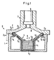
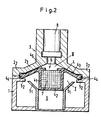
- the pressure transducer generally designated D, consists of a cylindrical lower part 1 and a cover 2, which can be placed tightly thereon, with connecting pieces 3 for connection to a valve of a vehicle tire (not shown).
- the membrane 4 consists of a cylindrical extension 4 1 with a closed bottom 4 2 . From the edge of the attachment 4 1 opposite the bottom 4 2 and delimiting an opening 6 there is a flat conical outward and upward directed membrane part 4 3 , the peripheral edge 4 4 of which sits on a shoulder 5 2 of the lower part 1 of the pressure cell D. This shoulder 5 2 is directed radially inward on the free edge of the lower part 1 facing the cover 2.
- the membrane 4 spans the interior of the pressure cell and is linearly movable.
- a seat adapted to the shape of the membrane 4 is expediently provided in the lower part 1 of the pressure cell D.
- This is formed by a cylindrical recess 5 for receiving the cylindrical diaphragm attachment 4 1 .
- From the free edge of the boundary of this recess 5 runs flat conically up to the shoulder 5 2 of the pressure cell D a seat 5 1 for the membrane 4.
- the cylindrical extension 4 1 of the membrane 4 is loosely inserted into the cylindrical recess 5 in the lower part of the pressure cell D and the flat conical membrane part 4 3 is loosely placed on the seat 5 1 .
- a permanent magnet 7 is inserted into the cylindrical extension 4 2 of the membrane 4 and is expediently held in position here by a rim 4 5 formed on the opening edge of the cylindrical extension 4 1 of the magnet 4 and directed radially inward and narrowing the opening 6.
- the lid 2 of the pressure cell D is sealingly connected to the lower part 1, and this connection can be made releasably, for example by screwing, or firmly, for example by welding. In the embodiment shown in Fig. 1, provision is made for releasable screwing. In the embodiment in FIG. 2, the cover 2 is fixed to the lower part 1, that is to say it cannot be detached.
- the cover 2 of the pressure cell D encompasses the upper edge region of the lower part 1 with a cylindrical ring 2 1 cylindrical ring 2 1 has an internal thread that is screwed onto a corresponding external thread on the lower part 1.
- the cover plate consists of a flat ring 2 2t which is directed inwards from the peripheral edge of the cylindrical ring 2 1 and which rests with its underside on the upper side of the shoulder 5 2 of the lower part 1 and on the peripheral edge 4 4 of the membrane 4.
- the peripheral edge 4 4 of the membrane which is preferably designed as a sealing lip, is held in a sealing manner between the shoulder 5 2 of the lower part 1 and the flat ring 2 2 of the cover 2.
- a flat conical lid part 2 3 extends, which is provided with a central opening which opens into the passage 8 of the connecting piece 3.
- the membrane 4 divides the interior of the pressure cell D into two separate chambers, namely into the chamber I in the lower part 1 and the chamber II in the cover 2.
- the chamber I is self-contained, while the chamber II via the passage 8 with the valve of the vehicle tire can be connected so that the pressure present in the vehicle tire is established in this chamber II.
- the pressure measuring cell D is assigned an electrical device which indicates the pressure conditions and which is stationary at a certain distance, which can be greater than 2 cm, parallel to the orbit of the pressure measuring cell D attached to the rim flange.
- This device consists of a sensor 9, which is preferably connected to a terminal 12 via amplifier 10 and a voltage-frequency converter 11.
- This terminal 12 is equipped with appropriate devices that enable the operator to determine the respective conditions of the pressure conditions in the vehicle tire.
- a memory 13 can thus be operated by pressing a pushbutton T be switched on.
- a comparator 14 is connected directly to the voltage-frequency converter 11 of the display device, while an alarm device 15 is connected downstream of this comparator 14.
- the transmitted signal is stored in memory 13. This reference value is then compared with values occurring due to pressure changes in the vehicle tire.
- the switching of the display device can be designed in different ways.
- the electrical variable that changes in chamber II when the pressure drops can be displayed continuously in order to trigger an alarm when a maximum permissible deviation is reached.
- the electrical signal is registered by the magnetoresistive sensor 9 each time the magnet 4 inserted in the pressure transducer D passes and passed on to the terminal 12.
- the signal size is independent of the frequency, i.e. the speed / time of the vehicle tire. When the tire comes to a standstill, there is naturally no measurement value determination or measurement value processing.
- a voltage-frequency converter 11 connected downstream of the amplifier 10 ensures interference-free transmission of the electrical signal to the terminal 12, irrespective of the length of the lines or the number of interposed plug contact connections.
- the frequencies which are set up are interrogated several times, compared with one another and only stored, counted, compared with the reference value and displayed when several measured values match in the terminal.
- a microprocessor is expediently used in the terminal for a large number of tires to be monitored.
- Adequate and secure monitoring is ensured if the terminal is set up for the following functions: querying the individual measuring points and storing them with assignment during the calibration process, querying the individual measuring points in a regularly recurring cycle, comparing the measured values with the stored values;
- the easy-to-assemble, extremely small pressure measuring cell which consists of a few components, and the indicator circle assigned to it work flawlessly and allow pressure changes in vehicle tires to be recognized at an early stage and thus prevent major damage.
Landscapes
- Engineering & Computer Science (AREA)
- Mechanical Engineering (AREA)
- Measuring Fluid Pressure (AREA)
Priority Applications (1)
| Application Number | Priority Date | Filing Date | Title |
|---|---|---|---|
| AT85111465T ATE58504T1 (de) | 1984-10-05 | 1985-09-11 | Druckmessvorrichtung zur kontinuierlichen ueberwachung des luftdruckes in fahrzeugreifen. |
Applications Claiming Priority (2)
| Application Number | Priority Date | Filing Date | Title |
|---|---|---|---|
| DE19843436493 DE3436493A1 (de) | 1984-10-05 | 1984-10-05 | Druckmessvorrichtung zur kontinuierlichen ueberwachung des luftdruckes in fahrzeugreifen |
| DE3436493 | 1984-10-05 |
Publications (3)
| Publication Number | Publication Date |
|---|---|
| EP0177788A2 true EP0177788A2 (fr) | 1986-04-16 |
| EP0177788A3 EP0177788A3 (en) | 1988-08-10 |
| EP0177788B1 EP0177788B1 (fr) | 1990-11-22 |
Family
ID=6247136
Family Applications (1)
| Application Number | Title | Priority Date | Filing Date |
|---|---|---|---|
| EP85111465A Expired - Lifetime EP0177788B1 (fr) | 1984-10-05 | 1985-09-11 | Dispositif pour mesurer la pression de gonflage pour la surveillance continue des pneumatiques de véhicules automobiles |
Country Status (5)
| Country | Link |
|---|---|
| US (1) | US4658644A (fr) |
| EP (1) | EP0177788B1 (fr) |
| JP (1) | JPS6191534A (fr) |
| AT (1) | ATE58504T1 (fr) |
| DE (2) | DE3436493A1 (fr) |
Families Citing this family (10)
| Publication number | Priority date | Publication date | Assignee | Title |
|---|---|---|---|---|
| US4924697A (en) * | 1988-01-11 | 1990-05-15 | Permanent Tire Gauge Company, Inc. | Tire-mounted air pressure gauge assembly |
| DE4016207A1 (de) * | 1990-05-19 | 1991-11-21 | Werner Seider | Druckmessvorrichtung zur ueberwachung des luftdruckes in fahrzeugreifen |
| GB2267759A (en) * | 1992-06-06 | 1993-12-15 | Martin Merry | Monitoring pressure of rotating tyre |
| DE4411709A1 (de) * | 1993-04-30 | 1994-11-03 | Auto Zubehoer Innovationen Ges | Reifendruckanzeige-Einrichtung |
| DE10039609A1 (de) * | 2000-08-09 | 2002-02-21 | Mannesmann Vdo Ag | Drucksensor |
| EP2000790B1 (fr) * | 2006-03-29 | 2012-09-12 | JMS Co., Ltd. | Dispositif de detection de la pression |
| GB0620246D0 (en) * | 2006-10-12 | 2006-11-22 | Univ Cambridge Tech | Extruded materials having capillary channels |
| US8584528B2 (en) * | 2011-10-19 | 2013-11-19 | Chia-Hsin Lee | Manometer with a pressure transforming device |
| WO2014073308A1 (fr) * | 2012-11-06 | 2014-05-15 | Nok株式会社 | Joint d'étanchéité d'embrayage |
| CN114377735B (zh) * | 2022-02-17 | 2025-08-15 | 美林美邦(厦门)生物科技有限公司 | 一种压差指示器 |
Family Cites Families (12)
| Publication number | Priority date | Publication date | Assignee | Title |
|---|---|---|---|---|
| DE635825C (de) * | 1937-06-03 | Fritz Schwien | Luftreifenueberwachungsvorrichtung | |
| DE836602C (de) * | 1948-12-30 | 1952-04-15 | Ilse Grigull Geb Munsch | Vorrichtung zur UEberwachung des Luftdruckes von Fahrzeugreifen |
| US2629086A (en) * | 1950-07-21 | 1953-02-17 | Ainsworth | Tire pressure responsive safety device |
| JPS5128616Y2 (fr) * | 1972-02-18 | 1976-07-19 | ||
| US3792677A (en) * | 1972-06-12 | 1974-02-19 | J Frost | Pressure indicator for pneumatic tire wheels |
| SU491056A1 (ru) * | 1973-08-06 | 1975-11-05 | Предприятие П/Я А-7626 | Датчик давлени |
| US4163208A (en) * | 1975-12-18 | 1979-07-31 | Merz Ernest J | Automatic wireless tire pressure monitoring system |
| DE2936213A1 (de) * | 1979-09-05 | 1981-03-19 | Günter 2211 Wirst Pruss | Vorrichtung zur pruefung und anzeige des reifendruckes |
| FR2471295A1 (fr) * | 1979-12-13 | 1981-06-19 | Schrader Sa | Dispositif comparateur de pression referencee pour pneu de vehicule avec affichage a distance |
| FR2497342A1 (fr) * | 1980-12-29 | 1982-07-02 | Labinal | Dispositif de mesure d'un parametre sur un organe rotatif, notamment pour la mesure de la pression d'un pneumatique sur une roue |
| DE3242291A1 (de) * | 1982-11-16 | 1984-05-17 | Moto Meter Ag, 7250 Leonberg | Vorrichtung zum messen des reifendrucks in luftreifen von fahrzeugen waehrend der fahrt |
| US4532390A (en) * | 1982-11-17 | 1985-07-30 | Signal Lux S.P.A. | Diaphragm pressure switch for controlling small pressure gradients |
-
1984
- 1984-10-05 DE DE19843436493 patent/DE3436493A1/de not_active Withdrawn
-
1985
- 1985-09-11 AT AT85111465T patent/ATE58504T1/de not_active IP Right Cessation
- 1985-09-11 DE DE8585111465T patent/DE3580644D1/de not_active Expired - Lifetime
- 1985-09-11 EP EP85111465A patent/EP0177788B1/fr not_active Expired - Lifetime
- 1985-09-25 US US06/779,931 patent/US4658644A/en not_active Expired - Fee Related
- 1985-10-03 JP JP60219314A patent/JPS6191534A/ja active Pending
Also Published As
| Publication number | Publication date |
|---|---|
| JPS6191534A (ja) | 1986-05-09 |
| EP0177788B1 (fr) | 1990-11-22 |
| DE3436493A1 (de) | 1986-04-10 |
| ATE58504T1 (de) | 1990-12-15 |
| US4658644A (en) | 1987-04-21 |
| EP0177788A3 (en) | 1988-08-10 |
| DE3580644D1 (de) | 1991-01-03 |
Similar Documents
| Publication | Publication Date | Title |
|---|---|---|
| EP0333708B1 (fr) | Detecteur de la pression de pneus de vehicules a moteur | |
| DE60015339T2 (de) | Drucküberwachungssystem | |
| EP0177788B1 (fr) | Dispositif pour mesurer la pression de gonflage pour la surveillance continue des pneumatiques de véhicules automobiles | |
| EP0248821B1 (fr) | Detecteur de la pression des pneus d'un vehicule | |
| EP0418495A1 (fr) | Installation de surveillance de la pression d'un pneumatique | |
| DE2102197C3 (de) | Drucksteuereinrichtung | |
| DE3545676C2 (de) | Druckmittelbetätigte, insbesondere pneumatische, Bremsanlage für Fahrzeuge | |
| DE2040786A1 (de) | Differenzdruck-Messumformer | |
| DE2855582A1 (de) | Druckschalter | |
| EP0946910A1 (fr) | Appareil de robinetterie pour la regulation du debit | |
| DE3246731A1 (de) | Einrichtung zum erfassen der position des kolbens eines arbeitszylinders | |
| EP0140066A1 (fr) | Dispositif pour la détection de forces, tensions resp. des accélérations de machines, appareils ou similaires | |
| DE2057973A1 (de) | Bremskraftregelanlage | |
| EP0263775A2 (fr) | Dispositif et méthode pour surveiller la pression d'un pneumatique d'automobile | |
| DE3740569C2 (de) | Differenzdruckgeber | |
| DE69400987T2 (de) | Reifendruck-Überwachungseinrichtung | |
| DE1461471A1 (de) | Filtergeraet mit elektrisch betaetigter Anzeigevorrichtung | |
| DE102006020438A1 (de) | Axialkraftaufnehmer | |
| GB1591690A (en) | Flowmeters | |
| WO1983004286A1 (fr) | Procede et dispositif pour la commande en fonction de la pression du fluide d'un moteur d'une turbomachine et support pour capteur de pression | |
| DE3730940A1 (de) | Vorrichtung zur anzeige der stellung des kolbens eines ventils | |
| US3367244A (en) | Pressure-sensitive devices | |
| DE19933134A1 (de) | Druckmeßsystem | |
| DE2728720C2 (fr) | ||
| CH667736A5 (de) | Auf druck ansprechender geber. |
Legal Events
| Date | Code | Title | Description |
|---|---|---|---|
| PUAI | Public reference made under article 153(3) epc to a published international application that has entered the european phase |
Free format text: ORIGINAL CODE: 0009012 |
|
| AK | Designated contracting states |
Kind code of ref document: A2 Designated state(s): AT BE CH DE FR GB IT LI NL SE |
|
| 17P | Request for examination filed |
Effective date: 19860320 |
|
| PUAL | Search report despatched |
Free format text: ORIGINAL CODE: 0009013 |
|
| AK | Designated contracting states |
Kind code of ref document: A3 Designated state(s): AT BE CH DE FR GB IT LI NL SE |
|
| 17Q | First examination report despatched |
Effective date: 19900124 |
|
| GRAA | (expected) grant |
Free format text: ORIGINAL CODE: 0009210 |
|
| ITF | It: translation for a ep patent filed | ||
| AK | Designated contracting states |
Kind code of ref document: B1 Designated state(s): AT BE CH DE FR GB IT LI NL SE |
|
| REF | Corresponds to: |
Ref document number: 58504 Country of ref document: AT Date of ref document: 19901215 Kind code of ref document: T |
|
| GBT | Gb: translation of ep patent filed (gb section 77(6)(a)/1977) | ||
| REF | Corresponds to: |
Ref document number: 3580644 Country of ref document: DE Date of ref document: 19910103 |
|
| ET | Fr: translation filed | ||
| PLBE | No opposition filed within time limit |
Free format text: ORIGINAL CODE: 0009261 |
|
| STAA | Information on the status of an ep patent application or granted ep patent |
Free format text: STATUS: NO OPPOSITION FILED WITHIN TIME LIMIT |
|
| ITTA | It: last paid annual fee | ||
| 26N | No opposition filed | ||
| PGFP | Annual fee paid to national office [announced via postgrant information from national office to epo] |
Ref country code: GB Payment date: 19920826 Year of fee payment: 8 |
|
| PGFP | Annual fee paid to national office [announced via postgrant information from national office to epo] |
Ref country code: FR Payment date: 19920916 Year of fee payment: 8 |
|
| PGFP | Annual fee paid to national office [announced via postgrant information from national office to epo] |
Ref country code: SE Payment date: 19920923 Year of fee payment: 8 |
|
| PGFP | Annual fee paid to national office [announced via postgrant information from national office to epo] |
Ref country code: AT Payment date: 19920924 Year of fee payment: 8 |
|
| PGFP | Annual fee paid to national office [announced via postgrant information from national office to epo] |
Ref country code: NL Payment date: 19920930 Year of fee payment: 8 |
|
| PGFP | Annual fee paid to national office [announced via postgrant information from national office to epo] |
Ref country code: BE Payment date: 19921002 Year of fee payment: 8 |
|
| PGFP | Annual fee paid to national office [announced via postgrant information from national office to epo] |
Ref country code: CH Payment date: 19921019 Year of fee payment: 8 |
|
| PGFP | Annual fee paid to national office [announced via postgrant information from national office to epo] |
Ref country code: DE Payment date: 19921117 Year of fee payment: 8 |
|
| PG25 | Lapsed in a contracting state [announced via postgrant information from national office to epo] |
Ref country code: GB Effective date: 19930911 Ref country code: AT Effective date: 19930911 |
|
| PG25 | Lapsed in a contracting state [announced via postgrant information from national office to epo] |
Ref country code: SE Effective date: 19930912 |
|
| PG25 | Lapsed in a contracting state [announced via postgrant information from national office to epo] |
Ref country code: LI Effective date: 19930930 Ref country code: CH Effective date: 19930930 Ref country code: BE Effective date: 19930930 |
|
| BERE | Be: lapsed |
Owner name: COESFELD DIETER Effective date: 19930930 |
|
| PG25 | Lapsed in a contracting state [announced via postgrant information from national office to epo] |
Ref country code: NL Effective date: 19940401 |
|
| GBPC | Gb: european patent ceased through non-payment of renewal fee |
Effective date: 19930911 |
|
| NLV4 | Nl: lapsed or anulled due to non-payment of the annual fee | ||
| PG25 | Lapsed in a contracting state [announced via postgrant information from national office to epo] |
Ref country code: FR Free format text: LAPSE BECAUSE OF NON-PAYMENT OF DUE FEES Effective date: 19940531 |
|
| REG | Reference to a national code |
Ref country code: CH Ref legal event code: PL |
|
| PG25 | Lapsed in a contracting state [announced via postgrant information from national office to epo] |
Ref country code: DE Effective date: 19940601 |
|
| REG | Reference to a national code |
Ref country code: FR Ref legal event code: ST |
|
| EUG | Se: european patent has lapsed |
Ref document number: 85111465.2 Effective date: 19940410 |