EP0263775A2 - Dispositif et méthode pour surveiller la pression d'un pneumatique d'automobile - Google Patents
Dispositif et méthode pour surveiller la pression d'un pneumatique d'automobile Download PDFInfo
- Publication number
- EP0263775A2 EP0263775A2 EP87710016A EP87710016A EP0263775A2 EP 0263775 A2 EP0263775 A2 EP 0263775A2 EP 87710016 A EP87710016 A EP 87710016A EP 87710016 A EP87710016 A EP 87710016A EP 0263775 A2 EP0263775 A2 EP 0263775A2
- Authority
- EP
- European Patent Office
- Prior art keywords
- permanent magnet
- tire
- rim
- pressure
- bellows
- Prior art date
- Legal status (The legal status is an assumption and is not a legal conclusion. Google has not performed a legal analysis and makes no representation as to the accuracy of the status listed.)
- Granted
Links
Images


Classifications
-
- B—PERFORMING OPERATIONS; TRANSPORTING
- B60—VEHICLES IN GENERAL
- B60C—VEHICLE TYRES; TYRE INFLATION; TYRE CHANGING; CONNECTING VALVES TO INFLATABLE ELASTIC BODIES IN GENERAL; DEVICES OR ARRANGEMENTS RELATED TO TYRES
- B60C23/00—Devices for measuring, signalling, controlling, or distributing tyre pressure or temperature, specially adapted for mounting on vehicles; Arrangement of tyre inflating devices on vehicles, e.g. of pumps or of tanks; Tyre cooling arrangements
- B60C23/02—Signalling devices actuated by tyre pressure
- B60C23/04—Signalling devices actuated by tyre pressure mounted on the wheel or tyre
- B60C23/0408—Signalling devices actuated by tyre pressure mounted on the wheel or tyre transmitting the signals by non-mechanical means from the wheel or tyre to a vehicle body mounted receiver
- B60C23/0422—Signalling devices actuated by tyre pressure mounted on the wheel or tyre transmitting the signals by non-mechanical means from the wheel or tyre to a vehicle body mounted receiver characterised by the type of signal transmission means
- B60C23/0425—Means comprising permanent magnets, e.g. Hall-effect or Reed-switches
-
- B—PERFORMING OPERATIONS; TRANSPORTING
- B60—VEHICLES IN GENERAL
- B60C—VEHICLE TYRES; TYRE INFLATION; TYRE CHANGING; CONNECTING VALVES TO INFLATABLE ELASTIC BODIES IN GENERAL; DEVICES OR ARRANGEMENTS RELATED TO TYRES
- B60C23/00—Devices for measuring, signalling, controlling, or distributing tyre pressure or temperature, specially adapted for mounting on vehicles; Arrangement of tyre inflating devices on vehicles, e.g. of pumps or of tanks; Tyre cooling arrangements
- B60C23/02—Signalling devices actuated by tyre pressure
- B60C23/04—Signalling devices actuated by tyre pressure mounted on the wheel or tyre
- B60C23/0491—Constructional details of means for attaching the control device
- B60C23/0498—Constructional details of means for attaching the control device for rim attachments
-
- B—PERFORMING OPERATIONS; TRANSPORTING
- B60—VEHICLES IN GENERAL
- B60C—VEHICLE TYRES; TYRE INFLATION; TYRE CHANGING; CONNECTING VALVES TO INFLATABLE ELASTIC BODIES IN GENERAL; DEVICES OR ARRANGEMENTS RELATED TO TYRES
- B60C23/00—Devices for measuring, signalling, controlling, or distributing tyre pressure or temperature, specially adapted for mounting on vehicles; Arrangement of tyre inflating devices on vehicles, e.g. of pumps or of tanks; Tyre cooling arrangements
- B60C23/02—Signalling devices actuated by tyre pressure
- B60C23/04—Signalling devices actuated by tyre pressure mounted on the wheel or tyre
- B60C23/0408—Signalling devices actuated by tyre pressure mounted on the wheel or tyre transmitting the signals by non-mechanical means from the wheel or tyre to a vehicle body mounted receiver
-
- B—PERFORMING OPERATIONS; TRANSPORTING
- B60—VEHICLES IN GENERAL
- B60C—VEHICLE TYRES; TYRE INFLATION; TYRE CHANGING; CONNECTING VALVES TO INFLATABLE ELASTIC BODIES IN GENERAL; DEVICES OR ARRANGEMENTS RELATED TO TYRES
- B60C23/00—Devices for measuring, signalling, controlling, or distributing tyre pressure or temperature, specially adapted for mounting on vehicles; Arrangement of tyre inflating devices on vehicles, e.g. of pumps or of tanks; Tyre cooling arrangements
- B60C23/02—Signalling devices actuated by tyre pressure
- B60C23/04—Signalling devices actuated by tyre pressure mounted on the wheel or tyre
- B60C23/0491—Constructional details of means for attaching the control device
- B60C23/0494—Valve stem attachments positioned inside the tyre chamber
Definitions
- the invention relates to a device and a method for monitoring the air pressure in a pneumatic tire carried by the rim of a vehicle wheel with a sensing element arranged on the rim ring of the rim and capable of being acted upon by the tire pressure and deformable, with a permanent magnet as a measuring transducer, in the circumferential area of which a stationarily fixed to the vehicle, to a Evaluation circuit connected measuring value sensor is arranged.
- the sensing element is defined as a transmitter with a suction circuit that can be influenced by the air pressure on each vehicle tire of a vehicle.
- This pressure sensor interacts with a fixed transducer, which is connected to a free-running oscillator and to an evaluation circuit for calculating and displaying the tire pressure.
- the sensor element is attached as a bellows in an approximately axially parallel direction of movement and is connected to the permanent magnet which can be displaced axially parallel depending on the tire pressure on the outside of the tire, the permanent magnet resting at a normal tire pressure (P) in a position close to the measured value sensor and this Distance is greater with reduced tire pressure.
- a Hall sensor can serve as a stationary sensor. The latter is an electronic component that generates a voltage perpendicular to a flowing current and a magnetic field thanks to the so-called Hall effect.
- the Hall effect mentioned assumes that a voltage difference arises in electrical conductors which are in a homogeneous magnetic field and in which an electric current flows perpendicularly thereto, perpendicular to the magnetic field and perpendicular to the current.
- the size of the effect depends on the conductor material and is characterized by the respective Hall constant.
- Hall sensors are known to be of low weight, their size is only a few mm3, so that they are particularly well suited for the purpose seen by the inventor.
- the permanent magnet rests in a position close to the Hall sensor at normal tire pressure, the distance between the Hall sensor and the permanent magnet increasing when the tire pressure is reduced.
- the bellows protrudes from a shoulder housing of the rim ring into the tire air space and is connected via an axial rod or the like to a bistable element which moves a permanent magnet mounted parallel to the axis; the latter will therefore snap when the pressure decreases from the so-called "good position” into an alarm position and thereby influence the Hall sensor in the manner described.
- the bellows is inserted into a sleeve passing through the rim ring and is open to the tire tread space; at its other end, which is closed in a pressure-tight manner, this bellows carries the permanent magnet which can be moved in the sleeve and which can thus be moved directly by the bellows when the tire pressure changes.
- the bellows itself forms an energy store that keeps the permanent magnet in a predetermined equilibrium position under normal tire pressure and pushes it towards the rim as tire pressure decreases.
- the permanent magnet can be assigned a seal which delimits the tire air space in the sleeve and which lies against the inner surface of the sleeve.
- an end wall of the sleeve is arranged between the permanent magnet and the described Hall sensor, which limits a sleeve vestibule with this and the permanent magnet.
- This sleeve vestibule preferably has a ventilation opening through which air can escape when the volume of the sleeve vestibule is reduced; the ventilation opening permits undamped movement of the bellows.
- the sleeve vestibule as an air-free chamber or with an air cushion, so that the movement of the permanent magnet is controlled by the sleeve vestibule and bellows.
- the Hall sensor signals, for example, a green permanent signal for a tire pressure of e.g. over 2 bar.
- a green permanent signal for a tire pressure of e.g. over 2 bar.
- the green signal alternates with a red one several times, below 1.8 bar a red steady light is triggered as an "alarm" level.
- these values can be changed depending on the application - they are only given as preferred examples.
- the Hall sensor is connected to an evaluation circuit which, according to the invention, contains two trigger stages; these determine a lower and an upper threshold of the circuit.
- the first trigger stage it is checked whether there is a wheel rotation at all.
- the response threshold corresponding to the minimum tire pressure is regulated by an external potentiometer. If the tire pressure is correct, the second trigger sets a flip-flop with every wheel revolution. The green display remains on; the tire pressure is OK.
- the sensor signal no longer reaches the threshold of the second trigger level. With the fourth wheel rotation in this state, the flip-flop is reset via the first trigger stage, the red display signals "alarm".
- a statistical evaluation should offer the possibility of suppressing false signals that arrive in the meantime.
- the amplitude peak values of the sensor amplitudes scatter around an average value which corresponds to the tire pressure actually set. If the trigger threshold is set to this value, 50% of the signals are below this threshold, 50% above. If more than 50% of the signals are above the setpoint, the tire pressure is sufficient; if less than 50% of the signals are above the setpoint, the alarm level is triggered.
- the tire pressure-dependent signal generated by the Hall sensor through the permanent magnet attached to the airtightly sealed side of the bellows is converted according to the invention into a pressure-proportional display.
- the signal can also be converted into a direct pressure display - digital or analog - via an evaluation circuit.
- a second permanent magnet in addition to the permanent magnet attached to the bellows, which is referred to below as the first permanent magnet for reasons of clarity - and which is dependent on the tire pressure as well as on the rim relative to the fixed one stationary Hall sensor moves - a second permanent magnet must be attached to the rims so that it is approximately the same distance from the center of the wheel as the pressure-dependent first permanent magnet.
- This second permanent magnet is expediently placed on the circumference of the rim in the vicinity of the first permanent magnet, but may also be attached opposite or elsewhere (but at the same radius), since each rim section has the same deformation state when it passes the Hall sensor. Both permanent magnets then generate the same signals depending on the deformation. When the pressure changes, the first permanent magnet sitting on the bellows generates an additional pressure-dependent tension.
- the voltage signals for compensating the uncertainties are evaluated electronically, expediently by means of a microprocessor.
- a vehicle wheel 10 is fixed to the lower part of a spring strut 11 of a motor vehicle, not shown.
- the spring strut 11 ends at a tie rod lever 12, below which a guide joint 13 for a wishbone 14 can be seen.
- the vehicle wheel 10 consists of a wheel disc 20 - screwed to a wheel hub 19 and rotatable about an axle pin 18 - with a connected rim ring 21, on the rim flanges 22 of which rim beads 26 of a pneumatic tire 27 nestle on both sides of a rim well 23.
- the other bellows end is closed in a pressure-tight manner and carries a permanent magnet 40.
- the inner surface 34 of the sleeve 30 delimits a front space 42 of the sleeve with its end wall 35.
- the permanent magnet 40 moves in the direction of the arrow x and causes a reaction in a Hall sensor 50, the housing 49 of which is screwed to a screw 48 on the spring strut 11. Since the Hall sensor 50 responds to every movement of the permanent magnet 40, a continuous display for the tire pressure P is created.
- the ventilation opening 44 which can be seen in the end wall 35 of the sleeve 30 is not present in the exemplary embodiment in FIG. 3, since here the sleeve vestibule 42 is vented. In the event of the bellows 36 becoming leaky, the sealed sleeve vestibule 42 prevents the tire pressure from dropping and contaminants from entering the sleeve 30.
- FIG. 4 relates to a bistable display.
- the bellows 36 a - here without sleeve 30 - or an appropriately inserted membrane is subjected to the tire pressure P at the front.
- a change in length of the bellows 36 a transmits an axial rod 52 to a bistable lever system 54 in a shoulder housing 55 of the rim ring 21.
- a snap lever with permanent magnet 41 articulated at a pivot point 57 becomes from the "good position" shown in FIG. 4 with decreasing tire pressure P. transferred a "warning position" indicated by dashed lines - this influences the Hall sensor 50 assigned to the attachment housing 55.
- the incoming signals from Hall sensor 50 vary between 3.5 and 5 V in the exemplary embodiment specified.
- the peak wave of the amplitudes corresponds to tire pressure P.
- a first trigger stage T1 (Fig. 5) it is checked whether a wheel movement takes place at all.
- the response threshold corresponding to the minimum tire pressure is set by an external potentiometer. If the tire pressure is correct, the second trigger stage T2 sets a flip-flop every time the wheel is turned. For example, a green display indicates: "Tire pressure OK".
- the sensor signal no longer reaches the threshold of the second trigger stage T2.
- the flip-flop is reset via the first trigger stage T 1, a red display signals: "alarm”.
- the trigger level T1 forms the lower threshold, the trigger level T2 the upper threshold.
- the "good” display G remains, on the contrary, if only the threshold below T 1 is reached, "alarm" A lights up.
- the signals of the Hall sensors 50 can vary due to external influences. It is possible for the amplitude peak values to scatter around an average value which corresponds to the tire pressure P actually set. If the trigger threshold is set to this mean value, for example 50% of the signals are below this threshold and 50% above. In the circuit mentioned above, the trigger threshold can be shifted downward by a voltage value corresponding to the pressure drop by 0.2 bar. Thus, in the case of the correct tire pressure P, well over 50% of the signals reach the upper test threshold of the trigger stage T2. If the limit occurs, ie the tire pressure drops by 0.2 bar below the acceptable pressure minimum, this can be easily recognized by counter modules.
- This method offers the possibility of averaging and displaying an average value from a large population of signals to be evaluated.
- This process is used, for example, module Z in FIG. 5, thanks to which a five-stroke counting is possible.
- at least four too low encoder signals are required to display the alarm.
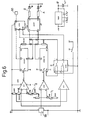
- FIG. 6 a circuit diagram for statistical evaluation of the encoder signals is presented in FIG. 6 as a possible example of the evaluation circuit.
- the designation of the blocks is shown in the drawing.
- signal processing by microprocessor is also possible.
- a second permanent magnet is attached to the rim 21-23 so that it is approximately at a distance from the center of the wheel which corresponds to that of the permanent magnet 40, which is moved in a pressure-dependent manner on the bellows 36, from the center of the wheel.
Landscapes
- Engineering & Computer Science (AREA)
- Mechanical Engineering (AREA)
- Measuring Fluid Pressure (AREA)
Priority Applications (1)
| Application Number | Priority Date | Filing Date | Title |
|---|---|---|---|
| AT87710016T ATE65967T1 (de) | 1986-10-08 | 1987-10-08 | Vorrichtung und verfahren zum ueberwachen des luftdruckes eines fahrzeugreifens. |
Applications Claiming Priority (4)
| Application Number | Priority Date | Filing Date | Title |
|---|---|---|---|
| DE8626700 | 1986-10-08 | ||
| DE8626700U | 1986-10-08 | ||
| DE8629898 | 1986-11-07 | ||
| DE8629898U | 1986-11-07 |
Publications (3)
| Publication Number | Publication Date |
|---|---|
| EP0263775A2 true EP0263775A2 (fr) | 1988-04-13 |
| EP0263775A3 EP0263775A3 (en) | 1988-09-07 |
| EP0263775B1 EP0263775B1 (fr) | 1991-08-07 |
Family
ID=25951133
Family Applications (1)
| Application Number | Title | Priority Date | Filing Date |
|---|---|---|---|
| EP87710016A Expired - Lifetime EP0263775B1 (fr) | 1986-10-08 | 1987-10-08 | Dispositif et méthode pour surveiller la pression d'un pneumatique d'automobile |
Country Status (4)
| Country | Link |
|---|---|
| EP (1) | EP0263775B1 (fr) |
| AT (1) | ATE65967T1 (fr) |
| DE (2) | DE3771992D1 (fr) |
| ES (1) | ES2023940B3 (fr) |
Cited By (6)
| Publication number | Priority date | Publication date | Assignee | Title |
|---|---|---|---|---|
| DE3909466A1 (de) * | 1989-03-22 | 1990-10-04 | Duerrwaechter E Dr Doduco | Verfahren und vorrichtung zur ueberwachung des reifendrucks |
| DE4108337C1 (fr) * | 1991-03-14 | 1992-07-30 | Doduco Gmbh + Co Dr. Eugen Duerrwaechter, 7530 Pforzheim, De | |
| WO1993007505A1 (fr) * | 1991-10-04 | 1993-04-15 | Doduco Gmbh + Co. Dr. Eugen Dürrwächter | Dispositif pour la determination de la force d'un champ magnetique |
| GB2267759A (en) * | 1992-06-06 | 1993-12-15 | Martin Merry | Monitoring pressure of rotating tyre |
| DE4408511A1 (de) * | 1994-03-14 | 1995-09-21 | Duerrwaechter E Dr Doduco | Verfahren zum Überwachen des Drucks in Luftreifen |
| CN1313293C (zh) * | 2003-10-14 | 2007-05-02 | 蔡青松 | 汽车轮胎的胎压监测装置 |
Families Citing this family (8)
| Publication number | Priority date | Publication date | Assignee | Title |
|---|---|---|---|---|
| DE3827354A1 (de) * | 1988-08-12 | 1990-05-23 | Alligator Ventilfab Gmbh | Vorrichtung zum ueberwachen des luftdruckes eines fahrzeugrades |
| DE3843814A1 (de) * | 1988-12-24 | 1990-07-05 | Alligator Ventilfab Gmbh | Vorrichtung mit einem um eine drehachse bewegten behaelter, insbesondere vorrichtung zum messen des reifendruckes in einem luftreifen |
| DE3843815A1 (de) * | 1988-12-24 | 1990-07-05 | Alligator Ventilfab Gmbh | Vorrichtung mit einem um eine drehachse bewegten behaelter, insbesondere vorrichtung zum messen des reifendruckes in einem luftreifen |
| DE3921383A1 (de) * | 1989-06-29 | 1991-01-10 | Alligator Ventilfab Gmbh | Vorrichtung mit einem um eine drehachse bewegten behaelter, insbesondere vorrichtung zum messen des reifendruckes in einem luftreifen |
| JP3412258B2 (ja) * | 1994-06-06 | 2003-06-03 | 株式会社デンソー | 増幅率可変装置及び移動体の内圧検出装置及び電磁誘導式変位検出装置及びタイヤ空気圧センサ |
| DE10047853B4 (de) * | 2000-08-11 | 2007-08-02 | Alligator Ventilfabrik Gmbh | Vorrichtung zum Messen des Reifendruckes in einem Luftreifen eines Fahrzeuges |
| ES2280456T3 (es) | 2001-07-19 | 2007-09-16 | Alligator Ventilfabrik Gmbh | Dispositivo para la medicion de la presion en un neumatico de un vehiculo. |
| DE102008013050A1 (de) | 2008-03-06 | 2009-09-10 | Beru Ag | Gehäusebefestigung an Snap-In-Ventil |
Family Cites Families (7)
| Publication number | Priority date | Publication date | Assignee | Title |
|---|---|---|---|---|
| CH240703A (de) * | 1943-11-30 | 1946-01-15 | Auderset Pierre | Vorrichtung zum Anzeigen von Druckverlusten in Luftreifen. |
| DE836602C (de) * | 1948-12-30 | 1952-04-15 | Ilse Grigull Geb Munsch | Vorrichtung zur UEberwachung des Luftdruckes von Fahrzeugreifen |
| US3654601A (en) * | 1970-03-10 | 1972-04-04 | Thayer Corp | Vehicle tire pressure warning system |
| US3978448A (en) * | 1975-06-09 | 1976-08-31 | Scovill Manufacturing Company | Vehicle-tire-air-pressure-sensing-and-indicating device |
| FR2471295A1 (fr) * | 1979-12-13 | 1981-06-19 | Schrader Sa | Dispositif comparateur de pression referencee pour pneu de vehicule avec affichage a distance |
| DE3037722A1 (de) * | 1980-10-06 | 1982-05-13 | Robert Bosch Gmbh, 7000 Stuttgart | Schaltungsanordnung zur ueberwachung des luftdrucks in fahrzeugreifen |
| DE3242291A1 (de) * | 1982-11-16 | 1984-05-17 | Moto Meter Ag, 7250 Leonberg | Vorrichtung zum messen des reifendrucks in luftreifen von fahrzeugen waehrend der fahrt |
-
1987
- 1987-10-08 DE DE8787710016T patent/DE3771992D1/de not_active Expired - Lifetime
- 1987-10-08 DE DE19873734053 patent/DE3734053A1/de not_active Withdrawn
- 1987-10-08 EP EP87710016A patent/EP0263775B1/fr not_active Expired - Lifetime
- 1987-10-08 AT AT87710016T patent/ATE65967T1/de not_active IP Right Cessation
- 1987-10-08 ES ES87710016T patent/ES2023940B3/es not_active Expired - Lifetime
Cited By (6)
| Publication number | Priority date | Publication date | Assignee | Title |
|---|---|---|---|---|
| DE3909466A1 (de) * | 1989-03-22 | 1990-10-04 | Duerrwaechter E Dr Doduco | Verfahren und vorrichtung zur ueberwachung des reifendrucks |
| DE4108337C1 (fr) * | 1991-03-14 | 1992-07-30 | Doduco Gmbh + Co Dr. Eugen Duerrwaechter, 7530 Pforzheim, De | |
| WO1993007505A1 (fr) * | 1991-10-04 | 1993-04-15 | Doduco Gmbh + Co. Dr. Eugen Dürrwächter | Dispositif pour la determination de la force d'un champ magnetique |
| GB2267759A (en) * | 1992-06-06 | 1993-12-15 | Martin Merry | Monitoring pressure of rotating tyre |
| DE4408511A1 (de) * | 1994-03-14 | 1995-09-21 | Duerrwaechter E Dr Doduco | Verfahren zum Überwachen des Drucks in Luftreifen |
| CN1313293C (zh) * | 2003-10-14 | 2007-05-02 | 蔡青松 | 汽车轮胎的胎压监测装置 |
Also Published As
| Publication number | Publication date |
|---|---|
| DE3771992D1 (de) | 1991-09-12 |
| EP0263775A3 (en) | 1988-09-07 |
| ES2023940B3 (es) | 1992-02-16 |
| ATE65967T1 (de) | 1991-08-15 |
| EP0263775B1 (fr) | 1991-08-07 |
| DE3734053A1 (de) | 1988-04-21 |
Similar Documents
| Publication | Publication Date | Title |
|---|---|---|
| EP0263775B1 (fr) | Dispositif et méthode pour surveiller la pression d'un pneumatique d'automobile | |
| EP1891343B1 (fr) | Joint a rotule dote d'un dispositif detecteur et procede de detection d'etancheite | |
| EP0371966B1 (fr) | Detecteur de pression de pneus pour vehicules a moteur | |
| EP3541642B1 (fr) | Suspension à ressort pour véhicule ferroviaire et système à ressort pour véhicule ferroviaire | |
| EP1503912A1 (fr) | Silentbloc a capteur de compression du ressort | |
| DE2257341A1 (de) | Vorrichtung zum automatischen erkennen unnormaler zustaende in fahrzeugreifen | |
| DE3150869A1 (de) | Reifendruckwarnvorrichtung | |
| EP0354238B1 (fr) | Dispositif de raccordement elastique, notamment a systeme integre de mesure d'efforts, et procede pour sa fabrication | |
| DE2618927A1 (de) | Vorrichtung zum fuehlen und anzeigen des luftdruckes in fahrzeugreifen | |
| DE19723037A1 (de) | Reifendruck-Überwachungssystem | |
| EP1789269A1 (fr) | Detection d'assiette de vehicule | |
| DE4000073A1 (de) | Ueberlastanzeige fuer fahrzeuge | |
| DE4108337C1 (fr) | ||
| EP3601948A1 (fr) | Détection de surcharge dans un composant de train de roulement | |
| EP0177788A2 (fr) | Dispositif pour mesurer la pression de gonflage pour la surveillance continue des pneumatiques de véhicules automobiles | |
| EP2818405A1 (fr) | Capteur | |
| EP0020809A1 (fr) | Commutateur sensible à la pression utilisable dans les indicateurs de pression de pneumatiques | |
| WO2020244825A1 (fr) | Appareil de mesure comprenant une bride, ainsi que bride et récipient | |
| DE3709587A1 (de) | Drucksensoranordnung fuer kraftfahrzeugreifen | |
| WO2019086191A1 (fr) | Capteur de champ magnétique et procédé de montage d'un aimant | |
| DE4124266A1 (de) | Vorrichtung zur erkennung des reifen-luftdruckes | |
| DE3209660A1 (de) | Luftdruck-anzeigevorrichtung fuer fahrzeugreifen | |
| DE102017213700A1 (de) | Abdichtungsanordnung | |
| EP4323727B1 (fr) | Système électromagnétique de mesure de course d'un piston, support d'aimant ainsi qu'utilisation d'un système électromagnétique de mesure de course d'un piston | |
| EP1375205A2 (fr) | Capteur pour la détection du mouvement relatif de deux pièces |
Legal Events
| Date | Code | Title | Description |
|---|---|---|---|
| PUAI | Public reference made under article 153(3) epc to a published international application that has entered the european phase |
Free format text: ORIGINAL CODE: 0009012 |
|
| AK | Designated contracting states |
Kind code of ref document: A2 Designated state(s): AT BE CH DE ES FR GB GR IT LI LU NL SE |
|
| PUAL | Search report despatched |
Free format text: ORIGINAL CODE: 0009013 |
|
| AK | Designated contracting states |
Kind code of ref document: A3 Designated state(s): AT BE CH DE ES FR GB GR IT LI LU NL SE |
|
| 17P | Request for examination filed |
Effective date: 19880923 |
|
| 17Q | First examination report despatched |
Effective date: 19900126 |
|
| GRAA | (expected) grant |
Free format text: ORIGINAL CODE: 0009210 |
|
| AK | Designated contracting states |
Kind code of ref document: B1 Designated state(s): AT BE CH DE ES FR GB GR IT LI LU NL SE |
|
| PG25 | Lapsed in a contracting state [announced via postgrant information from national office to epo] |
Ref country code: SE Effective date: 19910807 Ref country code: NL Effective date: 19910807 Ref country code: GR Free format text: LAPSE BECAUSE OF FAILURE TO SUBMIT A TRANSLATION OF THE DESCRIPTION OR TO PAY THE FEE WITHIN THE PRESCRIBED TIME-LIMIT Effective date: 19910807 Ref country code: BE Effective date: 19910807 |
|
| REF | Corresponds to: |
Ref document number: 65967 Country of ref document: AT Date of ref document: 19910815 Kind code of ref document: T |
|
| REF | Corresponds to: |
Ref document number: 3771992 Country of ref document: DE Date of ref document: 19910912 |
|
| ITF | It: translation for a ep patent filed | ||
| PG25 | Lapsed in a contracting state [announced via postgrant information from national office to epo] |
Ref country code: AT Effective date: 19911008 |
|
| PG25 | Lapsed in a contracting state [announced via postgrant information from national office to epo] |
Ref country code: LU Free format text: LAPSE BECAUSE OF NON-PAYMENT OF DUE FEES Effective date: 19911031 |
|
| GBT | Gb: translation of ep patent filed (gb section 77(6)(a)/1977) | ||
| ET | Fr: translation filed | ||
| NLV1 | Nl: lapsed or annulled due to failure to fulfill the requirements of art. 29p and 29m of the patents act | ||
| REG | Reference to a national code |
Ref country code: ES Ref legal event code: FG2A Ref document number: 2023940 Country of ref document: ES Kind code of ref document: B3 |
|
| PLBE | No opposition filed within time limit |
Free format text: ORIGINAL CODE: 0009261 |
|
| STAA | Information on the status of an ep patent application or granted ep patent |
Free format text: STATUS: NO OPPOSITION FILED WITHIN TIME LIMIT |
|
| 26N | No opposition filed | ||
| PGFP | Annual fee paid to national office [announced via postgrant information from national office to epo] |
Ref country code: DE Payment date: 19921124 Year of fee payment: 6 |
|
| PG25 | Lapsed in a contracting state [announced via postgrant information from national office to epo] |
Ref country code: DE Effective date: 19940701 |
|
| PGFP | Annual fee paid to national office [announced via postgrant information from national office to epo] |
Ref country code: CH Payment date: 19960111 Year of fee payment: 9 |
|
| PG25 | Lapsed in a contracting state [announced via postgrant information from national office to epo] |
Ref country code: LI Effective date: 19961031 Ref country code: CH Effective date: 19961031 |
|
| REG | Reference to a national code |
Ref country code: CH Ref legal event code: PL |
|
| PGFP | Annual fee paid to national office [announced via postgrant information from national office to epo] |
Ref country code: GB Payment date: 20000929 Year of fee payment: 14 |
|
| PGFP | Annual fee paid to national office [announced via postgrant information from national office to epo] |
Ref country code: ES Payment date: 20001016 Year of fee payment: 14 |
|
| PGFP | Annual fee paid to national office [announced via postgrant information from national office to epo] |
Ref country code: FR Payment date: 20001019 Year of fee payment: 14 |
|
| PG25 | Lapsed in a contracting state [announced via postgrant information from national office to epo] |
Ref country code: GB Free format text: LAPSE BECAUSE OF NON-PAYMENT OF DUE FEES Effective date: 20011008 |
|
| PG25 | Lapsed in a contracting state [announced via postgrant information from national office to epo] |
Ref country code: ES Free format text: LAPSE BECAUSE OF NON-PAYMENT OF DUE FEES Effective date: 20011009 |
|
| REG | Reference to a national code |
Ref country code: GB Ref legal event code: IF02 |
|
| GBPC | Gb: european patent ceased through non-payment of renewal fee |
Effective date: 20011008 |
|
| PG25 | Lapsed in a contracting state [announced via postgrant information from national office to epo] |
Ref country code: FR Free format text: LAPSE BECAUSE OF NON-PAYMENT OF DUE FEES Effective date: 20020628 |
|
| REG | Reference to a national code |
Ref country code: FR Ref legal event code: ST |
|
| REG | Reference to a national code |
Ref country code: ES Ref legal event code: FD2A Effective date: 20021113 |
|
| PG25 | Lapsed in a contracting state [announced via postgrant information from national office to epo] |
Ref country code: IT Free format text: LAPSE BECAUSE OF NON-PAYMENT OF DUE FEES Effective date: 20051008 |