EP0177800A2 - Multiplexeur/démultiplexeur de longueurs d'onde optique biréfringent - Google Patents
Multiplexeur/démultiplexeur de longueurs d'onde optique biréfringent Download PDFInfo
- Publication number
- EP0177800A2 EP0177800A2 EP85111612A EP85111612A EP0177800A2 EP 0177800 A2 EP0177800 A2 EP 0177800A2 EP 85111612 A EP85111612 A EP 85111612A EP 85111612 A EP85111612 A EP 85111612A EP 0177800 A2 EP0177800 A2 EP 0177800A2
- Authority
- EP
- European Patent Office
- Prior art keywords
- reflected
- polarization
- parallel
- polarized beams
- propagated
- Prior art date
- Legal status (The legal status is an assumption and is not a legal conclusion. Google has not performed a legal analysis and makes no representation as to the accuracy of the status listed.)
- Withdrawn
Links
Images


Classifications
-
- G—PHYSICS
- G02—OPTICS
- G02B—OPTICAL ELEMENTS, SYSTEMS OR APPARATUS
- G02B6/00—Light guides; Structural details of arrangements comprising light guides and other optical elements, e.g. couplings
- G02B6/24—Coupling light guides
- G02B6/26—Optical coupling means
- G02B6/28—Optical coupling means having data bus means, i.e. plural waveguides interconnected and providing an inherently bidirectional system by mixing and splitting signals
- G02B6/293—Optical coupling means having data bus means, i.e. plural waveguides interconnected and providing an inherently bidirectional system by mixing and splitting signals with wavelength selective means
- G02B6/29302—Optical coupling means having data bus means, i.e. plural waveguides interconnected and providing an inherently bidirectional system by mixing and splitting signals with wavelength selective means based on birefringence or polarisation, e.g. wavelength dependent birefringence, polarisation interferometers
-
- G—PHYSICS
- G02—OPTICS
- G02B—OPTICAL ELEMENTS, SYSTEMS OR APPARATUS
- G02B27/00—Optical systems or apparatus not provided for by any of the groups G02B1/00 - G02B26/00, G02B30/00
- G02B27/28—Optical systems or apparatus not provided for by any of the groups G02B1/00 - G02B26/00, G02B30/00 for polarising
- G02B27/283—Optical systems or apparatus not provided for by any of the groups G02B1/00 - G02B26/00, G02B30/00 for polarising used for beam splitting or combining
-
- G—PHYSICS
- G02—OPTICS
- G02B—OPTICAL ELEMENTS, SYSTEMS OR APPARATUS
- G02B27/00—Optical systems or apparatus not provided for by any of the groups G02B1/00 - G02B26/00, G02B30/00
- G02B27/28—Optical systems or apparatus not provided for by any of the groups G02B1/00 - G02B26/00, G02B30/00 for polarising
- G02B27/288—Filters employing polarising elements, e.g. Lyot or Solc filters
-
- G—PHYSICS
- G02—OPTICS
- G02B—OPTICAL ELEMENTS, SYSTEMS OR APPARATUS
- G02B6/00—Light guides; Structural details of arrangements comprising light guides and other optical elements, e.g. couplings
- G02B6/10—Light guides; Structural details of arrangements comprising light guides and other optical elements, e.g. couplings of the optical waveguide type
- G02B6/105—Light guides; Structural details of arrangements comprising light guides and other optical elements, e.g. couplings of the optical waveguide type having optical polarisation effects
-
- G—PHYSICS
- G02—OPTICS
- G02B—OPTICAL ELEMENTS, SYSTEMS OR APPARATUS
- G02B6/00—Light guides; Structural details of arrangements comprising light guides and other optical elements, e.g. couplings
- G02B6/24—Coupling light guides
- G02B6/26—Optical coupling means
- G02B6/28—Optical coupling means having data bus means, i.e. plural waveguides interconnected and providing an inherently bidirectional system by mixing and splitting signals
- G02B6/2804—Optical coupling means having data bus means, i.e. plural waveguides interconnected and providing an inherently bidirectional system by mixing and splitting signals forming multipart couplers without wavelength selective elements, e.g. "T" couplers, star couplers
- G02B6/2817—Optical coupling means having data bus means, i.e. plural waveguides interconnected and providing an inherently bidirectional system by mixing and splitting signals forming multipart couplers without wavelength selective elements, e.g. "T" couplers, star couplers using reflective elements to split or combine optical signals
-
- G—PHYSICS
- G02—OPTICS
- G02B—OPTICAL ELEMENTS, SYSTEMS OR APPARATUS
- G02B6/00—Light guides; Structural details of arrangements comprising light guides and other optical elements, e.g. couplings
- G02B6/24—Coupling light guides
- G02B6/26—Optical coupling means
- G02B6/27—Optical coupling means with polarisation selective and adjusting means
- G02B6/2706—Optical coupling means with polarisation selective and adjusting means as bulk elements, i.e. free space arrangements external to a light guide, e.g. polarising beam splitters
- G02B6/2713—Optical coupling means with polarisation selective and adjusting means as bulk elements, i.e. free space arrangements external to a light guide, e.g. polarising beam splitters cascade of polarisation selective or adjusting operations
- G02B6/272—Optical coupling means with polarisation selective and adjusting means as bulk elements, i.e. free space arrangements external to a light guide, e.g. polarising beam splitters cascade of polarisation selective or adjusting operations comprising polarisation means for beam splitting and combining
-
- G—PHYSICS
- G02—OPTICS
- G02B—OPTICAL ELEMENTS, SYSTEMS OR APPARATUS
- G02B6/00—Light guides; Structural details of arrangements comprising light guides and other optical elements, e.g. couplings
- G02B6/24—Coupling light guides
- G02B6/26—Optical coupling means
- G02B6/27—Optical coupling means with polarisation selective and adjusting means
- G02B6/2753—Optical coupling means with polarisation selective and adjusting means characterised by their function or use, i.e. of the complete device
- G02B6/2766—Manipulating the plane of polarisation from one input polarisation to another output polarisation, e.g. polarisation rotators, linear to circular polarisation converters
-
- G—PHYSICS
- G02—OPTICS
- G02B—OPTICAL ELEMENTS, SYSTEMS OR APPARATUS
- G02B6/00—Light guides; Structural details of arrangements comprising light guides and other optical elements, e.g. couplings
- G02B6/24—Coupling light guides
- G02B6/26—Optical coupling means
- G02B6/27—Optical coupling means with polarisation selective and adjusting means
- G02B6/2753—Optical coupling means with polarisation selective and adjusting means characterised by their function or use, i.e. of the complete device
- G02B6/2773—Polarisation splitting or combining
Definitions
- This invention relates to new and improved birefringent optical wavelength multiplexers/ demultiplexers. Accordingly, it is a general object of this invention to provide new and improved devices of such character.
- Optical wavelength division multiplexing is a technique for combining two or more light beams with different wavelengths along a single optical path.
- Optical wavelength division demultiplexing involves the separation of these signals from one another at the other end of that path.
- Optical multiplexers and demultiplexers are often interchangeable with each other.
- Optical wavelength division multiplexing and demultiplexing can be used in optical communications systems to multiply the effective information capacity (or signal bandwidth) of a single optical communication pathway.
- the medium may be optical fiber, free space (or air), water, etc. Individual channels can be transmitted along the path on different optical wavelength carriers, each of which propagates independently of the others.
- multiplexers and demultiplexers described herein provide for an arbitrarily small separation between channel wavelengths so that a required number of channels can be located within an acceptable wavelength range therefor.
- This feature is especially desirable in dense media, such as glass fibers or water, since such media generally have a very limited wavelength range over which the chromatic optical dispersion is near zero and the total losses are small.
- dense media such as glass fibers or water
- the wavelength range might be approximately 60 nanometers, depending upon the glass. (Contemporary single-mode fibers used at about 1.3pm have a wavelength range thereabout.) Outside of this narrow range, additional channels are of little value.
- the channel spacing of the multiplexed signals can be as small as desired, as will be made more apparent hereinafter.
- the size of the spacing is limited primarily by the stability and spectral width of the optical sources that are utilized, such as lasers.
- the locations of and spacings between the channel wavelengths can be determined by the thicknesses of prisms in the multiplexers, and these are the only fabrication parameters which generally need be changed to customize the units for a specific application.
- the devices can be continually tuned by varying the effective thicknesses of the prisms.
- a multiplexer and a demultiplexer can be independently tuned to exactly match the wavelengths of two lasers in the system, so that the laser wavelengths do not have to be precisely specified.
- the invention is primarily applicable to a fiber optical system, it is to be understood that its precepts can be applied to free-space and other optical communications applications, as would be apparent to those skilled in the art.
- Dichroic beamsplitter method In the dichroic beamsplitter method, two light signals impinge upon a beam-splitter that is designed to transmit one wavelength and to reflect the other. At the multiplexer end, one wavelength passes through the beamsplitter, and the other wavelength is incident at such an angle that it is reflected by the beamsplitter along the same optical path as the first. Both beams are then coupled by the same optics into a system fiber.
- one wavelength passes through a beamsplitter, while the other wavelength is reflected from the beamsplitter.
- the individual beams thus separated can then be individually processed.
- more than one device can, in principle, be used in a tree or series configuration.
- Diffraction grating method A grating is utilized to diffract different wavelengths of light at different angles such that multiple wavelengths are separated from one another in different directions of propagation or combined to form a single beam when incident from multiple angles. Diffraction gratings have the potential advantage that a single device is able to handle more than two wavelengths, while all other previously known types can only handle two sets of wavelengths per stage.
- diffraction gratings are inherently polarization sensitive.
- the continual polarization variations in the fiber result in significant fading problems in the receiver.
- any change of laser wavelength causes the focused spot of light to wander from the optimal position at the end of the fiber.
- this can be somewhat accommodated by utilizing output fibers with much larger diameters than that of the system fiber, or by using detector cells themselves to collect the light.
- the fabrication of such a device is extremely difficult.
- the fibers must be bunched very closely together, at specific directions with respect to one another. This usually requires individual adjustments with micromanipulators, or precision fiber-aligning grooves which cannot be adjusted.
- Holographic devices are essentially diffraction gratings that are made by the optical technique of holography. Often, the hologram is designed to perform lens type operations as well as diffraction, so some external optics can be eliminated.
- holographic gratings usually have higher throughput losses, especially when combined with focusing functions.
- Another object of this invention is to provide for a new and improved optical multiplexer and demultiplexer, utilizing neither dichroic filters nor diffraction to achieve wavelength selectivity.
- Still another object of this invention is to provide for a new and improved optical multiplexer and demultiplexer utilizing the optical technique of birefringent interferometry.
- Yet another object of this invention is to provide for a new and improved optical multiplexer and demultiplexer utilizing no highly wavelength sensitive optical coatings, and in which wide bandwidth antireflection coatings and polarization beamsplitter coatings can be used that do not need to be respecified for each system application.
- Still yet another object of this invention is to provide for a new and improved optical multiplexer and demultiplexer in which the channel wavelengths and spacings are determined by the thickness of a single crystal in each unit and in which, otherwise, all units can be identical.
- Yet still another object of this invention is to provide for a new and improved birefringent optical wavelength multiplexer/demultiplexer in which, unlike any other previous known multiplexing technique, an individual unit can be independently tuned so that the spacing and location of its wavelength passband can be selected and, in the case of two channels, any two lasers can be selected and the multiplexer/demultiplexer later can be precisely tuned to those wavelengths.
- Still yet another object of this invention is to provide for a new and improved optical wavelength multiplexer/demultiplexer in which a standard configuration thereof is insensitive to polarization changes.
- Yet still another object of this invention is to provide for a new and improved optical wavelength multiplexer/demultiplexer, which, when multiple units are utilized to multiplex (or demultiplex) more than two channels, only one unit, the one closest to the system link, processes channels which are closest together.
- a birefringent optical wavelength multiplexer/demultiplexer includes beamsplitting means, reflecting means, and a birefringent element.
- a first polarization beamsplitting means splits an applied collimated beam of light into two linearly polarized beams whose directions of propagation are perpendicular to each other.
- a first reflecting means reflects one of the linearly polarized beams parallel to the other polarized beam.
- a birefringent element having a pair of opposed parallel surfaces, with an optical axis oriented nominally parallel to the surfaces, is oriented with its parallel surfaces perpendicular to the direction of propagation of the linearly polarized beams.
- the optical axis is oriented half way between the two polarized beams incident upon the element, 45° from the polarization axis of each beam.
- a second reflecting means reflects the other polarized beam, following propagation of the other beam through the element, in a direction perpendicular to that of the one polarized beam following propagation of the one polarized beam through the element.
- a second polarized beam splitting means is oriented to receive both the reflected other beam and the propagated one beam.
- the reflected other beam is transmitted by the second polarization beam splitting means.
- the propagated one beam is reflected by the second polarization beam splitting means, whereby the reflected other beam and the propagated one beam are combined and transmitted outwardly from a first port, and
- the propagated other beam and the propagated one beam have polarization states which are linearly polarized perpendicular to the respective applied polarized beams, the reflected other beam is reflected by the second polarization beam splitting means.
- the propagated one beam is transmitted by the second polarization beam splitting means, whereby the reflected other beam and the propagated one beam are combined and transmitted outwardly from the second port.
- a birefringent optical wavelength multiplexer/demultiplexer includes a first polarization beam splitting means for splitting an applied collimated beam of light into two linearly polarized beams whose directions of propagation are at an angle with one another.
- a first reflecting means reflects one of the linearly polarized beams parallel to the other.
- a birefringent element has a pair of opposed parallel surfaces. An optical axis is oriented nominally parallel to the surfaces. The element is oriented with the parallel surfaces perpendicular to the direction of propagation of the linearly polarized beams. The optical axis is oriented half way between the two polarized beams incident upon the element, equiangular from the polarization axis of each beam.
- a second reflecting means reflects the other of the linearly polarized beams following propagation of the other beam through the element, in the direction perpendicular to that of the one of the polarized beams following propagation of the one polarized beam through the element.
- a second polarized beam splitting means is oriented to receive both the reflected other beam and the propagated one beam.
- the reflected other beam is transmitted by the second polarization beam splitting means, and the propagated one beam is reflected by the second polarization beam splitting means, whereby the reflected other beam and the propagated one beam are combined and transmitted outwardly from a first port
- the propagated other beam and the propagated one beam have polarization states which are linearly polarized perpendicular to the respective applied polarized beams
- the reflected other beam is reflected by the second polarization beam splitting means, and the propagated one beam is transmitted by the second polarization beam splitting means, whereby the reflected other beam and the reflected one beam are combined and transmitted outwardly from the second port.
- a birefringent multiplexer/demultiplexer includes a tree structure of three comb filter units, A, B and C. Two of the comb filters A and B have a basic channel spacing of 2 ⁇ .
- the comb filter A receives signals at wavelengths X 1 and ⁇ 3 along separate channels thereof and combines them onto a first output path.
- the comb filter B receives signals at wavelengths ⁇ 2 and ⁇ 4 along separate channels of the filter B, having the same channel spacing as the comb filter A but tuned a distance 4X away therefrom, and combines the signals ⁇ 2 and ⁇ 4 onto a second output path.
- the first and the second output paths are coupled to two separate ports of the third comb filter unit C which has a channel spacing equal to ⁇ , whereby signals at ⁇ 1 and ⁇ 3 travel along the first path and signals at ⁇ 2 and ⁇ 4 travel along the second path, and all four signals ⁇ 1' ⁇ 2' ⁇ 3 and ⁇ 4 are combined onto a third output path.
- This invention is directed to apparatus which multiplexes or demultiplexes any number, n, of wavelength- separated channels, using a tree configuration of n-1 birefringent interferometer units. All units in the tree configuration can be identically constructed, although some units may have different lengths of birefringent crystal elements than others.
- a birefringent interferometer unit acts as a bidirectional optical comb filter, which transmits alternate wavelength channels along different paths, that is, each of the two transmission paths of the comb filter has a periodic power-vs-wavelength transfer characteristic, each essentially one-half of a period out of phase with the other.
- FIG. 1 there is shown a block diagram of a typical birefringent multiplexer/demultiplexer 11 in accordance with this invention.
- the birefringent multiplexer/demultiplexer 11 uses a tree structure of comb filter units 12, 13, 14.
- Each comb filter unit 12, 13, 14, as shown in Fig. 1 contains a graph of the transfer functions for the two transmission paths through it.
- a four-channel device, as depicted in Fig. 1, is shown for simplicity.
- the lines 16, 17 between the units represent interconnecting fibers or, alternatively, can represent freely propagating collimated light beams.
- Each of the two comb filters 12, 13 has a basic channel spacing of 2 ⁇ .
- the channels have this wavelength separation and travel separately along two transmission paths of the comb filter unit.
- Each unit 12, 13 has the same channel spacing, but tuned ⁇ away from each other.
- the two comb filters 12, 13 guide the channels along different paths, separated on the left and combined on the right.
- the entire configuration is bidirectional for each wavelength path.
- the overall system heretofore described can be used to multiplex four channels onto a single fiber, for example.
- a similar unit can be used at the receiving end of the system, in reverse manner, to demultiplex the four channels from one another.
- both ends of the system include both transmitters and receivers, so that the devices at either end can act as multiple wavelength duplexers.
- any one or more wavelength channels can propagate from left to right, while others propagate from right to left.
- the comb filter unit 20 includes two polarization beam splitters 21, 22, two reflecting surfaces 23, 24, and a birefringent element 26 having parallel opposite sides 27, 28.
- the birefringent element 26 can be crystalline, such as quartz or calcite, but can be, alternatively, any other birefringent material such as stressed plastic, electro-optical material, etc.
- the optical axis of the birefringent element 26 is nominally parallel to its two parallel surfaces 27, 28.
- the optical axis is oriented half way between the axes of polarization of the two beams incident upon it (i.e., 45° from each other).
- the parallel surfaces 27, 28 are oriented perpendicular to the common direction of propagation of the two beams.
- a light beam is provided at the input port 25, at the left of Fig. 2.
- Output ports 1, 2 are provided at the right, and top right, of the figure, as shown.
- a pair of light beams can be provided at the right, and top right, for combined output at the left port 25.
- a collimated beam of light (whose polarization state is immaterial) enters the input port 25 and is directed onto the first polarization beam splitter 21.
- the beam splitter 21 splits the beam into two linearly polarized beams 29A, 29B whose directions of propagation can be perpendicular to one another as shown, or at any other angle.
- the reflecting surface 23 reflects beam 29A parallel to the other 29B, and both beams 29A, 29B enter the birefringent element 26.
- both beams 29A, 29B undergo essentially the same transformation.
- the component of the optical electric field vector which is parallel to the extraordinary axis of the material propagates faster or slower, depending upon the material, than the component parallel to the ordinary axis.
- these two components are out of phase by an amount proportional to the thickness of the birefringent material, and inversely proportional to the optical wavelength.
- polarization state which, depending on the phase, is one of the following: (1) linearly polarized parallel to the input beam polarization, (2) linearly polarized perpendicular to the input beam polarization, or (3) elliptically or circularly polarized.
- the beam component 29B that entered the input port 25 and was not reflected by the polarization splitter 21 is reflected by the second reflecting surface 24 towards the second polarization beam splitter 22.
- the other beam 29A that was reflected by the first polarization beam splitter 21 and the first reflecting surface 23 is also directed to the second polarization beam splitter 22.
- the light beam When elliptical or circularly polarized light occurs, the light beam has both 0° and 90° components in both beams 29A, 29B, and thus, components of each are transmitted through the two ports 1, 2.
- the first transformation i.e., linearly polarized parallel to the input beam polarization occurs for wavelengths a for which where and p is equal to the number of half-wavelengths of retardation that light of wavelength a experiences while traversing the thickness t.
- the second transformation wherein the vector components are linearly polarized perpendicular to the input beam polarization, occurs for those wavelengths ⁇ where
- a comb filter 20 To tune a comb filter 20 to a desired wavelength, it is only necessary to replace the birefringent prism 26 with one having a different thickness. Alternatively, or supplementary, a material can be used with a different ⁇ n. Further, any technique which changes the overall retardation through the crystal path can be used to tune the wavelength passband.
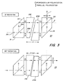
- Fig. 3 depicts a mechanically tunable multiplexer 30.
- the multiplexer 30 utilizes a pair of wedges 136, 236 of birefringent material arranged such that moving one 136 relative to the other 236 changes the effective thickness of the material through which the light propagates, and thus varies the overall retardation.
- This multiplexer 30 provides for a continuous change in both ⁇ p and ⁇ , so that in a two-channel system, the multiplexer 30 can be tuned precisely to the wavelengths of the two lasers to be used in a system, instead of having to precisely specify the wavelengths of the lasers to suit the multiplexer 30.
- FIG. 4 Another type of mechanically tunable multiplexer 40 is depicted in Fig. 4, which shows two birefringent compensator plates 41, 42 following the main birefringent prism 43.
- the apparatus in Fig. 4 utilizes a quarter-wave plate 41 oriented at 45° following the main prism 43.
- the quarter wave plate 41 assures that any light exiting the plate 41 is linearly polarized at some wavelength- dependent angle.
- the subsequent half-plate 42 acts a polarization rotator. Rotation of the half-wave plate 42 continuously changes the wavelengths of light which end at the proper polarization states to exit solely at one exit port 1 or the other 2. Hence, rotating the half-wave plate 42 tunes the entire wavelength passband over a range of approximately one full period.
- the configurations described hereinabove generally assume that light enters the multiplexer from a separate signal source, or enters the demultiplexer from a system fiber, having no known polarization state.
- Such configurations set forth hereinabove are designed to be polarization-insensitive, so that they can perform optimally independent of whether the polarization of each light signal was random, linear, continually changing over time, etc.
- FIG. 5 there is shown a block diagram of a four-channel multiplexer 50 that can be constructed with a single birefringent stage 51, in lieu of three as described hereinabove.
- using polarized signals reduces the number of birefringent comb filters units 50 from n-1 to (n/2)-1, where n is a power of 2.
Landscapes
- Physics & Mathematics (AREA)
- General Physics & Mathematics (AREA)
- Optics & Photonics (AREA)
- Semiconductor Lasers (AREA)
- Optical Integrated Circuits (AREA)
Applications Claiming Priority (2)
| Application Number | Priority Date | Filing Date | Title |
|---|---|---|---|
| US06/650,012 US4566761A (en) | 1984-09-13 | 1984-09-13 | Birefringent optical wavelength multiplexer/demultiplexer |
| US650012 | 1984-09-13 |
Related Child Applications (2)
| Application Number | Title | Priority Date | Filing Date |
|---|---|---|---|
| EP19890120129 Division EP0362900A2 (fr) | 1984-09-13 | 1985-09-13 | Multiplexeur de longueurs d'ondes optiques à quatre canaux |
| EP89120129.5 Division-Into | 1985-09-13 |
Publications (2)
| Publication Number | Publication Date |
|---|---|
| EP0177800A2 true EP0177800A2 (fr) | 1986-04-16 |
| EP0177800A3 EP0177800A3 (fr) | 1988-10-05 |
Family
ID=24607120
Family Applications (1)
| Application Number | Title | Priority Date | Filing Date |
|---|---|---|---|
| EP85111612A Withdrawn EP0177800A3 (fr) | 1984-09-13 | 1985-09-13 | Multiplexeur/démultiplexeur de longueurs d'onde optique biréfringent |
Country Status (4)
| Country | Link |
|---|---|
| US (1) | US4566761A (fr) |
| EP (1) | EP0177800A3 (fr) |
| JP (1) | JPS6173919A (fr) |
| CA (1) | CA1255135A (fr) |
Cited By (5)
| Publication number | Priority date | Publication date | Assignee | Title |
|---|---|---|---|---|
| EP0245165A1 (fr) * | 1986-05-06 | 1987-11-11 | Matra | Dispositif optiques de transmission de données à multiplexage de fréquence |
| EP0288769A1 (fr) * | 1987-04-02 | 1988-11-02 | Gte Laboratories Incorporated | Multiplexeur/démultiplexeur de longueur d'onde multivoie |
| AU602079B2 (en) * | 1987-05-15 | 1990-09-27 | Alcatel N.V. | Optical communication system |
| EP0268523B1 (fr) * | 1986-11-04 | 1993-02-17 | Oki Electric Industry Company, Limited | Coupleur optique pour amplificateur direct optique |
| US7257287B2 (en) | 1998-08-21 | 2007-08-14 | Avanex Corporation | Optical interleaver |
Families Citing this family (66)
| Publication number | Priority date | Publication date | Assignee | Title |
|---|---|---|---|---|
| NL8104123A (nl) * | 1981-09-07 | 1983-04-05 | Philips Nv | Optische multiplex- en demultiplexinrichting. |
| US4677398A (en) * | 1985-07-25 | 1987-06-30 | The United States Of America As Represented By The Secretary Of The Army | Pulsed digital multiplex laser generator |
| US4671613A (en) * | 1985-11-12 | 1987-06-09 | Gte Laboratories Inc. | Optical beam splitter prism |
| US4802765A (en) * | 1986-06-12 | 1989-02-07 | Zygo Corporation | Differential plane mirror having beamsplitter/beam folder assembly |
| JPH0738049B2 (ja) * | 1986-08-09 | 1995-04-26 | 富士通株式会社 | 光デバイス |
| DE3802538A1 (de) * | 1987-01-28 | 1988-08-11 | Olympus Optical Co | Vorrichtung zum erfassen von fotomagnetischen signalen |
| US4745591A (en) * | 1987-02-24 | 1988-05-17 | Gte Laboratories Incorporated | Multiple channel wavelength division multiplexer/demultiplexer |
| US4795246A (en) * | 1987-07-30 | 1989-01-03 | Loro Albert | Differential interference contrast microscope using non-uniformly deformed plastic birefringent components |
| US4904043A (en) * | 1988-06-15 | 1990-02-27 | American Telephone And Telegraph Company, At&T Bell Laboratories | Optical data link dual wavelength coupler |
| JPH0816739B2 (ja) * | 1988-12-22 | 1996-02-21 | 日本電気株式会社 | 波長分岐挿入素子 |
| US5194980A (en) * | 1992-05-29 | 1993-03-16 | Eastman Kodak Company | Thresholded, high power laser beam scanning system |
| US5296958A (en) * | 1992-05-29 | 1994-03-22 | Eastman Kodak Company | Multiple wavelength laser beam scanning system |
| EP0593205A1 (fr) * | 1992-10-16 | 1994-04-20 | AT&T Corp. | Coupleur optique |
| US5751384A (en) | 1995-05-23 | 1998-05-12 | The Board Of Regents Of The University Of Colorado | Color polarizers for polarizing an additive color spectrum along a first axis and it's compliment along a second axis |
| US6183091B1 (en) * | 1995-04-07 | 2001-02-06 | Colorlink, Inc. | Color imaging systems and methods |
| US5999240A (en) | 1995-05-23 | 1999-12-07 | Colorlink, Inc. | Optical retarder stack pair for transforming input light into polarization states having saturated color spectra |
| US6707516B1 (en) | 1995-05-23 | 2004-03-16 | Colorlink, Inc. | Single-panel field-sequential color display systems |
| US6882384B1 (en) * | 1995-05-23 | 2005-04-19 | Colorlink, Inc. | Color filters and sequencers using color selective light modulators |
| US6417892B1 (en) | 1995-05-23 | 2002-07-09 | Colorlink, Inc. | Color filters, sequencers and displays using color selective light modulators |
| US5867291A (en) | 1996-10-29 | 1999-02-02 | Chorum Technologies Inc. | Programmable wavelength router |
| US6285478B1 (en) | 1998-03-26 | 2001-09-04 | Chorum Technologies Lp | Programmable optical add/drop device |
| US6166838A (en) | 1997-03-24 | 2000-12-26 | Chorum Technologies, Inc. | Optical add/drop wavelength switch |
| US6115155A (en) | 1996-10-29 | 2000-09-05 | Chorum Technologies Inc. | System for dealing with faults in an optical link |
| US6847786B2 (en) | 1996-10-29 | 2005-01-25 | Ec-Optics Technology, Inc. | Compact wavelength filter using optical birefringence and reflective elements |
| US6243200B1 (en) | 2000-03-02 | 2001-06-05 | Chorum Technologies, Inc. | Optical wavelength router based on polarization interferometer |
| US6545783B1 (en) | 1996-10-29 | 2003-04-08 | Chorum Technologies Lp | Optical wavelength add/drop multiplexer |
| US6163393A (en) | 1996-10-29 | 2000-12-19 | Chorum Technologies Inc. | Method and apparatus for wavelength multipexing/demultiplexing |
| US6049404A (en) | 1997-04-02 | 2000-04-11 | Macro-Vision Communications Inc. | N+M digitally programmable optical routing switch |
| US6094246A (en) | 1998-01-06 | 2000-07-25 | Chorum Technologies | Acute twist nematic liquid crystal electro-optic modulator for use in an infrared optical communication system having extinction ratio of -25db |
| US6441934B1 (en) * | 1998-02-13 | 2002-08-27 | Apa Optics, Inc. | Multiplexer and demultiplexer for single mode optical fiber communication links |
| US6647209B1 (en) | 1998-02-13 | 2003-11-11 | Apa Optics, Inc. | Multiplexer and demultiplexer for single mode optical fiber communication links |
| WO2000011510A1 (fr) * | 1998-08-21 | 2000-03-02 | Corning Incorporated | Filtre periodique accordable |
| US6134358A (en) | 1998-08-27 | 2000-10-17 | Chorum Technologies Inc. | N x N switch array with reduced components |
| US6259560B1 (en) | 1999-04-16 | 2001-07-10 | The United States Of America As Represented By The Secretary Of The Navy | Continuously variable beam combiner |
| US6519060B1 (en) | 1999-06-04 | 2003-02-11 | Chorum Technologies Lp | Synchronous optical network in frequency domain |
| US6169626B1 (en) | 1999-06-29 | 2001-01-02 | E-Tek Dynamics | Optical signal interleaver |
| US6275322B1 (en) | 1999-06-08 | 2001-08-14 | Jds Uniphase Corporation | Michelson phase shifter interleaver/deinterleavers |
| US6594054B1 (en) | 1999-09-15 | 2003-07-15 | Lucent Technologies Inc. | Filtering system for eliminating dispersion and method for doing same |
| US6396609B1 (en) | 1999-12-20 | 2002-05-28 | Chorum Technologies, Lp | Dispersion compensation for optical systems |
| US6335830B1 (en) | 1999-12-31 | 2002-01-01 | Jds Uniphase Corporation | Double-pass folded interleaver/deinterleavers |
| US6301046B1 (en) | 1999-12-31 | 2001-10-09 | Jds Uniphase Corporation | Interleaver/deinterleavers causing little or no dispersion of optical signals |
| US6337770B1 (en) | 1999-12-31 | 2002-01-08 | Jds Uniphase Corporation | Single-pass folded interleaver/deinterleavers |
| US6532321B1 (en) * | 2000-02-16 | 2003-03-11 | Adc Telecommunications, Inc. | Fiber optic isolator for use with multiple-wavelength optical signals |
| US6333816B1 (en) | 2000-03-03 | 2001-12-25 | Jds Uniphase Corporation | Apparatus capable of operating as interleaver/deinterleavers or filters |
| US6421177B1 (en) | 2000-03-03 | 2002-07-16 | Arroyo Optics, Inc. | Interleaving optical filter |
| US6400860B1 (en) * | 2000-03-21 | 2002-06-04 | Lucent Technologies Inc. | Wavelength selective polarization beam splitter/combiner |
| US6559992B2 (en) | 2000-03-27 | 2003-05-06 | Chorum Technologies Lp | Adjustable chromatic dispersion compensation |
| US6426816B1 (en) | 2000-05-01 | 2002-07-30 | Chorum Technologies, Lp | Wide transmission optical comb filter with wide pass band and wide stop band |
| US6553156B1 (en) * | 2000-06-30 | 2003-04-22 | Oplink Communications, Inc. | Optical isolators with ultra-low polarization mode dispersion |
| WO2002021170A1 (fr) | 2000-09-05 | 2002-03-14 | Arroyo Optics, Inc. | Systeme et procede pour la fabrication de composants ayant une longueur de trajet optique precise |
| US6704143B1 (en) * | 2000-10-23 | 2004-03-09 | Adc Telecommunications, Inc. | Method and apparatus for adjusting an optical element to achieve a precise length |
| WO2002043296A2 (fr) * | 2000-10-23 | 2002-05-30 | Adc Telecommunications, Inc. | Entrelaceur biregringent destine a des telecommunications par fibre optique et a multiplexage par repartition en longueur d'onde |
| US6687423B1 (en) * | 2000-10-24 | 2004-02-03 | Xiaotian Steve Yao | Optical frequency-division multiplexer and demultiplexer |
| US6529326B2 (en) | 2001-06-13 | 2003-03-04 | Jds Uniphase Corporation | Tunable optical filter |
| US7116479B1 (en) | 2001-07-19 | 2006-10-03 | Wavesplitter Technologies, Inc. | Array polarization beamsplitter and combiner |
| US6515786B1 (en) | 2001-08-03 | 2003-02-04 | Chorum Technologies Lp | Bandwidth variable wavelength router and method of operation |
| US20030076568A1 (en) * | 2001-10-22 | 2003-04-24 | Adc Telecommunications, Inc. | Light frequency stabilizer |
| US7034979B1 (en) | 2001-11-09 | 2006-04-25 | Ezconn Corporation | Variable optical attenuator using crystal wedges |
| US6587267B2 (en) | 2001-11-09 | 2003-07-01 | Jds Uniphase Inc. | Beam directing device |
| AU2003216901A1 (en) * | 2002-04-26 | 2003-11-10 | International Business Machines Corporation | Polarizing beamsplitter |
| US7768708B1 (en) * | 2006-02-03 | 2010-08-03 | Raytheon Company | Light source having spatially interleaved light beams |
| DE102010052950B4 (de) * | 2010-08-31 | 2020-11-05 | Friedrich-Schiller-Universität Jena | Optische Verstärkeranordnung |
| US8625989B2 (en) * | 2011-01-21 | 2014-01-07 | Finisar Corporation | Multi-laser transmitter optical subassemblies for optoelectronic modules |
| US9178620B2 (en) | 2011-09-23 | 2015-11-03 | Te Connectivity Nederland B.V. | Optical interface for bidirectional communications |
| KR102324960B1 (ko) | 2015-06-25 | 2021-11-12 | 삼성전자 주식회사 | 통신 장치 및 이를 포함하는 전자 장치 |
| US10976155B2 (en) * | 2016-09-27 | 2021-04-13 | Intuitive Surgical Operations, Inc. | Micro optic assemblies and optical interrogation systems |
Family Cites Families (8)
| Publication number | Priority date | Publication date | Assignee | Title |
|---|---|---|---|---|
| US2182142A (en) * | 1937-02-12 | 1939-12-05 | Technicolor Motion Picture | Dividing polarized light beams |
| US3532890A (en) * | 1967-09-11 | 1970-10-06 | Bell Telephone Labor Inc | Optical multiplexing and demultiplexing systems |
| US3584221A (en) * | 1967-12-29 | 1971-06-08 | Nippon Electric Co | Polarization and time division light multiplex communciation system |
| US4129357A (en) * | 1977-08-11 | 1978-12-12 | Nasa | Partial polarizer filter |
| JPS54157003A (en) * | 1978-05-31 | 1979-12-11 | Nippon Telegr & Teleph Corp <Ntt> | Polarization multiplex two-way optical transmission system |
| SE8103251L (sv) * | 1980-06-03 | 1981-12-04 | Western Electric Co | Polarisationsoberoende optisk switch |
| GB2105864A (en) * | 1981-07-20 | 1983-03-30 | Spectron Developments Limited | Birefringent optical device |
| GB2106665A (en) * | 1981-09-23 | 1983-04-13 | Spectron Developments Limited | Spectroscopic analysis |
-
1984
- 1984-09-13 US US06/650,012 patent/US4566761A/en not_active Expired - Fee Related
-
1985
- 1985-09-03 CA CA000489867A patent/CA1255135A/fr not_active Expired
- 1985-09-12 JP JP60200714A patent/JPS6173919A/ja active Pending
- 1985-09-13 EP EP85111612A patent/EP0177800A3/fr not_active Withdrawn
Cited By (6)
| Publication number | Priority date | Publication date | Assignee | Title |
|---|---|---|---|---|
| EP0245165A1 (fr) * | 1986-05-06 | 1987-11-11 | Matra | Dispositif optiques de transmission de données à multiplexage de fréquence |
| FR2598574A1 (fr) * | 1986-05-06 | 1987-11-13 | Matra | Procede et dispositif optiques de transmission de donnees a multiplexage de frequence |
| EP0268523B1 (fr) * | 1986-11-04 | 1993-02-17 | Oki Electric Industry Company, Limited | Coupleur optique pour amplificateur direct optique |
| EP0288769A1 (fr) * | 1987-04-02 | 1988-11-02 | Gte Laboratories Incorporated | Multiplexeur/démultiplexeur de longueur d'onde multivoie |
| AU602079B2 (en) * | 1987-05-15 | 1990-09-27 | Alcatel N.V. | Optical communication system |
| US7257287B2 (en) | 1998-08-21 | 2007-08-14 | Avanex Corporation | Optical interleaver |
Also Published As
| Publication number | Publication date |
|---|---|
| EP0177800A3 (fr) | 1988-10-05 |
| CA1255135A (fr) | 1989-06-06 |
| US4566761A (en) | 1986-01-28 |
| JPS6173919A (ja) | 1986-04-16 |
Similar Documents
| Publication | Publication Date | Title |
|---|---|---|
| US4566761A (en) | Birefringent optical wavelength multiplexer/demultiplexer | |
| US4685773A (en) | Birefringent optical multiplexer with flattened bandpass | |
| JP2545047B2 (ja) | 光通信ネットワ―クにおける光搬送波抽出,再挿入機器 | |
| US6847786B2 (en) | Compact wavelength filter using optical birefringence and reflective elements | |
| US6455841B2 (en) | Optical wavelength router based on polarization interferometer | |
| US6690846B2 (en) | Dispersion-compensated optical wavelength router | |
| US20060182387A1 (en) | Wavelength selective optical switch | |
| US6498680B1 (en) | Compact tunable optical wavelength interleaver | |
| JP2000089058A (ja) | 光学信号を光学チャンネルに分割するための光学ファイバ稠密波長分割マルチプレクサ | |
| US7136206B2 (en) | Method and apparatus for implementing a multi-channel tunable filter | |
| US6097861A (en) | Multi-wavelength channel transmission filter | |
| JP2000147247A (ja) | チューナブル光学フィルタ | |
| US20040247227A1 (en) | Polarization insensitive tunable optical filters | |
| US20020126935A1 (en) | Tunable periodic filter | |
| US20020126291A1 (en) | Spectrum division multiplexing for high channel count optical networks | |
| EP1203248B1 (fr) | Multiplexeur multicolore dense hautement isolant utilisant un separateur de faisceaux polarisant, des interferometres non lineaires et des lames birefringentes | |
| US7483190B2 (en) | Method and apparatus for implementing a multi-channel tunable filter | |
| JP2003114402A (ja) | 光合分波器およびその調整方法 | |
| US6748142B2 (en) | Integrated optical dual dispersion compensator for compensating both chromatic and polarization mode dispersion | |
| US6441961B1 (en) | Folded optical interleaver with optional routing capability | |
| EP0362900A2 (fr) | Multiplexeur de longueurs d'ondes optiques à quatre canaux | |
| US6608719B1 (en) | Comb wavelength division multiplexer | |
| US6643063B2 (en) | Deinterleaver with high isolation and dispersion compensation and 50/200GHz interleaver and deinterleaver | |
| US6490377B1 (en) | Optical interleaver | |
| US6927913B2 (en) | Optical signal processing apparatus |
Legal Events
| Date | Code | Title | Description |
|---|---|---|---|
| PUAI | Public reference made under article 153(3) epc to a published international application that has entered the european phase |
Free format text: ORIGINAL CODE: 0009012 |
|
| AK | Designated contracting states |
Kind code of ref document: A2 Designated state(s): BE DE IT |
|
| PUAL | Search report despatched |
Free format text: ORIGINAL CODE: 0009013 |
|
| AK | Designated contracting states |
Kind code of ref document: A3 Designated state(s): BE DE IT |
|
| 17P | Request for examination filed |
Effective date: 19890321 |
|
| 17Q | First examination report despatched |
Effective date: 19890607 |
|
| STAA | Information on the status of an ep patent application or granted ep patent |
Free format text: STATUS: THE APPLICATION IS DEEMED TO BE WITHDRAWN |
|
| 18D | Application deemed to be withdrawn |
Effective date: 19900822 |
|
| RIN1 | Information on inventor provided before grant (corrected) |
Inventor name: CARLSEN, W. JOHN Inventor name: MELMAN, PAUL |