EP0177803A2 - Méthode et dispositif de numérisation d'un signal à haute résolution - Google Patents
Méthode et dispositif de numérisation d'un signal à haute résolution Download PDFInfo
- Publication number
- EP0177803A2 EP0177803A2 EP85111624A EP85111624A EP0177803A2 EP 0177803 A2 EP0177803 A2 EP 0177803A2 EP 85111624 A EP85111624 A EP 85111624A EP 85111624 A EP85111624 A EP 85111624A EP 0177803 A2 EP0177803 A2 EP 0177803A2
- Authority
- EP
- European Patent Office
- Prior art keywords
- converter
- signal
- measuring
- value
- measuring section
- Prior art date
- Legal status (The legal status is an assumption and is not a legal conclusion. Google has not performed a legal analysis and makes no representation as to the accuracy of the status listed.)
- Granted
Links
Images



Classifications
-
- H—ELECTRICITY
- H03—ELECTRONIC CIRCUITRY
- H03M—CODING; DECODING; CODE CONVERSION IN GENERAL
- H03M1/00—Analogue/digital conversion; Digital/analogue conversion
- H03M1/10—Calibration or testing
Definitions
- the invention relates to a method for high-resolution digitization of a signal with a large dynamic range by means of an analog / digital converter (A / D converter).
- a digitizer with a sufficiently high number of bits could be used for digitizing, which covers the entire measuring range with the required high resolution.
- this would lead to unacceptably long conversion times and would require a very expensive A / D converter.
- the present invention has for its object to provide a method of the type mentioned, with which digitization can be carried out quickly and inexpensively.
- This object is achieved according to the invention by the features specified in the characterizing part of claim 1.
- the solution is that the measuring range is divided into smaller measuring sections and that an A / D converter with a reduced number of bits is used, the measuring range of which corresponds to the size of the selected measuring sections.
- the digital output signal of the A / D converter controls a measuring section selector in such a way that the signal to be converted is located in the selected measuring section. Discontinuities in the output signal can still occur at the interfaces between the individual measuring sections, since the accuracy with which the position of the measuring section in the total measuring range can be adjusted does not correspond to the high-resolution accuracy of the A / D converter.
- the overlapping of the measuring sections first of all ensures that the signal to be converted falls safely into one measuring section.
- the discontinuities can be largely eliminated by at least using the last two pieces of information A / D converter extrapolates a new digital signal value. In the simplest case, it can be a linear extrapolation between the last two values. However, several information values can also be used and an algorithm that is better adapted to the actual curve shape. If the sampling frequency of the A / D converter is sufficiently high in relation to the frequency range of the signal to be converted, the error between the actual signal value and the one extrapolated from the previous ones can be made sufficiently small. The extrapolated signal value thus represents a reference for the following signal values in the new measuring section.
- the extrapolated signal value can be used directly as the first value in the changed measuring section, i.e. in other words, at the interface that is actually subject to uncertainties regarding the measuring accuracy.
- the consecutive differences of the signals can thus be measured regardless of the absolute position of the measuring section in the total measuring range.
- the desired output signal i.e. the desired digital value is obtained by adding these differences, but without an absolute reference.
- the signal value measured and not extrapolated immediately after changing the measuring section is the starting value for the next difference formation.
- the possible error at the interfaces between measuring sections can be eliminated by making the difference between the extrapolated signal value and the first measured value recorded in the new measuring section and used to correct the signal values of this measuring section.
- the absolute value is obtained from this corrected signal value in connection with the value of the position of the section.
- a measuring section selector with a differential amplifier and a digital / analog converter (D / A converter) is provided for setting the measuring section, that the signal to be converted and to the one input of the differential amplifier the output signal of the D / A converter reaches the other input, which switches over the bit corresponding to the required change in the measuring section when a limit value in the output signal of the A / D converter is exceeded.
- the D / A converter used must have a significantly lower resolution than the A / D converter. The resolution of the D / A converter only needs to correspond to the selected measuring sections.
- the initially possible error that has to be accepted is based on the fact that, in principle, the D / A converters have an error that corresponds to approximately half of the least significant bit. Such a circuit would not be useful without using the method according to the invention.
- the block diagram acc. 1 denotes an A / D converter, to which the signal to be converted is fed via a measuring section selector 2.
- the output signal of the A / D converter reaches a logic stage 3, which on the one hand controls the measuring section selector 2 and on the other hand outputs the desired digital signal via an output line 4.
- Route 5 is said to be the tota len measuring range, ie indicate the dynamic range.
- the column 6 shown next to it on the same scale represents the size of the measuring section used. In the middle area of the signal, a series of abutting measurement sections along the curve are shown. As can be seen from this, the individual measurement sections overlap.
- This section is shown enlarged in the upper part of FIG. 2.
- a section is chosen in which the signal to be converted has a linear course.
- the left measuring section is designated with "n”.
- the different measuring sections overlap by a quarter of the size of the measuring sections. Other displacements of the measuring sections are also possible within the scope of the invention.
- the measuring section selector will choose another measuring section that is either shifted one step down or one step up. As long as the signal is in the middle of the measuring sections, these are kept unchanged.
- the signal value to be determined can either be obtained by constantly adding the differences designated between adjacent signal values or by determining the difference indicated between the extrapolated and the actually measured signal value and for the respective correction of the signal values obtained in the newly set measuring section are used.
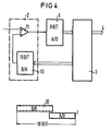
- digitization with a resolution of 18 bits is to be carried out using an 8 bit A / D converter and a measuring section selector, which consists of an 11 bit D / A converter 10 and a differential amplifier 11.
- the most significant bit of the D / A converter determines the selection of the measuring section by changing the value of the D / A converter by one step each, which corresponds to half the measuring range of the A / D converter.
- the A / D converter 1 and the D / A converter 10 are shown again as two columns. Together, the two converters cover 18 bits, which corresponds to the required resolution over the entire dynamic range.
- the least significant bit of the D / A converter 10 because of the much higher reference voltage on this converter, supplies an analog value which shifts the level converting signals by an amount in the differential amplifier 11 which corresponds exactly to the desired quarter of the measurement area of the A / D converter.
- the most significant bit of the A / D converter 1 determines via logic level 3 when and in which direction the value of the D / A converter and thus the measuring section is to be changed.
- FIG. 5 shows in a flow diagram the control levels that the logic level according to. Fig. 4 performs.
- the information (S n ) is read in from the A / D converter, as indicated in block 12. If the value S n lies outside the limit range of the A / D converter, a new difference between this value S n and the previous value S n-1 is formed directly from this value, as indicated in block 13. Thereafter, a reorganization is performed such that the last n a g e g moder value S, the new value S n-1. If a value S n comes again in the next cycle, the difference is formed again and so on. As indicated by block 14, these differences are added, for example, in a buffer stage. The respective signal of this buffer stage, which corresponds to the sum of all differences and thus the AC voltage component of the signal to be converted, is transmitted via a further stage 15. The reading in of a new value from the A / D converter is then triggered via line 16.
- the read-in value S n is greater than 3/4 of the measuring section or less than 1/4 of the same, ie if the value to be converted is within the limit range of the D / A converter, direct access to the difference generator is blocked. In this case, the value of the D / A converter is either reduced or increased via blocks 17 and 18. Since no new difference is formed, the last difference present is transferred to the buffer stage and thus added to the present value. Applying the same difference twice thus corresponds to a linear extrapolation to a new signal value.
Landscapes
- Engineering & Computer Science (AREA)
- Theoretical Computer Science (AREA)
- Analogue/Digital Conversion (AREA)
Applications Claiming Priority (2)
| Application Number | Priority Date | Filing Date | Title |
|---|---|---|---|
| DE3433898 | 1984-09-14 | ||
| DE3433898 | 1984-09-14 |
Publications (3)
| Publication Number | Publication Date |
|---|---|
| EP0177803A2 true EP0177803A2 (fr) | 1986-04-16 |
| EP0177803A3 EP0177803A3 (en) | 1988-08-31 |
| EP0177803B1 EP0177803B1 (fr) | 1991-05-29 |
Family
ID=6245467
Family Applications (1)
| Application Number | Title | Priority Date | Filing Date |
|---|---|---|---|
| EP85111624A Expired - Lifetime EP0177803B1 (fr) | 1984-09-14 | 1985-09-13 | Méthode et dispositif de numérisation d'un signal à haute résolution |
Country Status (4)
| Country | Link |
|---|---|
| US (1) | US4788528A (fr) |
| EP (1) | EP0177803B1 (fr) |
| JP (1) | JPS6178227A (fr) |
| DE (1) | DE3582992D1 (fr) |
Cited By (1)
| Publication number | Priority date | Publication date | Assignee | Title |
|---|---|---|---|---|
| WO1992002071A3 (fr) * | 1990-07-16 | 1992-03-19 | Eastman Kodak Co | Convertisseur analogique-numerique de type adaptatif a double gamme dynamique |
Families Citing this family (7)
| Publication number | Priority date | Publication date | Assignee | Title |
|---|---|---|---|---|
| JPS6319005A (ja) * | 1986-07-11 | 1988-01-26 | Omron Tateisi Electronics Co | 制御装置 |
| JP2501228B2 (ja) * | 1988-06-24 | 1996-05-29 | ファナック株式会社 | エンコ―ダの内挿回路 |
| TW267228B (en) * | 1994-06-02 | 1996-01-01 | Matsushita Electric Industrial Co Ltd | Data sample series access apparatus |
| JP3149837B2 (ja) * | 1997-12-08 | 2001-03-26 | 松下電器産業株式会社 | 回路形成基板の製造方法とその製造装置および回路形成基板用材料 |
| US6522489B1 (en) * | 1999-12-21 | 2003-02-18 | Texas Instruments Incorporated | Efficient analog-to-digital converter for digital systems |
| DE50114839D1 (de) * | 2000-08-02 | 2009-05-28 | Continental Teves Ag & Co Ohg | Aktiver magnetfeldsensor, dessen verwendung, verfahren und vorrichtung |
| EP2049874B1 (fr) * | 2006-08-01 | 2010-11-17 | Continental Teves AG & Co. oHG | Agencement de capteur pour une detection precise de mouvements relatifs entre un encodeur et un capteur |
Family Cites Families (8)
| Publication number | Priority date | Publication date | Assignee | Title |
|---|---|---|---|---|
| FR1481960A (fr) * | 1966-01-10 | 1967-05-26 | Societe D'etudes, Recherches Et Constructions Electroniques | Procédé et dispositif de codage numérique |
| US3516085A (en) * | 1969-05-15 | 1970-06-02 | Globe Union Inc | Analog to digital conversion system |
| US3913016A (en) * | 1974-04-18 | 1975-10-14 | Bell Telephone Labor Inc | Circuit for curtailing effects of bit errors in pulse coded transmission |
| US4204198A (en) * | 1977-12-20 | 1980-05-20 | The United States Of America As Represented By The Secretary Of The Army | Radar analog to digital converter |
| US4251802A (en) * | 1977-12-28 | 1981-02-17 | Horna Otakar A | Analog to digital converter |
| US4393369A (en) * | 1981-03-16 | 1983-07-12 | The United States Of America As Represented By The Secretary Of The Navy | Floating-point A/D and D/A converter |
| JPS5821921A (ja) * | 1981-07-31 | 1983-02-09 | Shimadzu Corp | A−d変換器 |
| US4540974A (en) * | 1981-10-30 | 1985-09-10 | Rca Corporation | Adaptive analog-to-digital converter |
-
1985
- 1985-09-13 DE DE8585111624T patent/DE3582992D1/de not_active Expired - Lifetime
- 1985-09-13 EP EP85111624A patent/EP0177803B1/fr not_active Expired - Lifetime
- 1985-09-13 JP JP60203223A patent/JPS6178227A/ja active Pending
-
1987
- 1987-05-15 US US07/051,162 patent/US4788528A/en not_active Expired - Fee Related
Cited By (1)
| Publication number | Priority date | Publication date | Assignee | Title |
|---|---|---|---|---|
| WO1992002071A3 (fr) * | 1990-07-16 | 1992-03-19 | Eastman Kodak Co | Convertisseur analogique-numerique de type adaptatif a double gamme dynamique |
Also Published As
| Publication number | Publication date |
|---|---|
| DE3582992D1 (de) | 1991-07-04 |
| EP0177803B1 (fr) | 1991-05-29 |
| EP0177803A3 (en) | 1988-08-31 |
| JPS6178227A (ja) | 1986-04-21 |
| US4788528A (en) | 1988-11-29 |
Similar Documents
| Publication | Publication Date | Title |
|---|---|---|
| DE3640672C2 (fr) | ||
| DE4209629B4 (de) | Absolutkodierer | |
| DE69825204T2 (de) | Eigenkalibrierung eines Oszilloskops mittels eines Rechteck-Testsignals | |
| DE3105782C2 (de) | Analog-Digitalumsetzer | |
| DE3836812C2 (fr) | ||
| DE3024716C2 (de) | Digitales Längen- oder Winkelmeßsystem | |
| DE3404066C2 (fr) | ||
| DE3249233C2 (fr) | ||
| DE3046797A1 (de) | Elektrooptisches messsystem mit fehlerkorrektur | |
| DE2814265A1 (de) | Verfahren und vorrichtung zur automatischen korrektur der einstellung eines mikroskops | |
| DE3210571C2 (fr) | ||
| EP0085951A2 (fr) | Procédé et dispositif pour établissement des grandeurs à mesurer | |
| EP0221251A1 (fr) | Méthode pour compenser des erreurs d'un capteur à caractéristique non linéaire et dispositif pour sa mise en oeuvre | |
| CH372732A (de) | Steuereinrichtung für einen Servomechanismus | |
| DE2706928A1 (de) | Analog-digital-umwandlungsverfahren und -system | |
| EP0177803A2 (fr) | Méthode et dispositif de numérisation d'un signal à haute résolution | |
| DE3717272C2 (fr) | ||
| DE2637620C2 (de) | Verfahren zum Regeln einer von mehreren Stellgrößen abhängigen Größe | |
| DE3413855A1 (de) | Verfahren zum auswerten von messsignalen, die durch abtastung eines inkrementalmassstabes mit einer abtasteinheit erhalten werden und messeinrichtung zur durchfuehrung dieses verfahrens | |
| DE3900531C2 (fr) | ||
| DE3114888C2 (de) | System zur Korrektur von Deckungs- und Schattenfehlern in einem Fernsehbild | |
| DE68907023T2 (de) | Mikrocomputergesteuerte schaltung zur lokalisierung von isolationsfehlern. | |
| DE2648515A1 (de) | Anordnung zur digitalen regelung | |
| DE2329446A1 (de) | Einrichtung zum darstellen und zeichnen einer linie | |
| DE4306855C1 (de) | Digitalisiereinrichtung |
Legal Events
| Date | Code | Title | Description |
|---|---|---|---|
| PUAI | Public reference made under article 153(3) epc to a published international application that has entered the european phase |
Free format text: ORIGINAL CODE: 0009012 |
|
| AK | Designated contracting states |
Kind code of ref document: A2 Designated state(s): DE FR GB IT SE |
|
| PUAL | Search report despatched |
Free format text: ORIGINAL CODE: 0009013 |
|
| AK | Designated contracting states |
Kind code of ref document: A3 Designated state(s): DE FR GB IT SE |
|
| 17P | Request for examination filed |
Effective date: 19881108 |
|
| 17Q | First examination report despatched |
Effective date: 19890822 |
|
| GRAA | (expected) grant |
Free format text: ORIGINAL CODE: 0009210 |
|
| AK | Designated contracting states |
Kind code of ref document: B1 Designated state(s): DE FR GB IT SE |
|
| PG25 | Lapsed in a contracting state [announced via postgrant information from national office to epo] |
Ref country code: SE Effective date: 19910529 |
|
| REF | Corresponds to: |
Ref document number: 3582992 Country of ref document: DE Date of ref document: 19910704 |
|
| ET | Fr: translation filed | ||
| ITF | It: translation for a ep patent filed | ||
| PGFP | Annual fee paid to national office [announced via postgrant information from national office to epo] |
Ref country code: GB Payment date: 19910822 Year of fee payment: 7 |
|
| GBT | Gb: translation of ep patent filed (gb section 77(6)(a)/1977) | ||
| PGFP | Annual fee paid to national office [announced via postgrant information from national office to epo] |
Ref country code: FR Payment date: 19910917 Year of fee payment: 7 |
|
| PGFP | Annual fee paid to national office [announced via postgrant information from national office to epo] |
Ref country code: DE Payment date: 19911127 Year of fee payment: 7 |
|
| PLBE | No opposition filed within time limit |
Free format text: ORIGINAL CODE: 0009261 |
|
| STAA | Information on the status of an ep patent application or granted ep patent |
Free format text: STATUS: NO OPPOSITION FILED WITHIN TIME LIMIT |
|
| 26N | No opposition filed | ||
| PG25 | Lapsed in a contracting state [announced via postgrant information from national office to epo] |
Ref country code: GB Effective date: 19920913 |
|
| GBPC | Gb: european patent ceased through non-payment of renewal fee |
Effective date: 19920913 |
|
| PG25 | Lapsed in a contracting state [announced via postgrant information from national office to epo] |
Ref country code: FR Effective date: 19930528 |
|
| PG25 | Lapsed in a contracting state [announced via postgrant information from national office to epo] |
Ref country code: DE Effective date: 19930602 |
|
| REG | Reference to a national code |
Ref country code: FR Ref legal event code: ST |