EP0177873B1 - Walzenandruck- und -abhebeeinrichtung - Google Patents
Walzenandruck- und -abhebeeinrichtung Download PDFInfo
- Publication number
- EP0177873B1 EP0177873B1 EP85112388A EP85112388A EP0177873B1 EP 0177873 B1 EP0177873 B1 EP 0177873B1 EP 85112388 A EP85112388 A EP 85112388A EP 85112388 A EP85112388 A EP 85112388A EP 0177873 B1 EP0177873 B1 EP 0177873B1
- Authority
- EP
- European Patent Office
- Prior art keywords
- lifting device
- roll pressure
- recesses
- web
- ball bearings
- Prior art date
- Legal status (The legal status is an assumption and is not a legal conclusion. Google has not performed a legal analysis and makes no representation as to the accuracy of the status listed.)
- Expired
Links
Images

Classifications
-
- G—PHYSICS
- G03—PHOTOGRAPHY; CINEMATOGRAPHY; ANALOGOUS TECHNIQUES USING WAVES OTHER THAN OPTICAL WAVES; ELECTROGRAPHY; HOLOGRAPHY
- G03D—APPARATUS FOR PROCESSING EXPOSED PHOTOGRAPHIC MATERIALS; ACCESSORIES THEREFOR
- G03D15/00—Apparatus for treating processed material
- G03D15/02—Drying; Glazing
-
- G—PHYSICS
- G03—PHOTOGRAPHY; CINEMATOGRAPHY; ANALOGOUS TECHNIQUES USING WAVES OTHER THAN OPTICAL WAVES; ELECTROGRAPHY; HOLOGRAPHY
- G03F—PHOTOMECHANICAL PRODUCTION OF TEXTURED OR PATTERNED SURFACES, e.g. FOR PRINTING, FOR PROCESSING OF SEMICONDUCTOR DEVICES; MATERIALS THEREFOR; ORIGINALS THEREFOR; APPARATUS SPECIALLY ADAPTED THEREFOR
- G03F7/00—Photomechanical, e.g. photolithographic, production of textured or patterned surfaces, e.g. printing surfaces; Materials therefor, e.g. comprising photoresists; Apparatus specially adapted therefor
- G03F7/16—Coating processes; Apparatus therefor
Definitions
- the invention relates to a roller pressure and lifting device with paired horizontally arranged upper and lower rollers for the transport of plate-shaped materials and for squeezing off residual liquid adhering to the plate-shaped materials, with a ball bearing which can be raised and lowered with respect to the lower roller at each axis end of each upper roller .
- the upper and lower rollers of a pair of rollers project with their shaft journals on each side into a housing.
- the lower bearing is fixed, while the upper bearing is pivotable about a pin eccentric to the bearing axis.
- the bearing is connected to a joint on its side opposite the journal.
- the hinge is hinged to a lower end of a lever which is pivotable about a horizontal pin.
- This pin is arranged in a bracket attached to the upper wall of the housing.
- an operating handle protrudes, which is connected to the pivotable lever.
- This lever and the joint form a toggle lever arrangement which, in its extended position, presses the upper roller against the lower roller and lifts the upper roller from the lower roller by turning the operating handle.
- a relief spring ensures that the upper roller is held in its raised position.
- the upper rollers must be lifted before longer downtimes, e.g. B. must be done overnight or over a weekend to avoid sticking of the upper rollers to the lower rollers, a variety of operating handles are operated, since each end of each upper roller is assigned a separate operating handle. This operation is cumbersome and time-consuming, so that there is a great risk of occasionally refraining from operating it.
- the rollers of the roller pairs remain pressed together for long periods of inactivity, the previously mentioned sticking and, in addition, deformations of their surfaces can occur, which ensure safe and gentle transport of plate-shaped materials, in particular printing plates, as well as perfect liquid squeezing, especially in horizontal processing plants for can endanger such plate-shaped materials.
- a device is known from EP-A-0 004 337, in which a pivotable fork head with an upper and a lower arm is provided for attacking the bearings of the upper rollers, the pivot axis of which is parallel to Printing plate transport direction is directed.
- the bearings can be actuated via a toggle lever arrangement, the upper arm of the pivotable fork head pressing the bearing from above when the bearing is lowered and the lower arm of the fork head supporting the bearing in the raised state.
- a first end of each toggle lever arrangement is connected to the fork head and a second end of each toggle lever arrangement is connected to a rotatable control shaft common to all toggle lever arrangements, which is mounted parallel to the pressure plate transport direction.
- the prior art also includes a device for developing printing plates with rollers arranged in pairs, the ends of which are mounted in side plates. These side plates are divided and equipped by means of a pivot point assigned to the upper side plate and corresponding lifting elements in such a way that the entire upper part of the side plates or the processing zone, including all of the upper rollers, can be raised.
- This device is also relatively expensive, especially when the lifting should not require too much effort by the operator.
- this arrangement cannot be used for devices which have a number of treatment stations, each treatment station being designed as a structural unit which can be combined with further structural units in modular construction to form the entire device.
- the object of the invention is to develop and improve a device of the type described at the outset such that, with structurally very simple means, reliable lifting and lowering of all the upper rollers from and onto the lower rollers is achieved with very little effort.
- the ball bearings are guided vertically in clasp-shaped guides, which are fixedly attached to the inner sides of side shields, that two sliding parts guided in slide bearings made of an upright U-profile with lower and upper web and a wall that adjacent to the respective side plate and has cutouts through which the guides protrude into the interior of the device by a predetermined distance back and forth, that the lower and upper web of the sliding parts contains recesses with a chamfered edge per recess and that the lower recesses are offset by the specified distance from the upper recesses.
- the roller pressing and lifting device is perpendicular to its longitudinal axis
- the roller axes run symmetrically, that is, on each side of the device, a sliding part is arranged, which is equipped with a rack, which is arranged above the upper web on an extension piece at one end of the sliding part and further a gear segment around an im Side shield of the device pivoted axis and is in engagement with the rack.
- a pivot lever is connected to the axis of the gear segment and the pivoting movement of the pivot lever is converted into a translational movement of the sliding part by the meshing of the gear segment and the rack.
- the lower and the upper web of the sliding part are each guided in a number of plastic plain bearings, which are attached to the inside of the associated side plate.
- the sliding part is pushed back and forth in the transport direction of the plate-shaped materials by means of the rotatably mounted gear segment, which is in engagement with the rack.
- the bevelled edges of the lower cutouts are directed against the transport direction of the plate-shaped materials and the bevelled edges of the upper cutouts run in the transport direction.
- the bevels of the edges are inclined planes for the ball bearings when moving the sliding parts, whereby in the pressing position the oblique edges of the recesses of the upper web press the ball bearings through the lower recesses and press the upper rollers onto the lower rollers and in the lifting position the the bevelled edges of the recesses of the lower web, raise the ball bearings that protrude freely through the upper recesses and lift the upper ones off the lower rollers.
- the sliding parts are stamped and bent parts made of sheet metal in a cost-effective manner.
- the predetermined distance between the center lines of a lower recess and an associated upper recess is equal to the distance or the displacement path of a sliding part.
- the recesses of equal size have a longitudinal dimension larger than the outside diameter of the ball bearings and the height of the wall of the sliding part is smaller than the outside diameter of the ball bearings.
- the ball bearings are expediently seated on the axis ends of the upper rollers and limit them laterally.
- a molded part is detachably attached to the upper web, adjacent to each recess, and is located between the underside of the upper web and the top of each Molding a number of intermediate layers with predetermined thicknesses.
- sliding parts which are produced from sheet metal by stamping and bending, achieves the advantages of a structurally simple construction, low manufacturing costs and low weight.
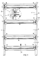
- FIG. 1 In the schematic plan view of the device 1 in FIG. 1, three processing stations I, II and 111 arranged in modules one behind the other can be seen, which, for example in transport direction A, are a development station, a washing station and a station for applying a protective layer to the developed and watered materials, especially printing plates, can act.
- the actual processing elements such as spray tubes, doctor blades and brush rollers are omitted in FIG. 1 for reasons of better clarity, but not the pairs of rollers necessary for transporting the printing plates through the device 1, which also ensure that residual liquid is squeezed off the printing plates.
- these roller pairs only the upper rollers 15 can be seen in plan view.
- the rollers 15 are mounted on their left and right sides, each with a ball bearing 6 in a sliding part 17, which can be pushed back and forth relative to side plates 20 of the device 1 in the transport direction A, as will be described in more detail later.
- the individual sliding part 17 consists of an upright U-profile with an upper and a lower web, which protrude from a wall 21 of the sliding part 17 and point into the interior of the device 1.
- the upper web 4 can be seen in the plan view, which in the region of the ball bearings 6, which are seated on the axis ends of the rollers 15, each has an upper recess 10.
- Each ball bearing 6 is further guided vertically to the plane of the drawing in a clip-shaped guide 7.
- the clasp-shaped guides 7 are fastened to the inner sides of the side plates 20 of the device 1.
- the enlarged detail in Fig. 1 shows in Be rich the recess 10 a broken upper web 4 and the wall 21 of the sliding part 17.
- the device 1 is constructed symmetrically, that is, it has both a sliding part 17 to the left and right side, which are largely identical.
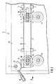
- Fig. 2 shows a schematic representation of the pressure position of the roller pairs, in which the upper rollers 15 are pressed against their associated lower rollers 14.
- the lower and the upper web 3 and 4 are each guided in a number of plain bearings 2, which are preferably plastic bearings.
- the plain bearings 2, 2, ... are attached to the inside of the associated side plate 20.
- the wall 21 of the sliding part 17 has cutouts 8, 8, ..., through which the clasp-shaped guides 7, 7, ... protrude into the interior of the device 1.
- the cutouts 8, 8, ... have the shape of an elongated rectangle, the long side of which is at least equal to the sum of the outside diameter of a ball bearing 6, the material thickness of the two side parts of the clasp-shaped guide which point inwards through the cutouts 8. 8 ...
- the displacement path of a sliding part 17 is a predetermined distance X, which corresponds to the distance between the center lines of a lower recess 9 in the lower web 3 and an associated upper recess 10 in the upper web 4 of the sliding part 17.
- the same size upper and lower recesses 9, 9, ... and 10, 10, ... have a longitudinal dimension larger than the outer diameter of the ball bearings 6, 6, ...
- the height H of the wall 21 of the sliding part 17 is smaller than that Outer diameter of the ball bearings 6, 6, ..., which sit on the axle ends 18, 18, ... of the upper rollers 15, 15, ... and limit them laterally.
- the sliding parts 17, 17 are punched and bent from sheet metal, the cutouts 8, 8, ... in the wall 21 and the lower and upper recesses 9, 9, ..., 10, 10 .... in one operation. be made in the lower and upper web 3 and 4. Then the sliding part 17 is then bent to the U-profile with the wall 21 and the two webs 3 and 4.
- the lower and upper recesses 9 and 10 have a beveled edge 5a and 5b, the beveled edges 5a, 5a, ... of the lower recesses 9, 9, ... are directed against the transport direction A of the printing plates and the Point bevelled edges 5b, 5b, ... of the upper cutouts 10, 10, ... in the direction of transport A.
- Each sliding part 17 is equipped with a toothed rack 11 which is arranged above the upper web 4 at one end of the sliding part 17 and runs parallel to the transport direction A.
- a gear segment 12 is in engagement with the rack 11 and is pivotable about an axis 13 mounted in the side plate 20.
- a pivot lever 16 is used, which is connected to the axis 13 of the gear segment 12. The pivoting movement of the pivoting lever 16 is converted into a translational movement of the sliding part 17 by the meshing of the gear segment and the rack.
- the pivot lever 16 is in its lower position, that is the pressing position of the roller pairs, in which the oblique edges 5b. 5b, ... of the recesses 10, 10 ....
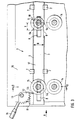
- FIG. 3 shows a schematic view of the lifting position of the roller pairs or of the sliding part 17.
- the same reference numerals are used for matching components in FIGS. 2 and 3 and the description of the components already explained with reference to FIG. 2 is not repeated.
- the pivot lever 16 is in the lifting position in its upper position, in which the gear segment 12 is approximately in engagement with the right end of the rack 11.
- the sliding part 17 is adjusted to the left by the displacement path X against the transport direction A.
- the ball bearings 6, 6, ... roll up on the slopes of the lower edges 5a, 5a, ... in the recesses 9, 9, ... of the lower web 3 and are thereby lifted in the clasp-shaped guides 7 and thus the upper rollers 15 are lifted off the lower rollers 14.
- the ball bearings 6, 6, ... of the upper rollers 15, 15, ... can thus be raised by a single pivoting movement of the pivoting levers 16, 16 of the sliding parts 17, 17, so that the operation for lifting and lowering the upper rollers is extremely simplified.
- the sliding parts 17, 17 prevent one of the ball bearings on one of the sides of the upper rollers from being accidentally lifted.
- the upper rollers 15, 15, ... can easily be removed from the device 1, cleaned and then reinserted.
- the lower rollers 14, 14, ... which are fixed in position in the side plates 20. 20, are easily accessible, so that maintenance and cleaning work can be carried out without great difficulty can be.
- the upper and lower rollers are pressurized accordingly pressed together to transport the printing plates and squeeze off the residual liquid on the printing plates.
- the upper rollers are brought into the raised position, so that deformation of the rollers and sticking of the rollers, which can lead to damage to the rubber coating, due to the residual liquids adhering to the rollers, for example Preservatives should be avoided.
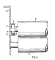
- FIG. 4 shows a partial view in section along the lines B-B in FIG. 3.
- the upper roller 15 is lifted off the lower roller 14.
- the ball bearing 6 is seated on the axis end 18 of the upper roller 15 and its upper contour edge projects into the upper recess 10 of the sliding part 17, while the lower contour edge of the ball bearing 6 does not protrude into the lower recess 9.
- the clasp-shaped guide 7 for the ball bearing 6 encloses the outer diameter of the ball bearing 6 at approximately the height of the center line of the upper roller 15 and is guided through the recess 8 in the wall 21 of the sliding part 17 and fastened to the inside of the side plate 20.
- Fig. 4 is also indicated that the lower roller 14 is mounted in a fixed position in the side plate 20. 4 shows only a left section or section of the device 1, which is followed by a right section constructed in the same way.
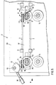
- the upper rollers depending on the position, by the axial displacement of the two sliding parts guided in slide bearings with an upstanding U-profile, formed from the lower and upper web which contain the recesses with bevelled edges pressed or lifted the lower rollers.
- the lower recess 9 has a beveled edge 5a, the beveled edges 5a, 5a, ... of the lower recesses 9, 9, ... being directed against the transport direction A of the printing plates, while the bevels 5c, 5c ... the molded parts 19 point in the direction of transport A.
- the molded parts 19 with their bevels 5c and their undersides 32 which act as contact surfaces, press the ball bearings 6 more or less strongly during axial displacement in the direction of transport A of the sliding parts 17, 17 and thereby the contact pressure of the upper rollers 15 determine on the pressure plate.
- the total number of intermediate layers 22 is generally kept somewhat larger than is necessary for the maximum necessary contact pressure, so that the sliding parts can only be moved into the contact position with the maximum contact pressure after the number of intermediate layers 22 has been reduced. This ensures that too much pressure due to too many intermediate layers, with the resulting defects on the developing device, is avoided.
- the intermediate layers 22 can have different thicknesses of 0.05 to 1.0 mm, uniform thicknesses of the intermediate layers 22 of 0.1 mm are preferred.
- Each intermediate layer is expediently embossed its thickness or strength numerically and dimensionally, so that without a measuring device and special tools in a simple manner by choosing the number of intermediate layers and thus the total thickness of the intermediate layers 22, which are between the molded parts 19 and the upper one Web 4 are used, the desired contact pressure can be set. The setting of the contact pressure will be described in more detail.
- Suitable material for the intermediate layers 22 is e.g. B. stainless steel.
- the intermediate layers and each molded part can also be arranged in the region of the lower rolls, in the case of fixed upper rolls.
- the lower rollers are then pressed against the upper rollers in a defined manner.
- FIG. 6a shows an enlarged sectional partial view of the molded part 19, the supply 23 of intermediate layers 22 and the intermediate layers 22 present between the molded part 19 and the underside of the web 4.
- the molded part 19 there are two bores 28, 29 with internal threads as in FIG. 6b can be seen. Two screws 24, 25 with edge heads are screwed into this internal thread, which penetrate holes 26, 27 of the intermediate rails 22 and holes 30, 31 of the upper web 4.
- the molded part 19 is held by the screws 24, 25 on the web 4 of the U-profile of the sliding part.
- There is a depression in the underside 32 or contact surface of the molded part 19 33 is present, in which the ball bearing 6 of the upper roller of the associated roller pair 14, 15 (see FIGS.
- FIGS. 6b and 6c which show top views of the molded part 19 and an intermediate layer 22, the bores 28, 29 with the internal threads, the recess 33 and the closed hole 26 and the hole 27 open towards the narrow side of the intermediate layer 22 are shown.
- the two screws 24, 25 In the screwed-in state, the two screws 24, 25 also hold the intermediate layers 22 of the supply 23 in place.
- the intermediate layers 22 have the laterally open hole 27 for one screw 25 and the closed hole 26 for the other screw 24.
- One screw 25 is captively secured when setting the contact pressure, for example by a circlip.
- the other screw 24 is unscrewed from the molded part 19 to change the contact pressure via the selected number of intermediate layers 22.
- the intermediate layers 22 on each end face of the upper roller 15 to be adjusted are removed in the pressing position of the sliding parts. Thereafter, without the need for a measuring device for determining the contact pressure, as many intermediate layers 22 are used near the two end faces of the rolls between the respective molded part 19 and the upper web 4 as is possible without any significant application of pressure.
- the sliding parts are then brought into the relaxed position and intermediate layers 22 are added from the supply 23 to the intermediate layers 22 between the respective molded part 19 and the upper web 4 in order to achieve the required roller contact pressure.
- the screw 24 is screwed in and tightened together with the secured screw 25 in order to immovably connect all parts such as the intermediate layers and the molded part to the web 4.
- the necessary roller pressure of the individual roller pairs can be stamped as a basic dimension on the webs of the sliding parts.
- the individual steps of setting the contact pressure take place on both sides of a pair of rollers in the same way, i. H. both sliding parts must always be pressed or relaxed at the same time.
Landscapes
- Physics & Mathematics (AREA)
- General Physics & Mathematics (AREA)
- Rolls And Other Rotary Bodies (AREA)
- Transmission Devices (AREA)
- Delivering By Means Of Belts And Rollers (AREA)
- Rollers For Roller Conveyors For Transfer (AREA)
Priority Applications (1)
| Application Number | Priority Date | Filing Date | Title |
|---|---|---|---|
| AT85112388T ATE40014T1 (de) | 1984-10-09 | 1985-10-01 | Walzenandruck- und -abhebeeinrichtung. |
Applications Claiming Priority (4)
| Application Number | Priority Date | Filing Date | Title |
|---|---|---|---|
| DE3436980 | 1984-10-09 | ||
| DE19843436980 DE3436980A1 (de) | 1984-10-09 | 1984-10-09 | Walzenandruck- und -abhebeeinrichtung |
| DE19853530680 DE3530680A1 (de) | 1985-08-28 | 1985-08-28 | Walzendruck- und -abhebeeinrichtung |
| DE3530680 | 1985-08-28 |
Publications (2)
| Publication Number | Publication Date |
|---|---|
| EP0177873A1 EP0177873A1 (de) | 1986-04-16 |
| EP0177873B1 true EP0177873B1 (de) | 1989-01-11 |
Family
ID=25825494
Family Applications (1)
| Application Number | Title | Priority Date | Filing Date |
|---|---|---|---|
| EP85112388A Expired EP0177873B1 (de) | 1984-10-09 | 1985-10-01 | Walzenandruck- und -abhebeeinrichtung |
Country Status (6)
| Country | Link |
|---|---|
| US (1) | US4632382A (da) |
| EP (1) | EP0177873B1 (da) |
| CA (1) | CA1244790A (da) |
| DE (1) | DE3567547D1 (da) |
| DK (1) | DK161485C (da) |
| ES (1) | ES8703383A1 (da) |
Families Citing this family (4)
| Publication number | Priority date | Publication date | Assignee | Title |
|---|---|---|---|---|
| US5011129A (en) * | 1989-11-14 | 1991-04-30 | Pitney Bowes Inc. | Jam clearance apparatus for sheetfeeding device |
| DE69226189T2 (de) * | 1992-10-28 | 1999-02-18 | Agfa-Gevaert N.V., Mortsel | Photographisches Entwicklungsgerät |
| DE69708648T2 (de) * | 1996-07-31 | 2002-08-01 | Agfa-Gevaert N.V., Mortsel | Gerät zum entwickeln von blattmaterial |
| CN104649045B (zh) * | 2014-12-25 | 2016-12-07 | 杭州科雷机电工业有限公司 | 一种四向输送模块及其联网式印版自动分流处理方法 |
Family Cites Families (8)
| Publication number | Priority date | Publication date | Assignee | Title |
|---|---|---|---|---|
| GB343963A (en) * | 1929-01-31 | 1931-02-26 | Andre Leon Victor Clement Debr | Machine for developing photographic and cinematographic films |
| US1925972A (en) * | 1932-07-18 | 1933-09-05 | Downingtown Mfg Co | Primary press section for paper machines |
| US2965374A (en) * | 1958-04-29 | 1960-12-20 | Thrissell Engineering Company | Letter sorting machines |
| DE1276443B (de) * | 1963-11-27 | 1968-08-29 | Arnold & Richter Kg | Zahnkranzlose Filmentwicklungsmaschine mit Trockenschrank |
| DE2326122B2 (de) * | 1972-05-26 | 1978-04-13 | Joergen Virum Bech (Daenemark) | Maschine zum Entwickeln von Offset-Druckplatten |
| JPS5927898B2 (ja) * | 1976-09-11 | 1984-07-09 | ノ−リツ鋼機株式会社 | 写真処理機 |
| DE2812688A1 (de) * | 1978-03-23 | 1979-10-04 | Hoechst Ag | Einrichtung zum entwickeln von druckplatten mit paarweise angeordneten oberen und unteren walzen |
| GB2108706B (en) * | 1981-11-06 | 1985-11-20 | Wainco Prod Ltd | Film processor |
-
1985
- 1985-10-01 DE DE8585112388T patent/DE3567547D1/de not_active Expired
- 1985-10-01 EP EP85112388A patent/EP0177873B1/de not_active Expired
- 1985-10-04 US US06/784,538 patent/US4632382A/en not_active Expired - Fee Related
- 1985-10-08 ES ES547695A patent/ES8703383A1/es not_active Expired
- 1985-10-08 DK DK457785A patent/DK161485C/da active
- 1985-10-08 CA CA000492474A patent/CA1244790A/en not_active Expired
Also Published As
| Publication number | Publication date |
|---|---|
| DK457785A (da) | 1986-04-10 |
| DK161485B (da) | 1991-07-08 |
| DK457785D0 (da) | 1985-10-08 |
| CA1244790A (en) | 1988-11-15 |
| DE3567547D1 (en) | 1989-02-16 |
| DK161485C (da) | 1991-12-16 |
| ES547695A0 (es) | 1987-02-16 |
| EP0177873A1 (de) | 1986-04-16 |
| US4632382A (en) | 1986-12-30 |
| ES8703383A1 (es) | 1987-02-16 |
Similar Documents
| Publication | Publication Date | Title |
|---|---|---|
| DE3534428C2 (da) | ||
| DE1510215B1 (de) | Presswalzenteil mit gekreuzten Walzen | |
| CH688205A5 (de) | Vorrichtung zur Behandlung von Flachmaterial. | |
| DE3025799C2 (de) | Preßwalze, deren Durchbiegung einstellbar ist | |
| DE2239966A1 (de) | Verfahren und vorrichtung zum ausrichten eines stranggusskoerpers | |
| DE1527601A1 (de) | Walzwerk | |
| DE69205554T2 (de) | Rotationsstanzvorrichtung. | |
| DE3140548C1 (de) | Doppelbandpresse | |
| DE1778337B1 (de) | Endloser foerderer zur verwendung bei einer automatischen lackieranlage fuer plattenfoermige werkstuecke | |
| EP0177873B1 (de) | Walzenandruck- und -abhebeeinrichtung | |
| DE3619648A1 (de) | Bindekamm-schliessvorrichtung | |
| EP0512267A2 (de) | Kaschiermaschine | |
| DE2835514B1 (de) | Vorrichtung zum axialen Verschieben von konischen Zwischenwalzen in einem Mehrrollen-Walzgeruest | |
| DE69705221T4 (de) | Metallplattenbiegevorrichtung mit offsetdruckrollen | |
| AT392661B (de) | Presswalze, deren durchbiegung einstellbar ist | |
| EP0004337B1 (de) | Einrichtung zum Entwickeln von Druckplatten mit paarweise horizontal angeordneten oberen und unteren Walzen | |
| DE69924466T2 (de) | Abstreifvorrichtung für flüssigkeiten | |
| DE2729938C3 (de) | Doppelbandpresse zum Herstellen von Preßplatten | |
| DE2545624C3 (de) | Presse zur Ausübung einer Flächenpressung | |
| DE3407485A1 (de) | Walzvorrichtung | |
| DE69409556T2 (de) | Rotierende Schneidvorrichtung | |
| DE2853285A1 (de) | Vorrichtung zum aufbringen einer flaechenpressung auf fortschreitende werkstuecke mit mindestens einem umlaufenden pressband | |
| DE3436980A1 (de) | Walzenandruck- und -abhebeeinrichtung | |
| DE3530680A1 (de) | Walzendruck- und -abhebeeinrichtung | |
| DE2939451C2 (de) | Maschine zum Schneiden von Wellpappe |
Legal Events
| Date | Code | Title | Description |
|---|---|---|---|
| PUAI | Public reference made under article 153(3) epc to a published international application that has entered the european phase |
Free format text: ORIGINAL CODE: 0009012 |
|
| AK | Designated contracting states |
Kind code of ref document: A1 Designated state(s): AT BE DE FR GB IT NL SE |
|
| 17P | Request for examination filed |
Effective date: 19860926 |
|
| 17Q | First examination report despatched |
Effective date: 19880318 |
|
| GRAA | (expected) grant |
Free format text: ORIGINAL CODE: 0009210 |
|
| AK | Designated contracting states |
Kind code of ref document: B1 Designated state(s): AT BE DE FR GB IT NL SE |
|
| REF | Corresponds to: |
Ref document number: 40014 Country of ref document: AT Date of ref document: 19890115 Kind code of ref document: T |
|
| REF | Corresponds to: |
Ref document number: 3567547 Country of ref document: DE Date of ref document: 19890216 |
|
| ET | Fr: translation filed | ||
| ITF | It: translation for a ep patent filed | ||
| GBT | Gb: translation of ep patent filed (gb section 77(6)(a)/1977) | ||
| PLBE | No opposition filed within time limit |
Free format text: ORIGINAL CODE: 0009261 |
|
| STAA | Information on the status of an ep patent application or granted ep patent |
Free format text: STATUS: NO OPPOSITION FILED WITHIN TIME LIMIT |
|
| 26N | No opposition filed | ||
| PGFP | Annual fee paid to national office [announced via postgrant information from national office to epo] |
Ref country code: SE Payment date: 19920921 Year of fee payment: 8 |
|
| PGFP | Annual fee paid to national office [announced via postgrant information from national office to epo] |
Ref country code: AT Payment date: 19920928 Year of fee payment: 8 |
|
| PGFP | Annual fee paid to national office [announced via postgrant information from national office to epo] |
Ref country code: BE Payment date: 19921009 Year of fee payment: 8 |
|
| ITTA | It: last paid annual fee | ||
| PG25 | Lapsed in a contracting state [announced via postgrant information from national office to epo] |
Ref country code: AT Effective date: 19931001 |
|
| PG25 | Lapsed in a contracting state [announced via postgrant information from national office to epo] |
Ref country code: SE Effective date: 19931002 |
|
| PG25 | Lapsed in a contracting state [announced via postgrant information from national office to epo] |
Ref country code: BE Effective date: 19931031 |
|
| PGFP | Annual fee paid to national office [announced via postgrant information from national office to epo] |
Ref country code: DE Payment date: 19931221 Year of fee payment: 9 |
|
| BERE | Be: lapsed |
Owner name: HOECHST A.G. Effective date: 19931031 |
|
| PGFP | Annual fee paid to national office [announced via postgrant information from national office to epo] |
Ref country code: FR Payment date: 19940913 Year of fee payment: 10 |
|
| PGFP | Annual fee paid to national office [announced via postgrant information from national office to epo] |
Ref country code: GB Payment date: 19940923 Year of fee payment: 10 |
|
| PGFP | Annual fee paid to national office [announced via postgrant information from national office to epo] |
Ref country code: NL Payment date: 19941031 Year of fee payment: 10 |
|
| EUG | Se: european patent has lapsed |
Ref document number: 85112388.5 Effective date: 19940510 |
|
| PG25 | Lapsed in a contracting state [announced via postgrant information from national office to epo] |
Ref country code: DE Effective date: 19950701 |
|
| PG25 | Lapsed in a contracting state [announced via postgrant information from national office to epo] |
Ref country code: GB Effective date: 19951001 |
|
| PG25 | Lapsed in a contracting state [announced via postgrant information from national office to epo] |
Ref country code: NL Effective date: 19960501 |
|
| GBPC | Gb: european patent ceased through non-payment of renewal fee |
Effective date: 19951001 |
|
| PG25 | Lapsed in a contracting state [announced via postgrant information from national office to epo] |
Ref country code: FR Effective date: 19960628 |
|
| NLV4 | Nl: lapsed or anulled due to non-payment of the annual fee |
Effective date: 19960501 |
|
| REG | Reference to a national code |
Ref country code: FR Ref legal event code: ST |