EP0177951B1 - Appareil de commutation du type coffret - Google Patents
Appareil de commutation du type coffret Download PDFInfo
- Publication number
- EP0177951B1 EP0177951B1 EP85112801A EP85112801A EP0177951B1 EP 0177951 B1 EP0177951 B1 EP 0177951B1 EP 85112801 A EP85112801 A EP 85112801A EP 85112801 A EP85112801 A EP 85112801A EP 0177951 B1 EP0177951 B1 EP 0177951B1
- Authority
- EP
- European Patent Office
- Prior art keywords
- main
- tank
- auxiliary
- lever
- contact
- Prior art date
- Legal status (The legal status is an assumption and is not a legal conclusion. Google has not performed a legal analysis and makes no representation as to the accuracy of the status listed.)
- Expired
Links
Images

Classifications
-
- H—ELECTRICITY
- H01—ELECTRIC ELEMENTS
- H01H—ELECTRIC SWITCHES; RELAYS; SELECTORS; EMERGENCY PROTECTIVE DEVICES
- H01H33/00—High-tension or heavy-current switches with arc-extinguishing or arc-preventing means
- H01H33/02—Details
- H01H33/04—Means for extinguishing or preventing arc between current-carrying parts
- H01H33/12—Auxiliary contacts on to which the arc is transferred from the main contacts
-
- H—ELECTRICITY
- H02—GENERATION; CONVERSION OR DISTRIBUTION OF ELECTRIC POWER
- H02B—BOARDS, SUBSTATIONS OR SWITCHING ARRANGEMENTS FOR THE SUPPLY OR DISTRIBUTION OF ELECTRIC POWER
- H02B13/00—Arrangement of switchgear in which switches are enclosed in, or structurally associated with, a casing, e.g. cubicle
- H02B13/02—Arrangement of switchgear in which switches are enclosed in, or structurally associated with, a casing, e.g. cubicle with metal casing
- H02B13/035—Gas-insulated switchgear
-
- H—ELECTRICITY
- H01—ELECTRIC ELEMENTS
- H01H—ELECTRIC SWITCHES; RELAYS; SELECTORS; EMERGENCY PROTECTIVE DEVICES
- H01H3/00—Mechanisms for operating contacts
- H01H3/32—Driving mechanisms, i.e. for transmitting driving force to the contacts
- H01H3/46—Driving mechanisms, i.e. for transmitting driving force to the contacts using rod or lever linkage, e.g. toggle
Definitions
- The. present invention relates to a tank-type switchgear in which movable contact elements of main and auxiliary contacts are moved by driving means through a link mechanism.
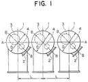
- a manhole 2 is often formed in the perimeter of a cylindrical tank 1 to make it possible to inspect a main contact 3 or an auxiliary contact 4 disposed in the tank 1.
- the size of the switchgear has been recently reduced.
- To reduce the diameter D of the tank and the distance L between the tanks it is necessary to dispose the manhole 2 along the line B-B, which slants by a predetermined angle with respect to line A-A along which the tanks are aligned. In such a case, for ease of inspection, it is preferable to dispose the main and auxiliary contacts 3 and 4 within the tank 1 along line B-B along which the manholes 2 are arranged.
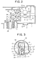
- the main contact 3 comprises a stationary contact element 5 and a movable contact element 6, and the auxiliary contact 4 comprises a stationary contact element 7 and a movable contact element 8.
- the stationary contact elements 5 and 7 of the main and auxiliary contacts are electrically connected to a conductor 9 which is electrically insulated from and supported by the tank 1 through an insulated support member 10.
- the movable contact elements 6 and 8 of the main and auxiliary contacts 3 and 4 respectively oppose the stationary contact elements 5 and 7 and are connected to a link device 13.
- the link device 13 is disposed within a link box 12 supported by and electrically insulated from the tank 1 through an insulated cylinder 11.
- the link device 13 comprises an L-shaped main lever 15 rotatably connected to a stationary shaft 14 supported by the box 12, and an L-shaped auxiliary lever 17 rotatably connected to a stationary shaft 16 supported by the box 12.
- One end of the main lever 15 is connected to one end of the movable contact element 6 through a link 18 and connecting pins 19 and 20 at both ends thereof.
- One end of the auxiliary lever 17 is connected to one end of the movable contact element 8 through a link 21 and connecting pins 22 and 23 at both ends thereof.
- the other ends of the main and auxiliary levers 15 and 17 are connected to an insulated driving rod 29 extending into the insulated cylinder 11 through links 24 and 25 and connecting pins 26, 27 and 28.
- the driving rod 29 is connected to an unillustrated driving apparatus and transmits driving force from the driving apparatus to the link device 13.
- the switchgear to reduce the size of the tank 1, it is preferable to dispose the main contact 3 and the auxiliary contact 4 such that, as shown in Fig. 3, the center of a circle 30 enclosing the main and auxiliary contacts 3 and 4 and contacting the outer surfaces thereof is located approximately at the axis of the cylindrical tank 1.
- the link box 12 extends downwards to support the stationary shaft 16 which is a fulcrum of the auxiliary lever 17. Accordingly, the distance 1 1 between the center of the circle 30 and the bottom end of the box 12 is large, increasing the size of the link box 12.
- the distance between the tank 1 and the box 12 must be longer than a predetermined length to ensure electrical insulation therebetween. Accordingly, the conventional switchgear has the disadvantages that the inner diameter of the tank is large, increasing the size of the tank.
- an object of the present invention is to provide a tank-type switchgear in which a link device for driving main and auxiliary contacts is compact, thereby reducing the size of the tank.
- a tank-type switchgear comprising a main contact disposed in a hollow tank and having movable and stationary contact elements, an auxiliary contact disposed in the tank and electrically connected parallel with the main contact and having movable and stationary contact elements, a main lever rotatably connected to the movable contact element of the main contact, an auxiliary lever rotatably connected at one end thereof to the movable contact element of the auxiliary contact, a connecting link for rotatably supporting the other end of the auxiliary lever, means for rotatably supporting the main lever and the connecting link with respect to the tank, and driving means for rotating the main lever, said auxiliary lever being rotatably connected to the main lever such that the auxiliary lever rotates in the direction opposite the rotational direction of the main lever.
- a manhole 52 is formed in the periphery of a cylindrical hollow tank 51 to make it possible to inspect a main contact 53 and an auxiliary contact 54 disposed in the tank 51.
- the main contact 53 comprises a stationary contact elment 55 and a movable contact element 56
- the auxiliary contact 54 comprises a stationary contact element 57 and a movable contact element 58.
- the stationary contact elements 55 and 57 of the main and auxiliary contacts are electrically connected to a conductor 59 electrically insulated from and supported by the tank 51 through an insulated support member 60.
- the movable contact elements 56 and 58 respectively oppose the stationary contact elements 55 and 57, and are connected to a link device 81.
- the link device 81 is disposed within a link box 62 supported by and electrically insulated from the tank 51 through an insulated cylinder 61.
- the link device 81 comprises an L-shaped main lever 82 rotatably supported by a stationary shaft 83 secured to the link box 62, and an auxiliary lever 85 rotatable connected by a pin 84 to the leg of the main lever 82 on the side near the contacts at the intermediate portion of the auxiliary lever 85.
- One end of the main lever 82 is connected to the movable contact element 56 through a link 68 and pins 69 and 70, and the other end of the main lever 82 is connected to a driving rod 79 through a link 74 and pins 76 and 78.
- the pin 84 is preferably secured to the main lever 82 midway between the stationary shaft 83 and the end of the main lever 82 connected to the link 68.
- One end of the auxiliary lever 85 is connected to the movable contact element 58 through a link 71 and pins 72 and 73.
- the other end of the auxiliary lever 85 is rotatably connected by a pin 86 to one end of a link 87 which is rotatably supported by a stationary shaft 88 secured to the box 62.
- the auxiliary lever 85 may be made of a straight bar and has one end located near the auxiliary contact 54 and the other end supported by the stationary shaft 88 through the link 87, as shown in Fig. 5, the stationary shaft 88 can be substantially disposed within the link box 62 in a corner opposite the corner in which the stationary shaft 83 is disposed with respect to the center of the box 62.
- the centre of a circle 80 enclosing the movable contact elements 56 and 58 and contacting the outer surfaces thereof is located at approximately the axis of the cylindrical tank 51. Therefore, the distance 1 2 between the bottom end of the box 62 and the central line C-C of the circle 80 is shorter than the distance 1 1 in the conventional switchgear, so that the link device 81 and thereby the link box 62 are compact and the size of the tank 51 is reduced.
Landscapes
- Engineering & Computer Science (AREA)
- Power Engineering (AREA)
- Gas-Insulated Switchgears (AREA)
- Driving Mechanisms And Operating Circuits Of Arc-Extinguishing High-Tension Switches (AREA)
Claims (6)
Applications Claiming Priority (2)
| Application Number | Priority Date | Filing Date | Title |
|---|---|---|---|
| JP59211474A JPS6191809A (ja) | 1984-10-11 | 1984-10-11 | タンク形開閉装置 |
| JP211474/84 | 1984-10-11 |
Publications (3)
| Publication Number | Publication Date |
|---|---|
| EP0177951A2 EP0177951A2 (fr) | 1986-04-16 |
| EP0177951A3 EP0177951A3 (en) | 1986-10-22 |
| EP0177951B1 true EP0177951B1 (fr) | 1989-07-05 |
Family
ID=16606542
Family Applications (1)
| Application Number | Title | Priority Date | Filing Date |
|---|---|---|---|
| EP85112801A Expired EP0177951B1 (fr) | 1984-10-11 | 1985-10-09 | Appareil de commutation du type coffret |
Country Status (5)
| Country | Link |
|---|---|
| US (1) | US4652708A (fr) |
| EP (1) | EP0177951B1 (fr) |
| JP (1) | JPS6191809A (fr) |
| CN (1) | CN85108383B (fr) |
| DE (1) | DE3571361D1 (fr) |
Families Citing this family (16)
| Publication number | Priority date | Publication date | Assignee | Title |
|---|---|---|---|---|
| US4814834A (en) * | 1984-04-03 | 1989-03-21 | Canon Kabushiki Kaisha | Electrophotographic apparatus |
| DE3506383A1 (de) * | 1985-02-23 | 1986-09-04 | Sachsenwerk, Licht- und Kraft-AG, 8000 München | Elektrische schaltanlagen und schaltverfahren dieser anlage |
| DE3513264A1 (de) * | 1985-03-12 | 1986-09-18 | BBC Aktiengesellschaft Brown, Boveri & Cie., Baden, Aargau | Druckgasschalter |
| JPS61290616A (ja) * | 1985-06-18 | 1986-12-20 | 三菱電機株式会社 | 碍子形ガス遮断器 |
| EP0483121B1 (fr) * | 1986-06-06 | 1994-09-07 | Mitsubishi Denki Kabushiki Kaisha | Appareillage interrupteur |
| JPH0619937B2 (ja) * | 1986-07-14 | 1994-03-16 | 三菱電機株式会社 | ガス遮断器用連結装置 |
| JPH0767213B2 (ja) * | 1986-09-29 | 1995-07-19 | 三菱電機株式会社 | ガス絶縁開閉装置 |
| JPH0623130Y2 (ja) * | 1986-10-07 | 1994-06-15 | 三菱電機株式会社 | ガス絶縁開閉装置 |
| JPS63121408A (ja) * | 1986-11-11 | 1988-05-25 | 三菱電機株式会社 | 三相一括形ガス絶縁開閉装置 |
| US5107081A (en) * | 1987-10-26 | 1992-04-21 | Mitsubishi Denki Kabushiki Kaisha | Operating mechanism for gas filled switchgear |
| JP2743740B2 (ja) * | 1992-11-05 | 1998-04-22 | 三菱電機株式会社 | ガス絶縁開閉器 |
| FR2770678B1 (fr) * | 1997-10-30 | 1999-12-31 | Gec Alsthom T & D Sa | Disjoncteur de generateur a commande mecanique unique |
| EP2568493B1 (fr) * | 2011-09-06 | 2015-12-16 | ABB Research Ltd. | Dispositif de commutation haute tension |
| EP2831898B1 (fr) * | 2012-03-30 | 2016-03-30 | ABB Technology Ltd. | Commutation de circuit électrique |
| WO2018027545A1 (fr) * | 2016-08-09 | 2018-02-15 | 尚艳燕 | Véhicule à équilibrage électrique et ensemble pédale associé |
| CN107706039B (zh) * | 2017-09-27 | 2019-10-29 | 中国西电电气股份有限公司 | 一种断路器及双拐臂传动装置 |
Family Cites Families (9)
| Publication number | Priority date | Publication date | Assignee | Title |
|---|---|---|---|---|
| US1820710A (en) * | 1926-04-23 | 1931-08-25 | Westinghouse Electric & Mfg Co | High speed oil circuit breaker |
| DE450141C (de) * | 1926-04-23 | 1927-10-01 | Siemens Schuckertwerke G M B H | Schnellschalter mit Hauptkontakten und Loeschkontakten im OElkessel |
| US3671696A (en) * | 1970-11-16 | 1972-06-20 | Allis Chalmers Mfg Co | Vacuum interrupter shunted with mechanical switch |
| US4009458A (en) * | 1975-04-15 | 1977-02-22 | Hitachi, Ltd. | Puffer type gas circuit breaker |
| JPS5463378A (en) * | 1977-10-31 | 1979-05-22 | Tokyo Shibaura Electric Co | Tank type buffer breaker |
| JPS5465375A (en) * | 1977-11-01 | 1979-05-25 | Tokyo Shibaura Electric Co | Tank type buffer breaker |
| FR2447090A1 (fr) * | 1979-01-16 | 1980-08-14 | Hitachi Ltd | Disposition et commande d'un disjoncteur haute tension blinde a gaz isolant |
| JPS5840715A (ja) * | 1981-09-04 | 1983-03-09 | 株式会社東芝 | しや断器 |
| JPS58206019A (ja) * | 1982-05-27 | 1983-12-01 | 株式会社東芝 | しや断器 |
-
1984
- 1984-10-11 JP JP59211474A patent/JPS6191809A/ja active Pending
-
1985
- 1985-10-03 CN CN85108383A patent/CN85108383B/zh not_active Expired
- 1985-10-09 DE DE8585112801T patent/DE3571361D1/de not_active Expired
- 1985-10-09 EP EP85112801A patent/EP0177951B1/fr not_active Expired
- 1985-10-09 US US06/785,716 patent/US4652708A/en not_active Expired - Lifetime
Also Published As
| Publication number | Publication date |
|---|---|
| JPS6191809A (ja) | 1986-05-09 |
| DE3571361D1 (en) | 1989-08-10 |
| EP0177951A3 (en) | 1986-10-22 |
| CN85108383A (zh) | 1986-07-16 |
| CN85108383B (zh) | 1988-03-09 |
| EP0177951A2 (fr) | 1986-04-16 |
| US4652708A (en) | 1987-03-24 |
Similar Documents
| Publication | Publication Date | Title |
|---|---|---|
| US4652708A (en) | Tank-type switchgear | |
| CA1216020A (fr) | Interrupteur de mise a la terre | |
| US4554420A (en) | Electrical switch | |
| US4510360A (en) | Circuit breaker with arc shield | |
| EP0463491B1 (fr) | Disjoncteur rempli de gaz | |
| JPS5935163B2 (ja) | 切換可能なタツプ間巻線を有する切換タツプ付変圧器用の極性開閉器を有する負荷時タツプ切換装置 | |
| JPH0928011A (ja) | ガス絶縁開閉装置の断路器および接地開閉器 | |
| US2889435A (en) | Telescoping blade switch | |
| JPH0361972B2 (fr) | ||
| JPH1153998A (ja) | ガス遮断器 | |
| JP2597541B2 (ja) | ガス遮断器 | |
| JPH0767214B2 (ja) | ガス絶縁開閉器 | |
| JPS6321872Y2 (fr) | ||
| JPH1064381A (ja) | 遮断器の操作機構 | |
| EP1156502A1 (fr) | Actionneur d'interrupteur a coupure en charge | |
| JP2000067713A (ja) | 開閉装置 | |
| JPH0360133B2 (fr) | ||
| US11875955B2 (en) | Vacuum circuit breaker | |
| JPS6211127Y2 (fr) | ||
| KR100308164B1 (ko) | 회로차단기 | |
| JP2563096B2 (ja) | 高電圧遮断器 | |
| US3299230A (en) | Electrical switch having a pivotable and rotatable blade and switch operating mechanism therefor | |
| US3717733A (en) | Centrifugal switch | |
| FI96805B (fi) | Kytkinlaitteen ohjausmekanismi | |
| JP2590655Y2 (ja) | 3相一括形開閉器 |
Legal Events
| Date | Code | Title | Description |
|---|---|---|---|
| PUAI | Public reference made under article 153(3) epc to a published international application that has entered the european phase |
Free format text: ORIGINAL CODE: 0009012 |
|
| AK | Designated contracting states |
Kind code of ref document: A2 Designated state(s): CH DE FR LI |
|
| PUAL | Search report despatched |
Free format text: ORIGINAL CODE: 0009013 |
|
| AK | Designated contracting states |
Kind code of ref document: A3 Designated state(s): CH DE FR LI |
|
| 17P | Request for examination filed |
Effective date: 19870326 |
|
| 17Q | First examination report despatched |
Effective date: 19880915 |
|
| GRAA | (expected) grant |
Free format text: ORIGINAL CODE: 0009210 |
|
| AK | Designated contracting states |
Kind code of ref document: B1 Designated state(s): CH DE FR LI |
|
| REF | Corresponds to: |
Ref document number: 3571361 Country of ref document: DE Date of ref document: 19890810 |
|
| ET | Fr: translation filed | ||
| PLBE | No opposition filed within time limit |
Free format text: ORIGINAL CODE: 0009261 |
|
| STAA | Information on the status of an ep patent application or granted ep patent |
Free format text: STATUS: NO OPPOSITION FILED WITHIN TIME LIMIT |
|
| 26N | No opposition filed | ||
| REG | Reference to a national code |
Ref country code: FR Ref legal event code: D6 |
|
| PGFP | Annual fee paid to national office [announced via postgrant information from national office to epo] |
Ref country code: FR Payment date: 19981009 Year of fee payment: 14 |
|
| PGFP | Annual fee paid to national office [announced via postgrant information from national office to epo] |
Ref country code: DE Payment date: 19981016 Year of fee payment: 14 |
|
| PGFP | Annual fee paid to national office [announced via postgrant information from national office to epo] |
Ref country code: CH Payment date: 19981022 Year of fee payment: 14 |
|
| PG25 | Lapsed in a contracting state [announced via postgrant information from national office to epo] |
Ref country code: LI Free format text: LAPSE BECAUSE OF NON-PAYMENT OF DUE FEES Effective date: 19991031 Ref country code: CH Free format text: LAPSE BECAUSE OF NON-PAYMENT OF DUE FEES Effective date: 19991031 |
|
| REG | Reference to a national code |
Ref country code: CH Ref legal event code: PL |
|
| PG25 | Lapsed in a contracting state [announced via postgrant information from national office to epo] |
Ref country code: FR Free format text: LAPSE BECAUSE OF NON-PAYMENT OF DUE FEES Effective date: 20000630 |
|
| PG25 | Lapsed in a contracting state [announced via postgrant information from national office to epo] |
Ref country code: DE Free format text: LAPSE BECAUSE OF NON-PAYMENT OF DUE FEES Effective date: 20000801 |
|
| REG | Reference to a national code |
Ref country code: FR Ref legal event code: ST |